
Subscribe to Our Youtube Channel
Related Manuals for Palmgren 9661610


Summary of Contents for Palmgren 9661610
- Page 1 Operating Instructions & Parts Manual 10 Ton Manual Hydraulic Press Standard and Tall Models 9661610/9661611 9643566.01...
- Page 2 DAMAGE! RETAIN INSTRUCTIONS FOR FUTURE REFERENCE. PLEASE REFER TO BACK COVER FOR INFORMATION REGARDING PALMGREN’S WARRANTY AND OTHER IMPORTANT INFORMATION. Model #: ___________________ Serial #: ___________________ Purch. Date: _______________ © 2019 Palmgren / a C.H. Hanson Brand All Rights Reserved...
-
Page 3: Getting Started
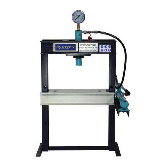
GETTING STARTED Package Contents: Pipe holder Save this manual Hydraulic pump assembly You will need this manual for the safety warnings and precau- Frame with cylinder tions, assembly instructions, operating and maintenance procedures, parts lists and diagrams. Keep your invoice with this Bag of replaement rubber manual. - Page 4 SAFETY RULES Preparing the work area for your job • Do not use this machine in dangerous environments. Do not Completely read and understand this use it in damp or wet locations. Do not expose it to rain. owner’s manual before assembly or tool operation.
-
Page 5: Specifications
Dimension (inch) 23.5x14x45 23.5x14x68 operating this machine. Weight (lbs) • Do not use the Model 9661610/9661611 Hydraulic Press for Operating temperature 50-122 (10-50) 50-122 (10-50) any use other than its intended application. Improper use of °F (°C) this tool revokes and voids any real or implied warranty. The manufacturer is not responsible for any injury that may result from improper use of the machine. - Page 6 ASSEMBLY/INSTALLATION 10. Two pairs of bolts, nuts, and washers are installed in the side of the frame to be used to mount the hydraulic station Lifting and setting up your machine in a later step. Remove the nuts and washers but leaving the bolts stick out from the frame, as shown in the following Make certain that slings, cables, chains, forklifts or other load suspending gear or...
- Page 7 Also,consider any larger workpieces that would extend beyond the machine’s table and require extra space. 45” (9661610) 60” (9661611) 23.5” Lubrication Do not operate this machine before lubrication and ensuring proper oil level.
-
Page 8: Operation
OPERATION Using the press Pieces to be pressed must have a Always wear safety glasses complying compact, solid structure and must not be with U.S. ANSI Z87.1 before beginning any subject to crumbling or other structural damage potential. power tool operation. Do not use the press with no load or allow Do not operate this machine before the piston to extend beyond its... - Page 9 Adjusting the table height Unload the table of all extra items. Lift the table support beam on one side. We recommend asking for assistance in holding the beam, although it is possible to do so only by oneself. Extract the support pin as shown below. Insert the pin into the next adjacent hole, either above or below the original hole.
-
Page 10: Troubleshooting Guide
TROUBLESHOOTING GUIDE Symptom Possible Cause(s) Corrective Action Ram does not move Low oil condition Fill oil Ram does not press Release valve not closed Close cylinder valve... -
Page 11: Maintenance/Repair
MAINTENANCE/REPAIR Before any maintenance is performed, ensure all pressure has been released. Daily: • General visual inspection-check for any visible damage or missing parts • Check that all labels are clearly visible and legible • Check for leaking hydraulic fluid Weekly: •... - Page 12 MAINTENANCE/REPAIR 10 Ton Cyinder Parts List Item Description Item Description Pressure Gauge Coupling Nylon Seal Spring Coupling Bolt Y-Ring Oil Cylinder Piston Head Cylinder Ring (with screw) O-Ring Retainer Nut Piston Rod Screw Ring Protecting Hood Inlet Nut Inlet Screw...
- Page 14 - 3 YEARS. The obligation of C.H. Hanson / Palmgren is limited solely to the repair or replacement, at our option, at its factory or authorized repair agent of any part that should prove inoperable.
Need help?
Do you have a question about the 9661610 and is the answer not in the manual?
Questions and answers