
Related Manuals for Palmgren 9680341B


Summary of Contents for Palmgren 9680341B
- Page 1 Operating Manual & Parts List 9680341B & 9680342B 33" radial arm bench and floor Drill Presses Model 9680341B Model 9680342B Read carefully and follow all safety rules and operating instructions before first use of this product. 9630982.03-0120...
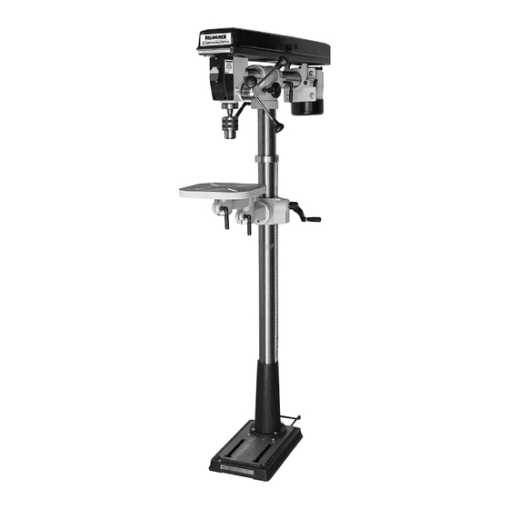
- Page 2 Palmgren Operating Manual & Parts List 9680341B & 9680342B DESCRIPTION MODEL 9680342B FLOOR DRILL PRESS Palmgren Radial Arm Drill Presses feature a heavy cast iron base, A Head Assembly work table and head. Head moves 11” forward and backward using B Column Assembly a rack and pinion.
-
Page 3: Proposition 65 Warning
Palmgren Operating Manual & Parts List 9680341B & 9680342B • Lead from lead-based paints. SPECIFICATIONS • Crystalline silica from bricks and cement and other masonry products. MODEL 9680341B • Arsenic and chromium from chemically-treated lumber. Chuck size ......... 1-16mm, JT33 Your risk from these exposures vary, depending on how often you Spindle taper . - Page 4 • Rotate table assembly around column. Adjust ring as necessary to prevent binding of rack. • Attach crank handle onto worm gear shaft. Secure handle with screw, tighten screw on flat of worm gear shaft. Figure 3 – Mount Column Assembly to Base (9680341B)
- Page 5 Palmgren Operating Manual & Parts List 9680341B & 9680342B • Slide table bracket assembly with rack over column. Place bottom ASSEMBLY (CONTINUED) end of rack inside beveled edge of column flange. See Figure 7. • Slide retaining ring over column with beveled edge down. Posi-...
- Page 6 Palmgren Operating Manual & Parts List 9680341B & 9680342B ASSEMBLY (CONTINUED) MOUNT CHUCK AND ARBOR Refer to Figure 22, page 12. MOUNT HEAD ASSEMBLY • Be sure spindle, arbor and chuck tapers are clean and dry. Make Refer to Figures 9 and 10.
-
Page 7: Grounding Instructions
Palmgren Operating Manual & Parts List 9680341B & 9680342B Do not remove or alter grounding prong in any manner. In the INSTALLATION event of a malfunction or breakdown, grounding provides a path of least resistance for electrical shock. WARNING: Do not permit fingers to touch the terminals of plug MOUNT DRILL PRESS when installing or removing from outlet. - Page 8 Palmgren Operating Manual & Parts List 9680341B & 9680342B INSTALLATION (CONTINUED) ELECTRICAL CONNECTIONS WARNING: All electrical connections must be performed by a qualified electrician. Make sure unit is off and disconnected from power source while motor is mounted, connected, reconnected or anytime wiring is inspected.
- Page 9 Palmgren Operating Manual & Parts List 9680341B & 9680342B • To obtain more distance between chuck and table, the work OPERATION (CONTINUED) table can be rotated 180° and base can be used as a work sur- • To return head to 0° vertical position, loosen head angle lock face.
- Page 10 Palmgren Operating Manual & Parts List 9680341B & 9680342B MAINTENANCE WARNING: Turn switch off and remove plug from power source outlet before maintaining or lubricating your drill press V-BELT Replace V-belt when worn. LUBRICATION The ball bearings are lubricated at the factory and need no further lubrication.
-
Page 11: Troubleshooting
Palmgren Operating Manual & Parts List 9680341B & 9680342B TROUBLESHOOTING SYMPTOM POSSIBLE CAUSES CORRECTIVE ACTION Spindle does not turn 1. No power to drill press 1. Check wiring, fuse or circuit breaker 2. Defective switch 2. Replace switch 3. Defective motor 3. - Page 12 Palmgren Operating Manual & Parts List 9680341B & 9680342B 59 26 40 41 22 23 Figure 22 - Replacement Parts Illustration for Head Models 9680341B & 9680342B...
- Page 13 Palmgren Operating Manual & Parts List 9680341B & 9680342B REPLACEMENT PARTS LIST FOR HEAD MODELS 9680341B & 9680342B Ref. Ref. No. Description Part No. Qty. No. Description Part No. Qty. Chuck Key 9630535.01 Set Screw, 5 x 6mm Chuck with Key (incl. Ref No. 1) 9630536.01...
- Page 14 Palmgren Operating Manual & Parts List 9680341B & 9680342B Figure 23 - Replacement Parts Illustration for Base, Model 9680341B...
- Page 15 Palmgren Operating Manual & Parts List 9680341B & 9680342B REPLACEMENT PARTS LIST FOR BASE, MODEL 9680341B Ref. Description Part Number Qty. Base 9630898.01 Column Assembly 9630899.01 Socket Head Bolt Rack 9630902.01 Set Screw Crank and Handle Assembly 9630911.01 Rack Retaining Ring 9630908.01...
- Page 16 Palmgren Operating Manual & Parts List 9680341B & 9680342B Figure 24 - Replacement Parts Illustration for Base, Model 9680342B...
- Page 17 Palmgren Operating Manual & Parts List 9680341B & 9680342B REPLACEMENT PARTS LIST FOR BASE, MODEL 9680342B Ref. Description Part Number Qty. Base 9630912.01 Column Assembly 9630913.01 8-1.25 x 20mm Socket Head Bolt Rack 9630914.01 6-1.0 x 10mm Set Screw Crank and Handle Assembly 9630915.01...
- Page 18 Palmgren Operating Manual & Parts List 9680341B & 9680342B Service Record Palmgren 33” Radial Arm Bench Drill Press (9680341B) Date Maintenance Performed Replacement Components Required...
- Page 19 Palmgren Operating Manual & Parts List 9680341B & 9680342B Service Record Palmgren 33” Radial Arm Floor Drill Press (9680342B) Date Maintenance Performed Replacement Components Required...
- Page 20 9680341B & 9680342B PALMGREN WARRANTY C.H. Hanson / Palmgren warrants their products to be free of defects in material or workmanship. This warranty does not cover defects due directly or indirectly to misuse, abuse, normal wear and tear, failure to properly maintain the product, heated, ground or otherwise altered, or used for a purpose other than that for which is was intended.
Need help?
Do you have a question about the 9680341B and is the answer not in the manual?
Questions and answers