
Subscribe to Our Youtube Channel
Related Manuals for Palmgren 9680219


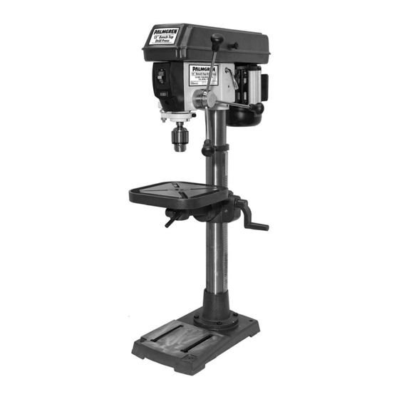
Summary of Contents for Palmgren 9680219
- Page 1 Operating Manual & Parts List 9680219 13˝ bench top Drill Press Read carefully and follow all safety rules and operating instructions before first use of this product. 9644895.02-0620...
-
Page 2: Getting Started
360° on a vertical axis. Work table surface is precision ground which features T-slots for secure, accurate mounting of workpiece and a coolant trough. Other features of the Palmgren drill press are an enclosed ball bearing quill assembly, quick belt change and tension mechanism, positive quick-adjust feed depth stop and a 1/3 HP, 1700 RPM motor. -
Page 3: Specifications
Palmgren Operating Manual & Parts List 9680219 SAFETY RULES (CONTINUED) • Avoid accidental start-up. Make sure that the switch is in the OFF position before plugging in. WARNING: Always follow proper operating procedures as defined in • Do not force tool. It will work most efficiently at the rate for this manual even if you are familiar with the use of this or similar tools. -
Page 4: Installing The Table
Palmgren Operating Manual & Parts List 9680219 ASSEMBLY WARNING: For your own safety, never connect plug to power source outlet until all assembly steps are completed. Combinatio n Square Medium Adjustable Wrench Figure 4 – Attach support lock and table crank. -
Page 5: Installing The Head
Palmgren Operating Manual & Parts List 9680219 ASSENBLY (CONTINUED) INSTALLING THE HEAD CAUTION: The head assembly weighs about 55 pounds. Carefully lift head. 1. Remove protective bag from head assembly and discard. Carefully lift head above column tube and slide it onto column making sure head slides down over column as far as possible. -
Page 6: Installing Feed Handles
Palmgren Operating Manual & Parts List 9680219 ASSENBLY (CONTINUED) ADJUSTING THE TABLE SQUARE TO HEAD NOTE: The combination square must be “true.” See “Tools Needed” at INSTALLING FEED HANDLES beginning of Assembly section for method. 1. Locate three (3) feed handles among loose parts. -
Page 7: Installation
Palmgren Operating Manual & Parts List 9680219 Do not use a 3-prong to 2-prong grounding adapter unless INSTALLATION permitted by local and national codes and ordinances. (A 3-prong to 2-prong grounding adapter is not permitted in POWER SOURCE Canada.) Where permitted, the rigid green tab or terminal on the side... -
Page 8: Operation
Palmgren Operating Manual & Parts List 9680219 Hex Bolt Figure 24 - Tilt adjustment hex bolt. Figure 22 – Wiring diagram. OPERATION Refer to Figures 23 through 30. STARTING AND STOPPING THE DRILL PRESS Refer to Figure 30, page 12. -
Page 9: Speed Adjustment
Palmgren Operating Manual & Parts List 9680219 OPERATION (CONTINUED) • Make sure that the drill is centered in the chuck. • Turn the chuck key clockwise to tighten the jaws. SPEED ADJUSTMENT WARNING: To avoid injury or accident by the chuck key ejecting Refer to Figure 28, speed chart inside belt guard and chart below. -
Page 10: Maintenance
Palmgren Operating Manual & Parts List 9680219 1. Lower quill assembly (Ref. No. 68 – 75) all the way down. MAINTENANCE 2. Apply lubricant around the inside of the hole in the spindle pulley (Ref. No. 89) . WARNING: Turn switch OFF and remove plug from outlet before 3. - Page 11 Palmgren Operating Manual & Parts List 9680219 NOTES...
- Page 12 Palmgren Operating Manual & Parts List 9680219 NOTES...
- Page 13 Palmgren Operating Manual & Parts List 9680219 NOTES...
- Page 14 Palmgren Operating Manual & Parts List 9680219 Figure 30 - Parts illustration for 13˝ Bench Top Drill Press.
- Page 15 Palmgren Operating Manual & Parts List 9680219 REPLACEMENT PARTS LIST FOR 13˝ BENCH TOP DRILL PRESS Ref. Ref. Description Part No. Qty. Description Part No. Qty. BASE 9644896.01 SCREW PAN, M6 x 12 SUPPORT COLUMN 9644897.01 KNOB 9644942.01 SCREW HEX HEAD, M10 x 40...
- Page 16 PALMGREN WARRANTY C.H. Hanson / Palmgren warrants their products to be free of defects in material or workmanship. This warranty does not cover defects due directly or indirectly to misuse, abuse, normal wear and tear, failure to properly maintain the product, heated, ground or otherwise altered, or used for a purpose other than that for which is was intended.
Need help?
Do you have a question about the 9680219 and is the answer not in the manual?
Questions and answers