Table of Contents

Related Manuals for Palmgren 80177


Summary of Contents for Palmgren 80177
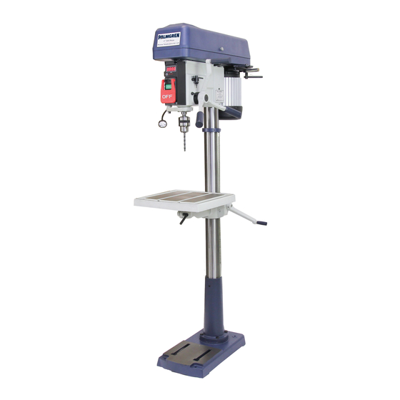
- Page 1 Palmgren Operating Manual & Parts List 80177 operating manual & parts list 80177 17" FLOOR MODEL DRILL PRESS WITH SINGLE / THREE PHASE Read carefully and follow all safety rules and operating instructions before first use of this product.
-
Page 2: Specifications
In order to ensure proper fit and operation the coating must be removed. Remove coating with mild solvents such as mineral spirits Palmgren Drill Presses feature a heavy cast iron base, column collar, and a soft cloth. Nonflammable solvents are recommended. After work table and head. - Page 3 Palmgren Operating Manual & Parts List 80177 WORK AREA SHOULD BE READY FOR JOB ● Feed work into a bit or cutter against the direction of rotation of bit or cutter. ● Keep work area clean. Cluttered work areas and work benches ● Turn the machine off if it jams.
-
Page 4: Installation
Palmgren Operating Manual & Parts List 80177 INSTALL THE HEAD INSTALLATION Refer to Figure 9/10. WARNING: Although compact, the drill press head assembly MOUNT DRILL PRESS is heavy. Two people are required to mount the drill press head ● Drill press must be mounted to flat level surface. Use shims or assembly onto the column. -
Page 5: Operation
Palmgren Operating Manual & Parts List 80177 Green (or green and yellow) conductor in cord is the grounding wire. For three phase: Drill press requires a 120 volt, 60 Hz power source. If repair or replacement of the electric cord or plug is necessary, do not connect the green (or green and yellow) wire to a live terminal. -
Page 6: Speed Adjustments
Palmgren Operating Manual & Parts List 80177 SPEED ADJUSTMENTS Refer to Figures 5 and 8. WARNING: Be sure drill press is turned off and is disconnected from power source before adjusting speeds. ● To change spindle speed, loosen motor lock handle (Ref. No. 187), pivot the motor toward front of drill press. This will loosen the belt and permit relocating the belt to the desired pulley groove for the required spindle speed (See Figure 5). -
Page 7: Maintenance
Palmgren Operating Manual & Parts List 80177 REMOVE THE CHUCK ● Apply lubricant to rack and pinion gear (Figure 7, Ref. Nos. 13 & 34) on column and table assembly. Refer to Figure 8. ● With the switch “OFF” and the unit unplugged, adjust the depth CLEAN MOTOR stop nut (Ref. -
Page 8: Troubleshooting
Palmgren Operating Manual & Parts List 80177 TROUBLESHOOTING SYMPTOM POSSIBLE CAUSES CORRECTIVE ACTION Spindle does not turn 1. No power to drill press 1. Check wiring, fuse or circuit breaker 2. Defective switch 2. Replace switch 3. Defective motor 3. Replace motor... - Page 9 Palmgren Operating Manual & Parts List 80177 Service Record Palmgren 17" Floor Modle Drill Press DATE MAINTENANCE PERFORMED REPLACEMENT PARTS REQUIRED...
- Page 10 Palmgren Operating Manual & Parts List 80177 NOTES...
- Page 11 Palmgren Operating Manual & Parts List 80177 NOTES...
- Page 12 Palmgren Operating Manual & Parts List 80177 Figure 7 - Replacement Parts Illustration for Base (Single & Three Phase)
- Page 13 Palmgren Operating Manual & Parts List 80177 REPLACEMENT PARTS LIST FOR BASE Ref. Part No. Description Qty. Base 9632113.05 Columm holder ass'y 9632114.05 M10*1.5-40 Hex. hd. bolt Rack 9632179.05 Location pin 9631972.05 1/4*20UNC T=4.7 Hex. nut 5/8-11UNC-1 Hex. hd. bolt Table lock handle 9632117.05...
- Page 14 Palmgren Operating Manual & Parts List 80177 105 (~) 106 (3~) 189 (~) 190 (3~) 118 (~) 119 (3~) Figure 8 - Replacement Parts Illustration for Spindle and Drive (Single & Three Phase)
- Page 15 Palmgren Operating Manual & Parts List 80177 REPLACEMENT PARTS LIST FOR SPINDLE AND DRIVE Ref. Ref. No. Description Part No. Qty. No. Description Part No. Qty. Feed shaft ass'y 9632140.10 160 φ22.5 Pulley set nut 9632126.05 M10*1.5 T=8 Hex. nut 163 V-ribbed belt (poiyourethane) 9632180.10...
- Page 16 Palmgren Operating Manual & Parts List 80177 Figure 9 - Replacement Parts Illustration for Head (Single Phase)
- Page 17 Palmgren Operating Manual & Parts List 80177 REPLACEMENT PARTS LIST FOR HEAD (Single Phase) Ref. Ref. No. Description Part No. Qty. No. Description Part No. Qty. φ2.3-5 Drive screw Label Lead wire ass'y 9600068.00 Hall sensor ass'y 9632042.05 Lead wire ass'y 9600069.00...
- Page 18 Palmgren Operating Manual & Parts List 80177 Figure 10 - Replacement Parts Illustration for Head (Three Phase)
- Page 19 Palmgren Operating Manual & Parts List 80177 REPLACEMENT PARTS LIST FOR HEAD (Three Phase) Ref. Ref. No. Description Part No. Qty. No. Description Part No. Qty. φ2.3-5 Drive screw Label Lead wire ass'y 9600068.00 Hall sensor ass'y 9632042.05 Lead wire ass'y 9600069.00...
-
Page 20: Warranty
● Accessories – 1 year The obligation of Palmgren is limited solely to the repair or replacement, at our option, at its factory or authorized repair agent of any part that should prove deficient. Purchaser must lubricate and maintain the product under normal operating conditions at all times.
Need help?
Do you have a question about the 80177 and is the answer not in the manual?
Questions and answers