
Related Manuals for Go Power GP-PWM-10-FM


Summary of Contents for Go Power GP-PWM-10-FM
- Page 1 GP-PWM-10-FM (with LiFePO ________________________________________________________________________ GP-PWM-10-FM User Manual © 2019 Go Power!
-
Page 2: Table Of Contents
Display Symbols USB Charging 10.0 Frequently Asked Questions (FAQs) 11.0 Troubleshooting Problems 11.1 Problems with the Display 11.2 Problems with Voltage 11.3 Problems with Current 12.0 Limited Warranty 12.1 Repair and Return Information 13.0 Installation Template © 2018 Go Power! -
Page 3: Installation Overview
1.2 System Voltage and Current The GP-PWM-10-FM is intended for use at 12 VDC nominal system voltage and is rated for a maximum continuous DC input current of 12.5A and input voltage of 35VDC. -
Page 4: Low Voltage Disconnect Function (Usb Port)
Charge, and Amp Hours Charged Since Operating Consumption 6 mA Last Reset (Display backlight off) • Reverse Polarity Battery Types Supported Vented & Sealed Lead Acid (GEL, Protected • Temperature AGM, Flooded, etc.). Lithium (LiFePO © 2018 Go Power! -
Page 5: Important Safety Instructions
PV Short Circuit, Over Current 2.0 IMPORTANT SAFETY INSTRUCTIONS SAVE THESE INSTRUCTIONS THIS MANUAL CONTAINS IMPORTANT INSTRUCTIONS FOR MODEL GP-PWM-10-FM THAT SHOULD BE FOLLOWED DURING INSTALLATION AND MAINTENANCE OF THE GP- PWM-10-FM. Electricity can be very dangerous. Installation Disconnect all... - Page 6 IMPORTANTES INSTRUCTIONS DE SECURITE CONSERVEZ CES INSTRUCTIONS CE MANUAL CONTIENT DES INSTRUCTIONS IMPORTANTES POUR LE MODÈLE GP-PWM-10-FM QUI DOIVENT ÊTRE SUIVIES PENDANT L’INSTALLATION ET L’ENTRETIEN DU GP- PWM-10-FM. © 2018 Go Power!
- Page 7 1,25. Le courant du système qui en résulte nominal ne doit pas excéder 12,5 A. Si votre système maximum du solaire dépasse cette valeur, veuillez contacter GP-PWM-10-FM votre revendeur pour obtenir un régulateur plus approprié. © 2018 Go Power!
-
Page 8: Tools And Materials Needed
The wire from the solar array most commonly enters the RV through the fridge vent on the roof or by using the Go Power! Cable Entry Plate (sold separately) that allows installers to run wires through any part of the roof. -
Page 9: Installation Instructions
2. Complete the installation of the solar modules. If this GP-PWM-10-FM was purchased as part of a Go Power! Solar Power Kit, follow the Installation Guide provided. Otherwise, follow manufacturer’s instructions for solar module mounting and wiring. - Page 10 Wiring the GP-PWM-10-FM. Wire the GP-PWM-10-FM according to the wiring schematic in Section 6. Run wires from the solar array and the batteries to the location of the GP-PWM-10-FM. Keep the solar array covered with an opaque material until all wiring is completed.
- Page 11 6. Mounting the GP-PWM-10-FM. Mount the GP-PWM-10-FM to the wall using the included four mounting screws. IMPORTANT: You must set the battery type on the GP-PWM-10-FM before you begin to use the controller (follow steps in Section 7). The default battery setting is for AGM/LiFePO batteries.
-
Page 12: Wiring Diagram
IMPORTANT: This diagram is valid only for version 1.5 and newer. Version 1.4 and older have different terminal locations. The GP-PWM-10-FM Maximum 12.5A rating is based on a 10 amp total maximum short circuit current rating (Isc) from the parallel solar modules nameplate ratings. -
Page 13: Operating Instructions
GP-PWM-10-FM 7.0 Operating Instructions 7.1 Power Up When the GP-PWM-10-FM is connected to the battery, the controller will go into Power Up mode. Icons Displayed: All segments of the numerical display; backlight blinks. Depending on the battery voltage when the GP-PWM-10-FM Power Up occurs, the controller may do a Boost Charge or quickly go into Float Charge. -
Page 14: Battery Charging Profile Chart
Auto Equalize: The GP-PWM-10-FM has an automatic equalize feature that will charge and recondition your batteries at least once a month at a higher voltage to ensure that any excess sulfation is removed. - Page 15 Push the B Button to show the PV charging current. Icons Displayed: Ampere Symbol (A), Battery SOC Push the B Button to show the battery state of charge (shown as a percentage). Icons Displayed: Battery SOC, Percent Symbol © 2018 Go Power!
-
Page 16: Resetting The Ampere Hours Charged
(kAh) 7.5 Resetting the ampere hours charged To reset the count of ampere hours charged, toggle to the ampere hours charged. Press and hold the A Button for 6 seconds to reset the counter to zero. © 2018 Go Power! -
Page 17: Errors
SOC symbol will show the text “LOW” beneath it. The controller will continue operating in this condition and will only stop operating if the voltage drops below 9 volts. Icons Displayed: Battery SOC Symbol, LOW © 2018 Go Power! -
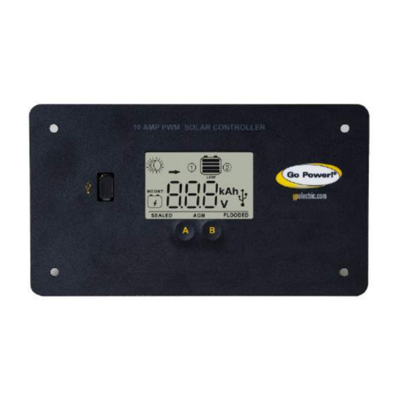
Page 18: Display Symbols
Whole display will start to blink Battery voltage > 15.5 VDC Battery State of Charge Symbol Battery Voltage Shows only after full Boost or Equalization Cycle >= 12.6 VDC >= 11.8 -12.6 VDC > 11.0 -11.8 VDC © 2018 Go Power! -
Page 19: Usb Charging
<= 11.0 VDC USB Charging The GP-PWM-10-FM offers a standard USB connector for delivering 5.0 VDC to small mobile appliances such as cell phones, tablets or small music players. This charging port is capable of supplying up to 1500 mA of current. - Page 20 There may be a slight difference between the battery voltage displayed on the GP-PWM-10-FM display and the battery voltage measured at the battery terminals. When troubleshooting using a voltmeter, check both the battery voltage at the GP-PWM-10-FM controller terminals and battery voltage at the battery terminals.
-
Page 21: Troubleshooting Problems
Battery or fuse connection and/or solar array connection (Daytime only) or battery or fuse connection (Nighttime only). How to tell: 1. Check the voltage at the controller battery terminals with a voltmeter and compare with a voltage reading at the battery terminals. © 2018 Go Power! -
Page 22: Problems With Voltage
Excessive voltage drop from batteries to controller due to loose connections, small wire gauge, or both. How to tell: 1. Check the voltage at the controller battery terminals with a voltmeter and compare with the voltage reading at the battery terminals. © 2018 Go Power! -
Page 23: Problems With Current
Battery capacity deteriorates with age and extreme use. Wait for the battery voltage to fall. Batteries self-discharge over time. 11.3 Problems with Current Current Reading: 0 A Time of Day: Daytime, clear sunny skies © 2018 Go Power! - Page 24 (1) Battery State of Charge screen is close to 100% and the Sun and Battery icons are present with an arrow in between. (2) Check that the modules and batteries are configured correctly. Check all wiring connections. © 2018 Go Power!
- Page 25 (4) If the open circuit voltage of a non-connected 12-volt module is lower than the manufacturer’s specifications, the module may be faulty. Check for blown diodes in the solar module junction box, which may be shorting the power output of the module. © 2018 Go Power!
-
Page 26: Limited Warranty
GP-PWM-10-FM 12.0 Limited Warranty Go Power! warrants the GP-PWM-10-FM for a period of five (5) years from the date of shipment from its factory. This warranty is valid against defects in materials and workmanship for the five (5) year warranty period. - Page 27 GP-PWM-10-FM © 2018 Go Power!
- Page 28 GP-PWM-10-FM © 2019 GO POWER!® MOBI_MAN_GP-PWM-10-FM_RevD gpelectric.com © 2018 Go Power!
Need help?
Do you have a question about the GP-PWM-10-FM and is the answer not in the manual?
Questions and answers