Table of Contents
Advertisement
Quick Links
INSTALLER:
Leave this manual with the appliance.
CONSUMER:
Retain this manual for future reference.
WARNING
If the information in this manual is not
followed exactly, a fire or explosion may
result causing property damage, personal
injury or loss of life.
— do not store or use gasoline or other
flammable vapors and liquids in the
vicinity of this or any other appliance.
— WHAT TO dO IF YOU SMELL GAS
•
Do not try to light any appliance.
•
Do not touch any electrical switch;
do not use any phone in your building.
•
Immediately call your gas supplier
from a neighbor's phone. Follow
the gas supplier's instructions.
•
If you cannot reach your gas
supplier, call the fire department.
— Installation and service must be
performed by a qualified installer,
service agency or the gas supplier.
WARNING
"FIRE, EXPLOSION, ANd ASPHYXIATION HAZARd
Improper adjustment, alteration, service,
maintenance or installation of this heater or
its controls can cause death or serious injury.
Read and follow instructions and precautions
in User's Information Manual provided with
this heater."
This is an unvented gas-fired heater. It uses air
(oxygen) from the room in which it is installed.
Provisions for adequate combustion and
ventilation air must be provided.
Refer to pages 15.
INSTALLATION INSTRUCTIONS
This appliance may be installed in an aftermarket,
permanently located, manufactured (mobile)
home, where not prohibited by local codes.
This appliance is only for use with the type of gas
indicated on the rating plate. This appliance is not
convertible for use with other gases.
UL FILe No. mh46389
This series is design certified in
accordance with American National
Standard Institute (ANSI) Z21.11.2
by the Canadian Standards
Association Laboratories (CSA)
as an Unvented Room Fireplace
and should be installed according
to these instructions.
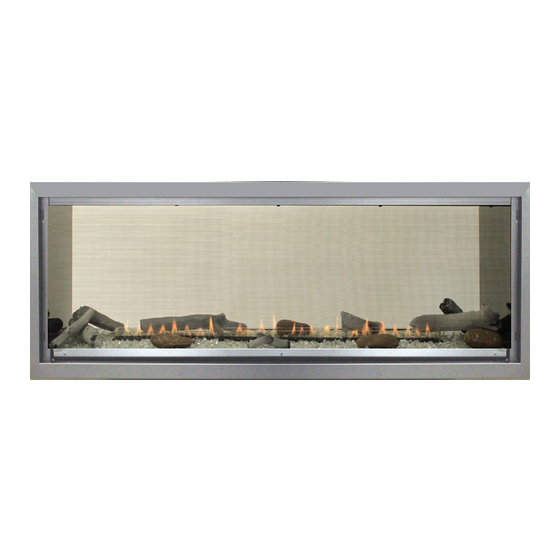
CONTEMPORARY
LINEAR VENT-FREE
GAS FIREPLACE MOdEL
VFLB48SP90(N,P)-1
GAS-FIRED
Page 1
Advertisement
Table of Contents

Related Manuals for Boulevard VFLB48Sp90N-1


Summary of Contents for Boulevard VFLB48Sp90N-1
- Page 1 INSTALLATION INSTRUCTIONS INSTALLER: CONTEMPORARY Leave this manual with the appliance. LINEAR VENT-FREE CONSUMER: GAS FIREPLACE MOdEL Retain this manual for future reference. VFLB48SP90(N,P)-1 WARNING If the information in this manual is not followed exactly, a fire or explosion may result causing property damage, personal injury or loss of life.
-
Page 2: Table Of Contents
TABLE OF CONTENTS SECTION PAGE Before You Start ............................3 Carton Contents ............................4 hardware Pack ............................5 Important Soot Prevention Steps ....................... 6 Product Specifications ..........................7 homeowner Reference Information ......................7 optional Accessories ..........................8 Introduction ..............................9 Important Information .......................... -
Page 3: Before You Start
BEFORE YOU START SAMPLE WARNINGS ANd dEFINITIONS: spacers, and secured to combustible framing using the framing brackets provided. dANGER This fireplace requires an easily accessible gas shutoff valve be installed in the gas supply line prior to its entry to the fireplace. Indicates a hazardous situation which, if not avoided, will result in death or serious injury. -
Page 4: Carton Contents
CARTON CONTENTS Items not shown to scale. VFLB48SP90 SERIES VFLB48SP90 SERIES Index Quantity Index Quantity description description Supplied Supplied Fireplace Junction Box Cover Non-combustible Board - top AC Adaptor Non-combustible Board - Side Burner Glass Barrier Screen Assembly Side Burner Glass Romex Connector hardware Pack Bushing... -
Page 5: Hardware Pack
HARdWARE PACK HARdWARE PACK CONTENTS #10-16 X ½” STAINLESS PHILLIPS HEAD SCREW #10-32 X ½” HEX HEAD SCREW #8 X 1” PHILLIPS SELF-DRILLING DRYWALL SCREW NAILING FLANGE (Not to scale) description Quantity Supplied #10-16 x 1/2 Phillips Stainless Screw #10-32 X 1/2 Phillips hex head Screw #8 x 1 Inch Self-Drilling Drywall Screw Nailing Flange See Parts Lists on page 47 for replacement parts. -
Page 6: Important Soot Prevention Steps
IMPORTANT SOOT PREVENTION STEPS IMPORTANT NOTICE INStALLeR - SeRVICe PeRSoN - homeoWNeR SOOT MAY BE CREATEd IF THE FOLLOWING dIRECTIONS ARE NOT FOLLOWEd Ensure the air shutter is set to the specification. See WARNING Figure 1 and Tables 1 and 2 on page 7. Failure to keep the primary air openings of the burner clean ensure burner, venturi, and air shutter are free of dirt, lint, may result in sooting and property damage. -
Page 7: Product Specifications
PROdUCT SPECIFICATIONS VFLB48SP90P (PROPANE GAS) VFLB48SP90N (NATATURAL GAS) Input BtU/hR maximum 36,000 36,000 Input BtU/hR minimum 28,000 25,000 Orifice 1.75mm Notice: Air shutter settings are factory set and may not be altered. GAS SUPPLY PRESSURES (inches water column) Gas Type Maximum Minimum Manifold... -
Page 8: Optional Accessories
OPTIONAL ACCESSORIES PART NUMBER dESCRIPTION VFLB48SP DF481VBL Decorative Front, Beveled, 3/4 inch, Black DF482VBL Decorative Front, Beveled, 1 1/2 inch, Black VBP48BLKR Liner with Burner Cover - Black Reflective LS60ShF Log Set - 22 Piece DG1GC Decorative Glass Droplets - 1/2 inch Glacier Ice (one kit per one square foot) DG1SL Decorative Glass Droplets - 1/2 inch Sangria Luster (one kit per one square foot) DG1NXS... -
Page 9: Introduction
INTROdUCTION INSTRUCTIONS TO INSTALLER The term qualified agency means any individual, firm, corporation or company which either in person or through a representative Leave instruction manual with owner after installation. is engaged in and is responsible for (a) the installation or Have owner register online or fill out and mail the Product replacement of gas piping or (b) the connection, installation, Registration Card supplied with the unvented fireplace. -
Page 10: Important Information
IMPORTANT INFORMATION MAINTENANCE ANd SERVICE WARNING Although the frequency of servicing and maintenance will depend Read and follow these safety precautions prior to operating on use and the type of installation, a qualified service technician this appliance. Failure to follow these precautions may should perform an appliance checkup at the beginning of each result in death, injury, or property damage. -
Page 11: Important Safety Information
IMPORTANT SAFETY INFORMATION WARNING dANGER When used without adequate combustion and ventilation air, The installer is responsible for the verifying the correct appliance may give off CARBON MONOXIdE, an odorless, position of the air shutter and adjusting it if required. If not poisonous gas. -
Page 12: Safety Information For Users Of Propane Gas
SAFETY INFORMATION FOR USERS OF PROPANE GAS Propane is a flammable gas which can cause fires and SOME POINTS TO REMEMBER explosions. In its natural state, propane is odorless and colorless. • Learn to recognize the odor of Propane Gas. Your local You may not know all the following safety precautions which can Propane Gas Dealer can give you a Scratch and Sniff protect both you and your family from an accident. -
Page 13: Important Installation Guidelines
IMPORTANT INSTALLATION GUIdELINES PROPER PRIMARY AIRFLOW INTO BURNER TELEVISION CONSIdERATIONS For proper burner operation and flame appearance, the flow of Installing a television above a fireplace has become increasingly primary air into the venturi tube, located at the gas inlet of the popular;... -
Page 14: Provisions For Adequate Combustion And Ventilation Air
PROVISIONS FOR AdEQUATE COMBUSTION ANd VENTILATION AIR This heater shall not be installed in a confined space unless provisions DIVIDER are provided for adequate combustion and ventilation air. The National Fuel Gas Code defines a confined space as a space whose per kw) volume is less than 50 cubic feet per 1,000 Btu per hour (4.8m FIREPLACE... - Page 15 PROVISIONS FOR AdEQUATE COMBUSTION & VENTILATION AIR (CONT'd) If the area in which the heater may be operated is smaller than that Ventilation Air From Outdoors defined as an unconfined space, provide adequate combustion and Provide extra fresh air by using ventilation grills or ducts. two ventilation air by one of the following methods: permanent openings must be provided;...
-
Page 16: Fireplace Dimensions
FIREPLACE dIMENSIONS ELECTRICAL ELECTRICAL ACCESS ACCESS ELECTRICAL ELECTRICAL ACCESS ACCESS GAS LINE ACCESS GAS LINE ACCESS GAS LINE ACCESS GAS LINE ACCESS HOLES IN STANDOFF HOLES IN STANDOFF GAS LINE ACCESS GAS LINE GAS LINE ACCESS ACCESS VFLB48SP INdEX GAS LINE dIMENSION dESCRIPTION dIMENSION LETTER... -
Page 17: Clearances
CLEARANCES WARNING do not put screws through large non-combustible board and into the fireplace. Attach screws only in standoffs. MANTEL CLEARANCES 36” MINIMUM CLEARANCE TO CEILING AND ENCLOSURE TOP NON-COMBUSTIBLE BOARD 22 1/2” REQUIRED IN THIS AREA (SUPPLIED WITH FIREPLACE) FINISHED WALL FINISHED WALL FLAT MANTEL SHELF... -
Page 18: Framing Options
FRAMING OPTIONS REAd THIS BEFORE FRAMING IS BEGUN OPTION 2 allows the non-combustible board to be installed flush with the fireplace face. Then tile, stone, or other non-combustible materials This see-through fireplace can be installed with different looks for are installed within 1/16 inch of the fireplace opening. (Increase the Faces A and B –... -
Page 19: Adding Nailing Flanges And Standoff Brackets
AddING NAILING FLANGES ANd STANdOFF BRACKETS At the top and bottom of the fireplace, use pliers to bend each side standoff 90 degrees away from the cabinet. See Figure 15. Figure 18 - OPTION 2 WARNING TWO MAN LIFT RULE! Repeat on opposite side. - Page 20 AddING NAILING FLANGES ANd STANdOFF BRACKETS 9a. OPTION 1 - Secure the brackets to the fireplace top with 10a. OPTION 1 - Secure standoff brackets with drywall screws to the screws. There are holes located in the top of the fireplace for framed opening above the fireplace as shown in Figure 23.
-
Page 21: Utility Installation
UTILITY INSTALLATION Remove barrier screen assembly from fireplace by lifting up TESTING GAS SUPPLY PRESSURE slightly and pulling out. Set aside. Remove the burner cover by Notice: the gas controls are equipped with a captured screw- lifting it up and out. Set aside. type pressure test point. - Page 22 UTILITY INSTALLATION (CONT'd) JUNCTION BOX WIRING INSTALLATION LEFT (VALVE) SIDE A factory-installed junction box is located at the lower left corner OF FIREPLACE inside the firebox. For 120V electrical requirements install the electrical receptacles into the junction box. FRONT OF Remove the burner cover by lifting straight up and then FIREPLACE forward.
- Page 23 UTILITY INSTALLATION (CONT'd) Remove the electrical access cover panel from the left end Install the Junction box cover. See Figure 34. of the fireplace. See Figure 32. Figure 32 Run 14/2 Nm-B with ground or 12/2 Nm-B with ground wire through the electrical access panel into the Junction box.
- Page 24 UTILITY INSTALLATION (CONT'd) 14. Install the provided plastic bushing in the opening where 16. Place batteries in remote receiver and in the remote control the wires exit the fireplace. See Figure 36 (left side), or using instructions provided. Place the switch slider to the Figure 37 (right side).
- Page 25 UTILITY INSTALLATION (CONT'd) WIRING DIAGRAM IGNITOR NOT USED SENSOR PILOT GREEN BLUE ORANGE WHITE REMOTE RECEIVER YELLOW + ON REMOTE - OFF EXTENSION HARNESS BLACK BLACK NOT USED GAS CONTROL VALVE (GND) AC/DC POWER ADAPTOR ELECTRONIC CONTROL MODULE NOT USED the wire terminals shown in Figure 40 are not connected.
-
Page 26: Installation Option 1 - Clean Face
INSTALLATION OPTION 1 - CLEAN FACE Notice: the steps on pages 27 and 28 are for installation oPtIoN 1 - Clean Face. This type of installation will allow for finishing around the fireplace face with high-temperature paint. See pages 30 and 31 for installing the fireplace for installation oPtIoN 2 - Flush mount. Page 26 40215-3-0220... -
Page 27: Option 1 - Clean Face (Non - Combustible Board Installation)
OPTION 1 - CLEAN FACE ( NON-COMBUSTIBLE BOARd INSTALLATION ) Notice: If installing a decorative front, an offset between the finishing materials and fireplace opening is required. Refer to the CEILING ENCLOSURE installation instructions provided with the decorative front before framing the opening. - Page 28 OPTION 1 - CLEAN FACE ( NON-COMBUSTIBLE BOARd INSTALLATION ) Install non-combustible board provided with the fireplace. See Figure 43. • Do not attach non-combustible board to the fireplace. Attach non-combustible board only to framing and standoffs. • Space non-combustible board 1/16 inch off of fireplace opening flanges to allow for expansion during operation.
-
Page 29: Installation Option 2 - Flush Mount
INSTALLATION OPTION 2 - FLUSH MOUNT Notice: the steps on pages 30, and 31 are for installation oPtIoN 2 - Flush mount. this type of installation will allow for applying tile, marble, stone or other non-combustible materials over the face of the fireplace cabinet up to the flange opening. See pages 27 and 28 for installation oPtIoN 1 - Clean Face. -
Page 30: Option 2 - Flush Face (Non - Combustible Board Installation)
OPTION 2 - FLUSH FACE ( NON-COMBUSTIBLE BOARd INSTALLATION ) Notice: If installing a decorative front, an offset between the finishing materials and fireplace opening is required. Refer to the CEILING ENCLOSURE installation instructions provided with the decorative front before framing the opening. - Page 31 OPTION 2 - FLUSH FACE (NON-COMBUSTIBLE BOARd INSTALLATION) Install non-combustible board provided with the fireplace. See Figure 47. • Do not attach non-combustible board to the fireplace face. Attach non-combustible board only to the framing and standoffs. • Space non-combustible board 1/16 inch off of fireplace opening flanges to allow for expansion during operation.
-
Page 32: Completing Installation
COMPLETING INSTALLATION Retrieve the 4 glass panels and install on front, back and WARNING both sides of burner. See Figure 50. Failure to position the parts in accordance with the diagrams and instructions below or failure to use only parts specifically approved for use with this fireplace may result in property damage or personal injury. - Page 33 COMPLETING INSTALLATION (CONT'd) Apply the accessory decorative glass or rocks to the shaded area only. See Figure 51. Use enough to cover the area of the fireplace, but do not allow the media to reach higher than the flange surrounding the burner. Never place decorative media inside the flange surrounding the burner itself.
-
Page 34: Lighting Instructions
LIGHTING INSTRUCTIONS FOR YOUR SAFETY REAd BEFORE LIGHTING WARNING If you do not follow these instructions exactly, a fire or explosion may result causing property damage, personal injury or loss of life. A. this appliance has a pilot which can be lit by hand or by C. -
Page 35: Pilot Flame Characteristics
PILOT FLAME CHARACTERISTICS Figure 54 shows a correct pilot flame pattern. The correct flame IGNITOR will be blue and will extend beyond the flame sensor. The flame will surround the flame sensor just below the tip. A slight yellow flame may occur where the pilot flame and main burner flame SENSOR meet. -
Page 36: Proflame - Ip Control System
PROFLAME - IP CONTROL SYSTEM TRANSMITTER (REMOTE CONTROL WITH LCd dISPLAY) TECHNICAL dATA The Proflame Transmitter uses a streamline design with a simple Remote Control button layout and informative LCD display. See Figure 57. Supply voltage 4.5 V (three 1.5 V AAA batteries) the transmitter is powered by 3 AAA type batteries. - Page 37 PROFLAME - IP CONTROL SYSTEM (CONT'd) RECEIVER The Proflame Receiver Figures 58 and 59 connects directly to the gas valve and stepper motor with a wiring harness. the REMOTE Receiver is powered by 4 AA type batteries. the Receiver RECEIVER accepts commands via radio frequency from the transmitter to SWITCH operate the fireplace in accordance with the particular Proflame...
- Page 38 PROFLAME - IP CONTROL SYSTEM (CONT'd) INITIALIZING THE SYSTEM TURN ON THE FIREPLACE Install 4 AA batteries into the receiver located behind the wall Press the oN/oFF Button. the transmitter display will show all plate. See Figure 60. Note the polarity of battery and insert into active Icons on the screen.
- Page 39 PROFLAME - IP CONTROL SYSTEM (CONT'd) REMOTE FLAME CONTROL The remote has six flame levels. With the system on, and the flame level at maximum, each time you press the down arrow button will reduce the flame height by one step until the flame is turned off.
- Page 40 PROFLAME - IP CONTROL SYSTEM (CONT'd) THERMOSTAT OPERATION SMART THERMOSTAT (TRANSMITTER OPERATION) the Remote Control can operate as a room thermostat. the The Smart Thermostat function adjusts the flame height in thermostat can be set to a desired temperature to control the accordance to the difference between the set point temperature comfort level in a room.
- Page 41 PROFLAME - IP CONTROL SYSTEM (CONT'd) BUTTON LOCK RECEIVER this function will lock the buttons to prevent unsupervised When the receiver batteries are low, no beep will be emitted operation. when it receives an oN/oFF command from the transmitter. to lock the remote, press the moDe and the UP arrow button at Replace the batteries.
-
Page 42: Cleaning And Servicing
CLEANING ANd SERVICING Annual inspection and cleaning by the dealer or qualified service If intermittent pilot fireplace stops working, clean flame sensor B Figure 75 with a damp cloth. technician is recommended to prevent malfunction. tURN oFF FIRePLACe AND ALLoW to CooL BeFoRe If intermittent pilot ignitor does not spark, clean ignitor C CLeANING. -
Page 43: Troubleshooting
TROUBLESHOOTING BRIEF dESCRIPTION OF THE COMPONENTS the Digital Fireplace Control (DFC) is an automatic gas ignition system based on a single micro-controller core. this control manages all functions related to ignition, flame sensing and supervision for atmospheric applications. the DFC can be set to provide continuous or intermittent ignition control sequences and flame monitoring with safety shutdown in case of failure. - Page 44 TROUBLESHOOTING (CONT'd) PROBLEM OBSERVEd POSSIBLE CAUSE CORRECTIVE MEASURE What To do If You Smell Gas Gas odor during setup Gas Leak Do not try to light any appliance. Do not touch any electrical switch; Do not use any phone in your building. Immediately call your gas supplier from a Gas odor before first ignition Gas Leak...
- Page 45 TROUBLESHOOTING (CONT'd) PROBLEM OBSERVEd POSSIBLE CAUSE CORRECTIVE MEASURE Flame sensor dirty Clean pilot sensor Low gas pressure Check gas supply pressure Not enough fresh air for pilot open door or window - ventilate Clogged or dirty burner ports Clean burner ports (For fireplace equipped with optional Move (optional) remote away from fireplace thermostat or thermostat remote) Room...
-
Page 46: Vflb48Sp90 Exploded View
VFLB48SP90 - EXPLOdEd VIEW BURNER ASSEMBLY WALL PANEL ASSEMBLY WARNING Failure to position the parts in accordance with these diagrams or failure to use only parts specifically approved with this heater may result in property damage or personal injury. Page 46 40215-3-0220... -
Page 47: Vflb48Sp90 Parts List
VFLB48SP90 - PARTS LIST PART NO. PART NO. INdEX INdEX dESCRIPTION dESCRIPTION VFLB48SP VFLB48SP R11597 tubing Ferrule - Pilot 36787 Standoff Bracket (6 Required) R11598 tubing Nut - Pilot 40224 Non-Combustible Board - top (2 Required) R1978 tubing Nut & Ferrule - Valve Non-Combustible Board - Side 40222 (4 Required) -
Page 48: Service Technician Notes
SERVICE TECHNICIAN NOTES date dealer Name Service Technician Name Service Performed/Notes Page 48 40215-3-0220... - Page 49 SERVICE TECHNICIAN NOTES date dealer Name Service Technician Name Service Performed/Notes 40215-3-0220 Page 49...
-
Page 50: Master Parts Distributor List
Please note: master Parts Distributors are independent businesses that stock the most commonly ordered original equipment repair parts for heaters, Grills, and Fireplaces manufactured by empire Comfort Systems Inc. Dey Distributing F. W. Webb Company 1401 Willow Lake Boulevard 200 Locust Street Vadnais heights, mN 55101 hartford, Ct 06114... -
Page 51: Warranty
WARRANTY Empire Comfort Systems Inc. warranties this hearth product to be free from defects at the time of purchase and for the periods specified below. Hearth products must be installed by a qualified technician and must be maintained and operated safely, in accordance with the instructions in the owner’s manual. - Page 52 Empire Comfort Systems Inc. Belleville, IL If you have a general question about our products, please e-mail us at info@empirecomfort.com. If you have a service or repair question, please contact your dealer. www.empirecomfort.com...
Need help?
Do you have a question about the VFLB48Sp90N-1 and is the answer not in the manual?
Questions and answers