Table of Contents
Advertisement
Quick Links
INSTALLER:
Leave this manual with the appliance.
CONSUMER:
Retain this manual for future reference.
If the information in this manual is not
followed exactly, a fire or explosion may
result causing property damage, personal
injury or loss of life.
— do not store or use gasoline or other
flammable vapors and liquids in the
vicinity of this or any other appliance.
— WHAT TO dO IF YOU SMELL GAS
•
Do not try to light any appliance.
•
Do not touch any electrical switch; do
not use any phone in your building.
•
Immediately call your gas supplier
from a neighbor's phone. Follow the
gas supplier's instructions.
•
If you cannot reach your gas supplier,
call the fire department.
— Installation and service must be
performed by a qualified installer,
service agency or the gas supplier.
This is an unvented gas-fired heater. It uses air
(oxygen) from the room in which it is installed.
Provisions for adequate combustion and
ventilation air must be provided.
Refer to pages 15.
"FIRE, EXPLOSION, ANd ASPHYXIATION HAZARd
Improper adjustment, alteration, service,
maintenance or installation of this heater or
its controls can cause death or serious injury.
Read and follow instructions and precautions
in User's Information Manual provided with
this heater."
INSTALLATION INSTRUCTIONS
WARNING
WARNING
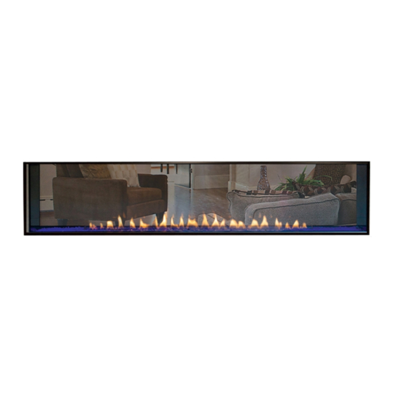
CONTEMPORARY
LINEAR VENT-FREE
GAS FIREPLACE MOdEL
VFLB60SP90(N,P)-1
This appliance may be installed in an aftermarket,
permanently located, manufactured (mobile)
home, where not prohibited by local codes.
This appliance is only for use with the type of gas
indicated on the rating plate. This appliance is not
convertible for use with other gases.
GAS-FIRED
UL FILe No. mh46389
This series is design certified in
accordance with American National
Standard Institute (ANSI) Z21.11.2
by the Canadian Standards
Association Laboratories (CSA)
as an Unvented Room Fireplace
and should be installed according
to these instructions.
Advertisement
Table of Contents

Related Manuals for Boulevard VFLB60SP90-1


Summary of Contents for Boulevard VFLB60SP90-1
- Page 1 INSTALLATION INSTRUCTIONS INSTALLER: CONTEMPORARY Leave this manual with the appliance. LINEAR VENT-FREE CONSUMER: GAS FIREPLACE MOdEL Retain this manual for future reference. VFLB60SP90(N,P)-1 WARNING If the information in this manual is not followed exactly, a fire or explosion may result causing property damage, personal injury or loss of life.
-
Page 2: Table Of Contents
TABLE OF CONTENTS SECTION PAGE Before You Start ............................3 - 4 Carton Contents ............................5 hardware Pack ............................6 Important Soot Prevention Steps ....................... 7 Product Specifications ..........................8 homeowner Reference Information ......................8 Accessories ..............................9 Introduction .............................. 10 Important Safety Information ........................ -
Page 3: Before You Start
BEFORE YOU START UNPACkING THE FIREPLACE Carefully remove the bundle from inside the fireplace. This bundle contains two center glass supports and the burner Remove the six screws securing the plywood top to the deflector glass. Put the bundle in an out of the way place to corner supports. - Page 4 BEFORE YOU START (CONT'd) SAMPLE WARNINGS ANd dEFINITIONS: If the fireplace is installed directly on carpeting, tile or other combustible material other than wood flooring, it must be installed dANGER on a metal or wood panel extending the full width and depth of the fireplace.
-
Page 5: Carton Contents
CARTON CONTENTS Items not shown to scale. VFLB 60SP90 SERIES VFLB 60SP90 SERIES Index Quantity Index Quantity description description Supplied Supplied Fireplace AA Battery* Non-combustible Board - top AAA Battery* Non-combustible Board - Side* hardware Pack* Barrier Screen Assembly AC Adaptor* Burner Glass Wall mounted Control Box* Side Burner Glass*... -
Page 6: Hardware Pack
HARdWARE PACk HARdWARE PACk CONTENTS #4 X PhILLIPS SCReW " #4 X ½” PHILLIPS SCREW #10 X ½” HEX HEAD SCREW #8 X 1" PhILLIPS SCReW #8 X 1½” PHILLIPS SCREW NAILING FLANGE (Not to scale) description Quantity Supplied #4 x 3/8 Phillips Pan head Screw #10 X 1/2 Phillips hex head Screw #8 x 1 Inch Self-Drilling Drywall Screw Nailing Flange... -
Page 7: Important Soot Prevention Steps
IMPORTANT SOOT PREVENTION STEPS IMPORTANT NOTICE INStALLeR - SeRVICe PeRSoN - homeoWNeR SOOT MAY BE CREATEd IF THE FOLLOWING dIRECTIONS ARE NOT FOLLOWEd Ensure the air shutter is set to the specification. See WARNING Figure 3 and Tables 1 and 2 on page 8. Failure to keep the primary air openings of the burner clean Ensure burner, venturi, and air shutter are free of dirt, lint, may result in sooting and property damage. -
Page 8: Product Specifications
PROdUCT SPECIFICATIONS VFLB60SP90P (PROPANE GAS) VFLB60SP90N (NATURAL GAS) Input BtU/hR maximum 38,500 40,000 Input BtU/hR minimum 30,000 27,000 Orifice 1.8mm NOTICE: Air shutter settings are factory set and may not be altered. GAS SUPPLY PRESSURES (inches water column) Gas Type Maximum Minimum Manifold... -
Page 9: Accessories
ACCESSORIES REQUIREd ACCESSORIES ACCESSORIES FOR VFLB60SP90(N,P)-1 PART NUMBER dESCRIPTION VFLB60 DG1CLF Decorative Glass, Crushed - Clear Frost (One kit per one square foot) Recommended DG1BKP Decorative Glass, Crushed - Black Polished (One kit per one square foot) DG1BUC Decorative Glass, Crushed - Blue Clear (One kit per one square foot) DG1BCR Decorative Glass, Crushed - Copper Reflective (One kit per one square foot) DG1BZR... -
Page 10: Introduction
INTROdUCTION INSTRUCTIONS TO INSTALLER The term qualified agency means any individual, firm, corporation or company which either in person or through a representative Leave instruction manual with owner after installation. is engaged in and is responsible for (a) the installation or Have owner register online or fill out and mail the Product replacement of gas piping or (b) the connection, installation, Registration Card supplied with the unvented fireplace. -
Page 11: Important Safety Information
IMPORTANT SAFETY INFORMATION WARNING dANGER When used without adequate combustion and ventilation air, The installer is responsible for the verifying the correct appliance may give off CARBON MONOXIdE, an odorless, position of the air shutter and adjusting it if required. If not poisonous gas. -
Page 12: Safety Information For Users Of Propane Gas
SAFETY INFORMATION FOR USERS OF PROPANE GAS SOME POINTS TO REMEMBER Propane is a flammable gas which can cause fires and explosions. In its natural state, propane is odorless and colorless. • Learn to recognize the odor of Propane Gas. Your local You may not know all the following safety precautions which can Propane Gas Dealer can give you a Scratch and Sniff protect both you and your family from an accident. -
Page 13: Important Installation Guidelines
IMPORTANT INSTALLATION GUIdELINES PROPER PRIMARY AIRFLOW INTO BURNER TELEVISION CONSIdERATIONS For proper burner operation and flame appearance, the flow of Installing a television above a fireplace has become increasingly primary air into the venturi tube, located at the gas inlet of the popular;... -
Page 14: Provisions For Adequate Combustion And Ventilation Air
PROVISIONS FOR AdEQUATE COMBUSTION & VENTILATION AIR This heater shall not be installed in a confined space unless provisions DIVIDER are provided for adequate combustion and ventilation air. The National Fuel Gas Code defines a confined space as a space whose volume is less than 50 cubic feet per 1,000 Btu per hour (4.8m per kw) FIREPLACE... - Page 15 PROVISIONS FOR AdEQUATE COMBUSTION & VENTILATION AIR If the area in which the heater may be operated is smaller than that VENTILATION AIR FROM OUTdOORS defined as an unconfined space, provide adequate combustion and Provide extra fresh air by using ventilation grills or ducts. two ventilation air by one of the following methods: permanent openings must be provided;...
-
Page 16: Fireplace Dimensions (Without Kit)
FIREPLACE dIMENSIONS (WO/kIT) ELECTRICAL ELECTRICAL ACCESS ACCESS GAS LINE GAS LINE ACCESS ACCESS HOLES IN STANDOFF GAS LINE GAS LINE ACCESS ACCESS VFLB60SP INdEX dIMENSION dESCRIPTION dIMENSION LETTER (In Inches) the maximum height of Firebox Face (excluding Standoffs) 22-1/2 the maximum Width of the Firebox Face (excluding Nailing Flanges) 66-3/16 the maximum Depth of the Firebox 11-3/4... -
Page 17: Fireplace Dimensions (With Kit)
FIREPLACE dIMENSIONS (W/kIT) ELECTRICAL ELECTRICAL ACCESS ACCESS GAS LINE GAS LINE ACCESS ACCESS HOLES IN STANDOFF GAS LINE GAS LINE ACCESS ACCESS Outdoor kit - dFEV60LSS VFLB60SP INdEX dIMENSION dESCRIPTION dIMENSION LETTER (In Inches) the maximum height of Firebox Face (excluding Standoffs) 22-1/2 the maximum Width of the Firebox Face (excluding Nailing Flanges) 66-3/16... -
Page 18: Clearances
CLEARANCES WARNING WARNING If installed on an outside wall, order dFEV60LSS. See framing do not put screws through large non-combustible board and clearances for outside wall in instructions. (Option 3) and into the fireplace. Attach screws only in standoffs. MANTEL CLEARANCES FINISHED WALL FINISHED WALL FLAT MANTEL SHELF... -
Page 19: Framing Options
FRAMING OPTIONS REAd THIS BEFORE FRAMING IS BEGUN OPTION 1 allows the non-combustible board to be installed within 1/16 inch of the flange around the fireplace opening. By taping This versatile fireplace can be installed in a variety of ways. Finishing the joints between the non-combustible board and the surrounding Options 1 and 2 are for the fireplace face that opens to an interior wallboard and then expertly finishing the wall with plaster or... - Page 20 FRAMING OPTIONS (CONT'd) OPTION 1 - OPTION 1 OPTION 1 - OPTION 2 OPTION 2 - OPTION 2 OPTION 1 - OPTION 3 OPTION 2 - OPTION 3 Figure 18 - Framing dimensions C Page 20 40217-0-0219...
-
Page 21: Adding Nailing Flanges And Standoff Brackets
AddING NAILING FLANGES ANd STANdOFF BRACkETS At the top and bottom of the fireplace, use pliers to bend 3c. Slide the outer glass and frame over the top and sides of the each side standoff 90 degrees away from the cabinet. See fireplace. - Page 22 AddING NAILING FLANGES ANd STANdOFF BRACkETS 3f. Secure nailing flanges to the side of the fireplace and repeat the brackets have a perforation at the bottom of each side. for the other side. Bend them at the perforation. See Figure 28. Figure 24 - OPTION 1 Figure 28 9a.
- Page 23 AddING NAILING FLANGES ANd STANdOFF BRACkETS 10a. OPTION 1 - Secure standoff brackets with drywall screws to the framed opening above the fireplace as shown in Figure 31. SCREW INTO EACH BRACKET Figure 31 - OPTION 1 10b. OPTION 2 - Secure 6 standoff brackets with drywall screws to the framed opening above the fireplace as shown in Figure 32.
-
Page 24: Utility Installation
UTILITY INSTALLATION Remove barrier screen assembly from fireplace by lifting up TESTING GAS SUPPLY PRESSURE slightly and pulling out. Set aside. Remove the burner cover by NOTICE: the gas controls are equipped with a captured screw- lifting it up and out. Set aside. type pressure test point. - Page 25 UTILITY INSTALLATION (CONT'd) LEFT (VALVE) SIDE OF FIREPLACE FRONT OF FIREPLACE GAS FLEX LINE Figure 35 Shut-off valve must be accessible after installation. A gas valve and ground joint union should be installed in the gas line upstream of the gas control to aid in servicing. the National Fuel Gas Code requires that a drip leg be installed near the gas inlet.
- Page 26 UTILITY INSTALLATION (CONT'd) JUNCTION BOX WIRING INSTALLATION Remove the electrical access cover panel from the left end of the fireplace. See Figure 40. A factory-installed junction box is located at the lower left corner inside the firebox. For 120V electrical requirements install the electrical receptacles into the junction box.
- Page 27 UTILITY INSTALLATION (CONT'd) 12. Install the wall-mounted control box within 6 feet to the left 14. Route the yellow LeD wire harness with gray remote side or 4 feet from the right. See Figure 43. receiver harness through the bushing. mount the controls and connect the wiring.
- Page 28 UTILITY INSTALLATION (CONT'd) WIRING DIAGRAM IGNITOR NOT USED SENSOR PILOT GREEN BLUE ORANGE WHITE REMOTE RECEIVER YELLOW + ON REMOTE - OFF EXTENSION HARNESS BLACK BLACK NOT USED GAS CONTROL VALVE (GND) AC/DC POWER ADAPTOR ELECTRONIC CONTROL MODULE NOT USED the wire terminals shown in Figure 48 are not connected.
-
Page 29: Installation Option 1 - Clean Face
INSTALLATION OPTION 1 - CLEAN FACE NOTICE: the steps on pages 30 and 31 are for installation oPtIoN 1 - Clean Face. This type of installation will allow for finishing around the fireplace face with high-temperature paint. See pages 33 and 34 for installing the fireplace for installation oPtIoN 2 - Flush mount. See page 36 for installing oPtIoN 3 - exterior Decorative Front. -
Page 30: Option 1 - Clean Face (Non - Combustible Board Installation)
OPTION 1 - CLEAN FACE ( NON-COMBUSTIBLE BOARd INSTALLATION ) NOTICE: If installing a decorative front, an offset between the finishing materials and fireplace opening is required. Refer to the CEILING ENCLOSURE installation instructions provided with the decorative front before framing the opening. - Page 31 OPTION 1 - CLEAN FACE ( NON-COMBUSTIBLE BOARd INSTALLATION ) Install non-combustible board provided with the fireplace. See Figure 52. • Do not attach non-combustible board to the fireplace. Attach non-combustible board only to framing and standoffs. • Space non-combustible board 1/16 inch off of fireplace opening flanges to allow for expansion during operation.
-
Page 32: Installation Option 2 - Flush Mount
INSTALLATION OPTION 2 - FLUSH MOUNT NOTICE: The steps on pages 33, and 34 are for installation oPtIoN 2 - Flush mount. This type of installation will allow for applying tile, marble, stone or other non-combustible materials over the face of the fireplace cabinet up to the flange opening. See pages 30 and 31 for installation oPtIoN 1 - Clean Face. -
Page 33: Option 2 - Flush Face (Non - Combustible Board Installation)
OPTION 2 - FLUSH FACE ( NON-COMBUSTIBLE BOARd INSTALLATION ) NOTICE: If installing a decorative front, an offset between the finishing materials and fireplace opening is required. Refer to the CEILING ENCLOSURE installation instructions provided with the decorative front before framing the opening. - Page 34 OPTION 2 - FLUSH FACE (NON-COMBUSTIBLE BOARd INSTALLATION) Install non-combustible board provided with the fireplace. See Figure 56. • Do not attach non-combustible board to the fireplace face. Attach non-combustible board only to the framing and standoffs. • Space non-combustible board 1/16 inch off of fireplace opening flanges to allow for expansion during operation.
-
Page 35: Option 3 - (Finishing Exterior Decorative Front Installation)
OPTION 3 - (FINISHING EXTERIOR dECORATIVE FRONT INSTALLATION) NOTICE: the fireplace must be protected during finishing. Do not 3b. Exterior non-combustible finishing material is placed over the face of the outdoor kit. See Figure 61. allow acid wash to get onto the fireplace. the stainless may be covered in full or in part by a non-combustible stone, tile or other finishing material. -
Page 36: Completing Installation
COMPLETING INSTALLATION Figure 64 WARNING Retrieve the 4 glass panels and install on front, back and Failure to position the parts in accordance with the diagrams both sides of burner. See Figure 65. and instructions below or failure to use only parts specifically approved for use with this fireplace may result in property damage or personal injury. - Page 37 COMPLETING INSTALLATION Apply crushed glass to the shaded area only. See Figure 66. Use enough to cover the area of the fireplace, but do not allow the media to reach higher than the flange surrounding the burner. Never place decorative media inside the flange surrounding the burner itself.
-
Page 38: Lighting Instructions
LIGHTING INSTRUCTIONS FOR YOUR SAFETY REAd BEFORE LIGHTING WARNING If you do not follow these instructions exactly, a fire or explosion may result causing property damage, personal injury or loss of life. A. this appliance has a pilot which can be lit by hand or by C. -
Page 39: Pilot Flame Characteristics
PILOT FLAME CHARACTERISTICS Figure 69 shows a correct pilot flame pattern. The correct flame IGNITOR will be blue and will extend beyond the flame sensor. The flame will surround the flame sensor just below the tip. A slight yellow flame may occur where the pilot flame and main burner flame SENSOR meet. -
Page 40: Proflame - Ip Control System
PROFLAME - IP CONTROL SYSTEM TECHNICAL dATA Remote Control Supply voltage 4.5 V (three 1.5 V AAA batteries) Ambient temperature 0-50°C (32 - 122°F) ratings Radio frequency 315 MHz RECEIVER Supply voltage 6.0 V (four 1.5 V AA batteries) Ambient temperature 0-60°C (32 - 140°F) ratings Figure 72 - transmitter LCD display... -
Page 41: Troubleshooting
TROUBLESHOOTING BRIEF dESCRIPTION OF THE COMPONENTS the Digital Fireplace Control (DFC) is an automatic gas ignition system based on a single micro-controller core. this control manages all functions related to ignition, flame sensing and supervision for atmospheric applications. the DFC can be set to provide continuous or intermittent ignition control sequences and flame monitoring with safety shutdown in case of failure. - Page 42 TROUBLESHOOTING (CONT'd) PROBLEM OBSERVEd POSSIBLE CAUSE CORRECTIVE MEASURE What To do If You Smell Gas Gas odor during setup Gas Leak Do not try to light any appliance. Do not touch any electrical switch; Do not use any phone in your building. Immediately call your gas supplier from a Gas odor before first ignition Gas Leak...
- Page 43 TROUBLESHOOTING (CONT'd) PROBLEM OBSERVEd POSSIBLE CAUSE CORRECTIVE MEASURE Flame sensor dirty Clean pilot sensor Low gas pressure Check gas supply pressure Not enough fresh air for pilot open door or window - ventilate Clogged or dirty burner ports Clean burner ports (For fireplace equipped with optional Move (optional) remote away from fireplace thermostat or thermostat remote) Room...
-
Page 44: Vflb60Sp90 - Exploded View
VFLB60SP90 - EXPLOdEd VIEW BURNER ASSEMBLY WALL PANEL ASSEMBLY LED REPLACEMENT KIT WARNING Failure to position the parts in accordance with these diagrams or failure to use only parts specifically approved with this heater may result in property damage or personal injury. Page 44 40217-0-0219... -
Page 45: Vflb60Sp90 - Parts List
VFLB60SP90 - PARTS LIST PART NO. PART NO. INdEX INdEX dESCRIPTION dESCRIPTION VFLB60SP VFLB60SP 34440 Pilot Bracket 36787 Standoff Bracket (6 Required) R11327 Pilot - Propane 40225 Non-Combustible Board - top (2 Required) Non-Combustible Board - Side (4 R11328 Pilot - Natural 40222 Required) R12666... -
Page 46: Master Parts Distributor List
Please note: master Parts Distributors are independent businesses that stock the most commonly ordered original Equipment repair parts for Heaters, Grills, and Fireplaces manufactured by Empire Comfort Systems Inc. Dey Distributing F. W. Webb Company 1401 Willow Lake Boulevard 200 Locust Street Vadnais Heights, MN 55101 Hartford, CT 06114... -
Page 47: Warranty
WARRANTY Empire Comfort Systems Inc. warranties this hearth product to be free from defects at the time of purchase and for the periods specified below. Hearth products must be installed by a qualified technician and must be maintained and operated safely, in accordance with the instructions in the owner’s manual. - Page 48 Empire Comfort Systems Inc. Belleville, IL If you have a general question about our products, please e-mail us at info@empirecomfort.com. If you have a service or repair question, please contact your dealer. www.empirecomfort.com Page 48 40217-0-0219...
Need help?
Do you have a question about the VFLB60SP90-1 and is the answer not in the manual?
Questions and answers