Table of Contents
Advertisement
Quick Links
INSTALLER:
Leave this manual with the appliance.
CONSUMER:
Retain this manual for future reference.
WARNING
If the information in this manual is not
followed exactly, a fire or explosion may
result causing property damage, personal
injury or loss of life.
— Do not store or use gasoline or other
flammable vapors and liquids in the
vicinity of this or any other appliance.
— WHAT TO DO IF YOU SMELL GAS
•
Do not try to light any appliance.
•
Do not touch any electrical switch; do
not use any phone in your building.
•
Immediately call your gas supplier
from a neighbor's phone. Follow the
gas supplier's instructions.
•
If you cannot reach your gas supplier,
call the fire department.
— Installation and service must be
performed by a qualified installer,
service agency or the gas supplier.
This is an unvented gas-fired heater. It uses air
(oxygen) from the room in which it is installed.
Provisions for adequate combustion and
ventilation air must be provided.
Refer to pages 15.
INSTALLATION INSTRUCTIONS
AND OWNER'S MANUAL
This appliance may be installed in an
aftermarket, permanently located, manufactured
(mobile) home, where not prohibited by local
codes.
This appliance is only for use with the type of
gas indicated on the rating plate. This appliance
is not convertible for use with other gases.
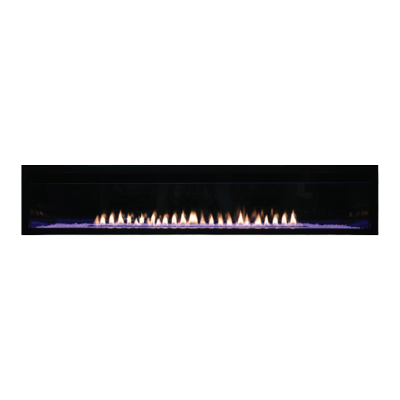
CONTEMPORARY
LINEAR VENT-FREE
GAS FIREPLACE MODELS
VFLL60FP90L(N,P)-1
VFLL72FP90L(N,P)-1
GAS-FIRED
UL FILE NO. MH46389
This series is design
certified in accordance
with American National
Standard Institute (ANSI)
Z21.11.2 by the Canadian
Standards Association
Laboratories (CSA) as
an Unvented Room
Fireplace and should
be installed according to
these instructions.
Page 1
Advertisement
Table of Contents

Subscribe to Our Youtube Channel
Related Manuals for Boulevard VFLL72FP90LN-1


Summary of Contents for Boulevard VFLL72FP90LN-1
- Page 1 INSTALLATION INSTRUCTIONS AND OWNER'S MANUAL INSTALLER: CONTEMPORARY Leave this manual with the appliance. LINEAR VENT-FREE CONSUMER: GAS FIREPLACE MODELS Retain this manual for future reference. VFLL60FP90L(N,P)-1 VFLL72FP90L(N,P)-1 WARNING If the information in this manual is not followed exactly, a fire or explosion may result causing property damage, personal injury or loss of life.
-
Page 2: Table Of Contents
TABLE OF CONTENTS SECTION PAGE Before You Start ................................3 Carton Contents ................................5 Hardware Pack ................................6 Important Soot Prevention Steps ..........................7 Product Specifications ..............................8 Homeowner Reference Information ..........................8 Accessories ................................. 9 Introduction ................................10 Important Information ..............................11 Important Safety Information ............................. -
Page 3: Before You Start
BEFORE YOU START UNPACKING THE FIREPLACE Carefully remove the bundle from inside the fireplace. This Remove the four screws securing the plywood top to the bundle contains two center glass supports and the burner corner supports. Remove the plywood top and discard. deflector glass. - Page 4 BEFORE YOU START SAMPLE WARNINGS AND DEFINITIONS: If the fireplace is installed directly on carpeting, tile or other combustible material other than wood flooring, it must be installed DANGER on a metal or wood panel extending the full width and depth of the fireplace.
-
Page 5: Carton Contents
CARTON CONTENTS CARTON CONTENTS Items not shown to scale. Index Quantity Description Number Supplied Fireplace Non-combustible Board - Top Non-combustible Board - Side Front Glass Burner Glass Bushing Standoff Bracket Receptical Remote AA Battery AAA Battery Hardware Pack AC Adaptor Wall Mounted Control Box Remote Receiver Button Switch... -
Page 6: Hardware Pack
HARDWARE PACK HARDWARE PACK CONTENTS #4 X ½” STAINLESS PHILLIPS HEAD SCREW #10 X ½” HEX HEAD SCREW 1” PHILLIPS SELF-DRILLING SCREW NAILING FLANGES (Not to scale) Quantity Description Supplied 4 x 1/2 Phillips Pan Head Screw 10 X 1/2 Phillips Hex Head Screw #8 x 1 inch Self-Drilling Drywall Screw Nailing Flange See Parts Lists on page 46 - 47 for ordering replacement parts. -
Page 7: Important Soot Prevention Steps
IMPORTANT SOOT PREVENTION STEPS IMPORTANT NOTICE INSTALLER - SERVICE PERSON - HOMEOWNER SOOT MAY BE CREATED IF THE FOLLOWING DIRECTIONS ARE NOT FOLLOWED. A vent-free fireplace or burner draws room air to support Verify the air shutter for the correct setting. Refer to Tables 1 and combustion. -
Page 8: Product Specifications
PRODUCT SPECIFICATIONS VFLL60FP90LP VFLL60FP90LN VFLL72FP90LP VFLL72FP90LN Input BTU/HR Maximum 38,500 40,000 38,500 40,000 Input BTU/HR Minimum 31,000 25,000 31,000 25,000 Orifice 1.8mm 1.8mm Notice: Air shutter settings are factory set and muay not be altered. GAS SUPPLY PRESSURES (inches water column) GAS TYPE MAXIMUM MINIMUM... -
Page 9: Accessories
ACCESSORIES REQUIRED ACCESSORIES Part Number Description VFLL60 VFLL72 DG1CLF DG1CLF Decorative Glass, Crushed - 1/4 inch Clear Frost (One kit per one square foot) Recommended DG1BKP DG1BKP Decorative Glass, Crushed - 1/4 inch Black Polished (One kit per one square foot) DG1BUC DG1BUC Decorative Glass, Crushed - 1/4 inch Blue Clear (One kit per one square foot) -
Page 10: Introduction
INTRODUCTION Installation on Rugs and Tile Instructions to Installer If this fireplace is installed directly on carpeting, tile or other Leave instruction manual with owner after installation. combustible material other than wood flooring the fireplace shall Have owner fill out and mail Product Registration Card be installed on a metal or wood panel extending the full width and supplied with unvented fireplace. -
Page 11: Important Information
IMPORTANT INFORMATION For the Homeowner WARNING • Do not allow Combustible Materials adjacent to or in contact Failure to keep the primary air opening(s) of the burner(s) with the fireplace. Combustible materials include wood, clean may result in sooting and property damage. compressed paper, plant fibers, or other materials that will burn. -
Page 12: Important Safety Information
IMPORTANT SAFETY INFORMATION WARNING DANGER When used without adequate combustion and ventilation air, The installer of this product is responsible for the verifying the appliance may give off CARBON MONOXIDE, an odorless, correct position of the air shutter and adjusting it if required. poisonous gas. -
Page 13: Safety Information For Users Of Lp-Gas
SAFETY INFORMATION FOR USERS OF LP-GAS Propane (LP-Gas) is a flammable gas which can cause fires and Some points to remember explosions. In its natural state, propane is odorless and colorless. • Learn to recognize the odor of LP-Gas. Your local LP-Gas You may not know all the following safety precautions which can Dealer can give you a Scratch and Sniff pamphlet. -
Page 14: Important Installation Guidelines
IMPORTANT INSTALLATION GUIDELINES Proper Primary Airflow into Burner Television Considerations For proper burner operation and flame appearance, the flow of Installing a television above a fireplace has become increasingly primary air into the venturi tube, located at the gas inlet of the popular;... -
Page 15: Provisions For Adequate Combustion & Ventilation Air
PROVISIONS FOR ADEQUATE COMBUSTION & VENTILATION AIR This heater shall not be installed in a confined space unless provisions are provided for adequate combustion and ventilation air. DIVIDER The National Fuel Gas Code defines a confined space as a space whose volume is less than 50 cubic feet per 1,000 Btu per hour (4.8m per kw) FIREPLACE... -
Page 16: Fireplace Dimensions
FIREPLACE DIMENSIONS ELECTRICAL ACCESS GAS LINE ACCESS HOLES IN STANDOFF GAS LINE ACCESS INDEX VFLL60FP VFLL72FP DIMENSION DESCRIPTION LETTER Dimensions in Inches The maximum height of firebox face (excluding standoffs) 22-1/4 22-1/4 The maximum width of the firebox face (excluding nailing flanges) 64-3/4 76-3/4 The maximum depth of the firebox... -
Page 17: Junction Box Wiring Installation
JUNCTION BOX WIRING INSTALLATION Remove the junction box assembly from inside of the All wiring must be done by a qualified electrician and shall be in fireplace. See Figure 10. compliance with all local, city and state building codes. Before making the electrical connection, make sure the main power supply is disconnected. -
Page 18: Gas Supply
GAS SUPPLY The gas pipeline can be brought in through the left side of the NOTICE: The gas controls are equipped with a captured screw- fireplace. The fireplace has a Flexline located on the left side type pressure test point. It is not necessary to provide a 1/8-inch when facing the fireplace. -
Page 19: Clearances
CLEARANCES Mantel Clearances FINISHED WALL FLAT MANTEL SHELF 12” 10” 36” MINIMUM CLEARANCE 8” TO CEILING NON-COMBUSTIBLE BOARD 22 1/2” REQUIRED IN THIS AREA (SUPPLIED WITH FIREPLACE) 6” HEADER 4” 2” STANDOFFS 6” NON-COMBUSTIBLE MINIMUM CLEARANCE MATERIAL (MAY BE TO PERPENDICULAR INSTALLED TO EDGE COMBUSTIBLE OF FIREPLACE OPENING) -
Page 20: Installation Option 1 - Clean Face
INSTALLATION OPTION 1 - CLEAN FACE Attention! The installation steps on pages 21 - 24 are for Installation Option 1 - Clean Face. See pages 26 - 29 for installing the fireplace for Installation Option 2 - Flush Mount. This type of installation will allow for finishing around the fireplace face with high temperature paint. Page 20 36776-6-0618... -
Page 21: Framing - Clean Face
FIREPLACE & NONCOMBUSTIBLE BOARD FRAMING - CLEAN FACE INSTALLATION - CLEAN FACE Frame in rough opening. • This fireplace is designed to be mounted on a hard, flat surface or raised platform. • Use dimensions shown in Figure 19 for a conventional rough opening. -
Page 22: Nailing Flanges & Mounting Brackets - Clean Face
NAILING FLANGES & STANDOFF BRACKETS - CLEAN FACE NOTICE: You must use the nailing flanges and standoff brackets Locate nailing flanges in the envelope pack. The holes in the that are supplied with the fireplace. The brackets are shipped nailing flanges allow for different size boards and locations inside the hardware box behind the fireplace. -
Page 23: Fireplace & Noncombustible Board Installation - Clean Face
FIREPLACE & NONCOMBUSTIBLE BOARD INSTALLATION - CLEAN FACE Insert fireplace into enclosure. Level fireplace. Secure three standoff brackets with drywall screws to the framed opening above the fireplace as shown in Figure 28. NOTICE: The drywall screws are located in the instruction envelope packet. - Page 24 FIREPLACE & NONCOMBUSTIBLE BOARD INSTALLATION - CLEAN FACE 11. Place batteries in receiver boxes and remotes using FINISHED PAINTED WALL instructions provided. Verify remote is communicating with receiver. NON-COMBUSTIBLE FRAMING BOARD INSTALLED Important! If installing a decorative front, an offset between the HEADER OVER FIREPLACE FACE finishing materials and fireplace opening is required.
-
Page 25: Installation Option 2 - Flush Mount
INSTALLATION OPTION 2 - FLUSH MOUNT Attention! The installation steps on pages 26 - 29 are for Installation Option 2 - Flush Mount. See pages 21 - 24 for installing the fireplace for Installation Option 1 - Clean Face. This type of installation will allow you to apply tile, marble, stone or other non-combustible material over the face of the fireplace cabinet, up to the flange opening. -
Page 26: Framing - Flush Mount
FRAMING - FLUSH MOUNT Frame in rough opening. • This fireplace is designed to be mounted on a hard, flat surface or raised platform. Use dimensions shown in Figure 34 for a conventional • rough opening. • Use Figure 35 for an elevated installation. Provide support to the bottom of the fireplace. -
Page 27: Nailing Flanges & Mounting Brackets - Flush Mount
NAILING FLANGES & STANDOFF BRACKETS - FLUSH MOUNT NOTICE: You must use the nailing flanges and mounting On the top and bottom of each side are side framing brackets that are supplied with the fireplace. The brackets are standoffs. Use pliers to bend the side framing standoff 90 degrees away from the cabinet. -
Page 28: Fireplace & Noncombustible Board Installation - Flush Mount
FIREPLACE & NONCOMBUSTIBLE BOARD INSTALLATION - FLUSH MOUNT Insert fireplace into enclosure. Level fireplace. Secure three middle mounting brackets with drywall screws to the framed opening above the fireplace as shown in Figure 43. NOTICE: The drywall screws are located in the instruction envelope packet. - Page 29 FIREPLACE & NONCOMBUSTIBLE BOARD INSTALLATION - FLUSH MOUNT 11. Place batteries in receiver boxes and remotes using FINISHED WALL instructions provided. Verify remote is communicating with NON-COMBUSTIBLE FRAMING TILE OR OTHER receiver. HEADER MATERIAL NON-COMBUSTIBLE BOARD INSTALLED Important! If installing a decorative front, an offset between the ON TOP OF FIREPLACE finishing materials and fireplace opening is required.
-
Page 30: Completing Installation - Clean Face & Flush Mount
COMPLETING INSTALLATION - CLEAN FACE & FLUSH MOUNT Replace LED reflector. Install optional decorative surround panel assembly. Retrieve shorter glass and install in front of burner. Refer to instructions included with the surround panel kit. If installing an optional liner, install them now. Refer to the If installing an optional inner top deflector, loosen the five instructions provided with the liner kit. -
Page 31: Fireplace Wiring
FIREPLACE WIRING WIRING DIAGRAM IGNITOR SENSOR CPI/IPI PILOT SWITCH GREEN BLUE BLUE ORANGE WHITE WHITE REMOTE RECEIVER YELLOW + ON REMOTE - OFF EXTENSION HARNESS BLACK BLACK NOT USED GAS CONTROL VALVE (GND) AC/DC POWER ADAPTOR ELECTRONIC CONTROL MODULE NOT USED The wire terminals shown in Figure 52 are not connected. -
Page 32: Led Wiring
LED WIRING LED STRIP LED STRIP LED STRIP JUNCTION BOX TRANSFORMER BLACK LEFT BUTTON BRIGHTNESS BLACK BLACK BLACK RIGHT BUTTON BLACK BLACK MODE BLACK YELLOW Figure 53 Page 32 36776-6-0618... -
Page 33: Decorative Glass Installation
DECORATIVE GLASS INSTALLATION WARNING Apply the crushed glass to the shaded area only. See Figure 54. Use enough to cover the floor of the fireplace, but do not Failure to position the parts in accordance with the allow the media to reach higher than the flange surrounding diagrams and instructions below or failure to use only parts the burner. - Page 34 DECORATIVE GLASS INSTALLATION Replace the glass front into the fireplace by placing the right side into the slots in the firebox. Carefully angle in the left side of the glass and then slide the glass to the left. Settle the glass into the slots by gently lowering it. See Figures 55 - 58.
-
Page 35: Lighting Instructions
LIGHTING INSTRUCTIONS FOR YOUR SAFETY READ BEFORE LIGHTING WARNING If you do not follow these instructions exactly, a fire or explosion may result causing property damage, personal injury or loss of life. A. This appliance has a pilot which must be lighted by hand. C. -
Page 36: Pilot Flame Characteristics
PILOT FLAME CHARACTERISTICS Figure 59 shows a correct pilot flame pattern. The correct flame will be blue and will extend beyond the flame sensor. The flame will surround the flame sensor just below the tip. A slight yellow flame may occur where the pilot flame and main burner flame meet. -
Page 37: Proflame - Ip Control System
PROFLAME - IP CONTROL SYSTEM TECHNICAL DATA Remote Control Supply voltage 4.5 V (three 1.5 V AAA batteries) Ambient temperature 0-50°C (32 - 122°F) ratings Radio frequency 315 MHz Receiver Supply voltage 6.0 V (four 1.5 V AA batteries) Ambient temperature 0-60°C (32 - 140°F) ratings Figure 61 - Transmitter LCD display... -
Page 38: Operating Instructions
OPERATING INSTRUCTIONS 5.25 VDC ELECTRONIC CONTROL VALVE When the fireplace is turned to ON, the electrical current will energize a spark to the pilot igniter. Once the pilot sensor heats The electronic control valve system includes the ability to switch up (after a few seconds), the valve will be energized, allowing the pilot from a standing pilot mode to an intermittent pilot mode. -
Page 39: Cleaning And Service
CLEANING AND SERVICE Annual inspection and cleaning by your dealer or qualified If intermittent pilot fireplace stops working, clean flame service technician is recommended to prevent malfunction and/ sensor B (Figure 65) with a damp cloth. or sooting. If intermittent pilot ignitor does not spark, clean ignitor C TURN OFF FIREPLACE AND ALLOW TO COOL BEFORE (Figure 65) with a damp cloth. -
Page 40: Testing The Gas Supply Pressure
TESTING THE GAS SUPPLY PRESSURE Natural gas will have a manifold pressure of approximately 3.5 inches w.c. at the pressure regulator outlet with the inlet pressure to the pressure regulator from a minimum of 7.0 inches w.c. for the purpose of input adjustment to a maximum of 10.5 inches w.c. -
Page 41: Troubleshooting
TROUBLESHOOTING Brief Description of the Components The Digital Fireplace Control (DFC) is an automatic gas ignition system based on a single micro-controller core. This control manages all functions related to ignition, flame sensing and supervision for atmospheric applications. The DFC can be set to provide continuous or intermittent ignition control sequences and flame monitoring with safety shutdown in case of failure. - Page 42 TROUBLESHOOTING (CONT'D) PROBLEM OBSERVED POSSIBLE CAUSE CORRECTIVE MEASURE What To Do If You Smell Gas Gas odor during setup Gas Leak Do not try to light any appliance. Do not touch any electrical switch; Do not use any phone in your building. Immediately call your gas supplier from a Gas odor before first ignition Gas Leak...
- Page 43 TROUBLESHOOTING (CONT'D) PROBLEM OBSERVED POSSIBLE CAUSE CORRECTIVE MEASURE Flame sensor dirty Clean pilot sensor Low gas pressure Check gas supply pressure Not enough fresh air for pilot Open door or window - ventilate Clogged or dirty burner ports Clean burner ports (For fireplace equipped with optional Move (optional) remote away from fireplace Burner &...
-
Page 44: Exploded View
EXPLODED VIEW BURNER ASSEMBLY WALL PANEL ASSEMBLY WARNING Failure to position the parts in accordance with these diagrams or failure to use only parts specifically approved with this heater may result in property damage or personal injury. Page 44 36776-6-0618... -
Page 45: Parts List
PARTS LIST PART NUMBER PART NUMBER INDEX INDEX DESCRIPTION DESCRIPTION VFLL60FP VFLL72FP VFLL60FP VFLL72FP Standoff Bracket Pilot - Regulator Tube 36787 36787 36770 36770 (3 Required) Assembly (NAT Only) Non-Combustible Board Valve - Regulator Tube 36774 36804 36769 36769 Assembly (NAT Only) - Top Non-Combustible Board - Regulator - Pilot (NAT... -
Page 46: Master Parts Distributor List
Please note: Master Parts Distributors are independent businesses that stock the most commonly ordered Original Equipment repair parts for Heaters, Grills, and Fireplaces manufactured by Empire Comfort Systems Inc. Dey Distributing F. W. Webb Company 1401 Willow Lake Boulevard 200 Locust Street Vadnais Heights, MN 55101 Hartford, CT 06114... -
Page 47: For The Homeowner
FOR THE HOMEOWNER Empire Comfort Systems has manufactured safe, CONTEMPORARY LINEAR reliable heating systems since 1932. We take pride in our VENT-FREE GAS FIREPLACE reputation for quality products, backed by the best sales, service and distribution network in this industry. These MODELS fireplace models combine our proven technologies with VFLL60FP90L(N,P)-1... -
Page 48: Important Information
IMPORTANT INFORMATION Maintenance and Service WARNING Although the frequency of servicing and maintenance will depend on use and the type of installation, you should have a qualified Read and follow these safety precautions prior to operat- service technician perform an appliance checkup at the beginning ing this appliance. -
Page 49: Removing & Replacing The Glass Front
REMOVING & REPLACE THE GLASS FRONT Removing the Glass Front Replacing the Glass Front Lift the glass front up, slide it to the right, and then carefully Place the right side of the glass into the slots in the firebox. angle left side out of the slots. -
Page 50: Decorative Glass & Rock Placement
DECORATIVE GLASS & ROCK PLACEMENT The Decorative Glass options are available in various colors and package sizes. Choose the size appropriate for your fireplace. See list on page 9. CAUTION Crushed glass and Glass droplets must not be more than a single layer. -
Page 51: Lighting Instructions
LIGHTING INSTRUCTIONS FOR YOUR SAFETY READ BEFORE LIGHTING WARNING If you do not follow these instructions exactly, a fire or explosion may result causing property damage, personal injury or loss of life. A. This appliance has a pilot which must be lighted by hand. C. -
Page 52: Operating Instructions
LED & FIREPLACE WALL CONTROLS LED Brightness Button BATTERY REPLACEMENT Press the LED Brightness Button to activate the LED lights and To replace the batteries in an intermittent unit, follow these steps: to cycle LED Intensity from High to Low to Off. Remove the cover from the electrical box on the wall. -
Page 53: Using The Remote Control
USING THE REMOTE CONTROL Transmitter (Remote Control with LCD Display) CAUTION The Proflame Transmitter uses a streamline design with a simple button layout and informative LCD display (Figure H). The transmitter and receiver are radio frequency devices. The Transmitter is powered by 3 AAA type batteries. A Mode Placing the receiver in or near metal may severely reduce the Button is provided to Index between the features and a signal range. - Page 54 USING THE REMOTE CONTROL Initializing the System Turn On the Fireplace Install the 4 AA batteries into the receiver battery bay. Note the Press the ON/OFF Button on the Transmitter. The Transmitter polarity of battery and insert into the battery bay as indicated on display will show all active Icons on the screen.
- Page 55 USING THE REMOTE CONTROL Remote Flame Control The Proflame GTM has six flame levels. With the system on, and the flame level at the maximum in the fireplace, pressing the Down Arrow Button once will reduce the flame height by one step until the flame is turned off.
- Page 56 USING THE REMOTE CONTROL Thermostat Operation Smart Thermostat (Transmitter Operation) The Remote Control can operate as a room thermostat. The The Smart Thermostat function adjusts the flame height in thermostat can be set to a desired temperature to control the accordance to the difference between the set point temperature comfort level in a room.
- Page 57 USING THE REMOTE CONTROL Button Lock Receiver This function will lock the buttons to avoid unsupervised The life span of the Receiver batteries depends on various operation. factors: quality of the batteries used, the number of ignitions of To activate this function, press the MODE and the UP Arrow the fireplace, the number of changes to the room thermostat set Button at the same time (Figure U).
-
Page 58: Warranty
A bill of sale, cancelled check, or payment record in the owner’s manual. Empire will not warranty any should be kept to verify purchase date and establish Boulevard fireplace that is not installed by the selling warranty period. dealer or that dealer’s direct contract agents. - Page 59 This page intentionally left blank. 36776-6-0618 Page 59...
- Page 60 Empire Comfort Systems Inc. Belleville, IL If you have a general question about our products, please e-mail us at info@empirecomfort.com. If you have a service or repair question, please contact your dealer. www.empirecomfort.com Page 60 36776-6-0618...
Need help?
Do you have a question about the VFLL72FP90LN-1 and is the answer not in the manual?
Questions and answers