Table of Contents
Advertisement
Quick Links
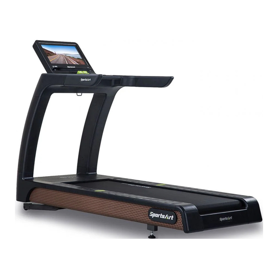
T676-16"&19" SENZA CONSOLE OWNER'S MANUAL
SENZA SERIES DISCLAIMER TERMS ................................................. 1
1. INTRODUCTION ................................................................................ 2
2. SAFETY PRECAUTIONS ..................................................................
3. LIST OF PARTS .................................................................................
4. ASSEMBLE THE PRODUCT ............................................................. 10
STEP 0 Preparation: Inspect Walk Belt Placement ............................... 10
STEP 1 Install the Left and Right Pedestals .......................................... 11
STEP 2 Install the Display ..................................................................... 14
STEP 3 Install the Left and Right Side Covers ...................................... 17
STEP 4 Move the Treadmill into Place for Use ..................................... 18
STEP 5 Level the Treadmill ................................................................... 19
STEP 6 Align the Walk Belt ................................................................... 20
STEP 7 Adjust the Walk Belt Tension .................................................... 21
STEP 8 TV Terminal and Network ......................................................... 22
STEP 9 Install the Power Cord ............................................................
5. UNDERSTAND THE T676 16"&19" SENZA CONSOLE ................... 24
DISPLAY Overview ............................................................................... 24
DISPLAY Keys ...................................................................................... 24
DISPLAY Safety Mechanism ................................................................ 25
DISPLAY Windows ................................................................................ 27
6. OPERATE THE PRODUCT ............................................................... 28
OPERATION Safety Operating Area ..................................................... 28
OPERATION Proper Workout Position and Safety Get Off ................... 29
OPERATION Overview .......................................................................... 30
OPERATION Start Screen .................................................................... 30
OPERATION Start your (GO) workout .................................................. 31
OPERATION Workout Selection ............................................................ 32
OPERATION Workout Programs ........................................................... 33
OPERATION Workout Status ................................................................ 34
OPERATION Select Entertainment ....................................................... 36
OPERATION View Entertainment ......................................................... 36
OPERATION Workout Summary ........................................................... 37
OPERATION SA WELL+ ....................................................................... 38
OPERATION Idle Mode ........................................................................ 39
OPERATION Energy Smart Function ................................................... 39
OPERATION Precautions ..................................................................... 39
7. ABOUT HEART RATE DETECTION .................................................. 40
HEART RATE Telemetry ........................................................................ 40
HEART RATE Contact ........................................................................... 40
8. GUIDELINES FOR EXERCISE ......................................................... 41
9. MAINTENANCE ................................................................................ 42
MAINTENANCE Safety Precautions ..................................................... 42
MAINTENANCE Error Messages .......................................................... 43
MAINTENANCE Circuit Breaker ........................................................... 44
MAINTENANCE Lubrication System .................................................... 45
MAINTENANCE Schedule .................................................................... 48
MAINTENANCE Task List ..................................................................... 49
MAINTENANCE One-Year Maintenance Log ....................................... 50
3
8
23
Advertisement
Table of Contents

Related Manuals for SportsArt Fitness T676


Summary of Contents for SportsArt Fitness T676
-
Page 1: Table Of Contents
STEP 7 Adjust the Walk Belt Tension ............ 21 STEP 8 TV Terminal and Network ............22 STEP 9 Install the Power Cord ............5. UNDERSTAND THE T676 16”&19” SENZA CONSOLE ....24 DISPLAY Overview ................24 DISPLAY Keys ..................24 DISPLAY Safety Mechanism .............. - Page 2 T676-16”&19” SENZA CONSOLE OWNER’S MANUAL 10. ACCESSORIES ................ACCESSORIES Entertainment Cap ............ ACCESSORIES MYE Wireless TV Audio_Channel Receivers .... 53 ACCESSORIES Options ..............11. APPENDIXES ................. 55 APPENDIXES Specifications ............... APPENDIXES Electronics Block Diagram ........... APPENDIXES Exploded Diagrams............57 *We reserve the right to revise this manual at any time without notice.
-
Page 3: Senza Series Disclaimer Terms
SENZA SERIES DISCLAIMER TERMS Internet function: A1. This machine provides only a web page browsing method for web page and video browsing. A2. For web page videos, we support only Youku and YouTube. Note: Some videos may not be viewed due to restrictions resulting from country policies, internal server firewalls, or video formats, etc. -
Page 4: Introduction
1. INTRODUCTION Congratulations on the purchase of a high quality SportsArt product, the T676 16” & 19” Senza Console Treadmill. Constructed of high quality materials and designed for years of reliable performance, this product was made for full commercial use. -
Page 5: Safety Precautions
2. SAFETY PRECAUTIONS This product was designed and built for optimum safety. However certain precau- tions apply during the use of this product. Please note the following safety precautions: • Read instruction manual before using. • Make sure the product is installed and operated as instructed in this manual. - Page 6 2. SAFETY PRECAUTIONS (CONTINUED) CAUTION: If you feel any pain or any abnormal sensations, STOP YOUR WORKOUT and consult your physician immediately. Work within your recommended exercise level. DO NOT work to exhaustion. Before beginning any exercise program, you should consult with your doctor. It is recommended that you undergo a complete physical examination.
- Page 7 2. SAFETY PRECAUTIONS (CONTINUED) If you are a French speaking person in North America, please place the following label contained in the owner’s manual on the console as shown. Customers outside of North America will not receive this French warning label.
- Page 8 2. CONSIGNES DE SÉCURITÉ IMPORTANTES Votre tapis de course SportsArt a été conçu et fabriqué afin d’assurer une sécurité optimale. Cependant certaines précautions s’appliquent chaque fois que vous uti- lisez votre tapis de course. • Lisez entièrement le manuel avant l’assemblage et l’utilisation. Veuillez aussi noter les consignes de sécurité...
- Page 9 2. CONSIGNES DE SÉCURITÉ (SUITE) • Pour éviter de vous blesser, restez sur les bandes de repos (barres latérales) avant de démarrer le tapis de course. • Ce tapis de course n’est pas destiné à être utilisé par des personnes (y com- pris des enfants) dont les capacités physiques, sensorielles ou mentales sont réduites ou qui ne disposent pas de l’expérience ou du savoir nécessaires, sauf si celles-ci ont au préalable été...
-
Page 10: List Of Parts
3. LIST OF PARTS Assembly Parts Name Qty. No. Name Qty. A1 Display A5 Main frame A2 Handlebar assembly A6 Hardware kit A3 Right pedestal A7 Owner’s manual A3a Feeder cord A8 Power cord A4 Left pedestal... - Page 11 3. LIST OF PARTS (CONTINUED) Components in the Hardware Kit Name Qty. Specification Notes Double open-end wrench 22mm*24mm Screwdriver shank Plastic fastener T-shaped Allen wrench M6*L260 T-shaped Allen wrench Components on the Product Name Specification Notes Flat washer D22*d8.5*t3.0 QTY 6 Spring washer QTY 6 Inner hex screw...
-
Page 12: Assemble The Product
4. ASSEMBLE THE PRODUCT Follow instructions below to assemble this product. Note that in this manual the words “left” and “right” are used to refer to the product and its parts. As such, these designations correspond to the “left” and “right” sides of a person in position to exercise on this product. -
Page 13: Step 1 Install The Left And Right Pedestals
STEP 1 Install the Left and Right Pedestals Remove the left and right side covers from the main frame and then remove screws (41) from the left and right sides of the main frame (A5). (Note: DO NOT remove screws in area (a).) - Page 14 STEP 1 Install the Left and Right Pedestals (Continued) Follow steps (a) through (e) to thread the data cable into right pedestal (A3). (a) Pull out the data cable from the right pedestal base. Cut the zip tie, and uncurl the data cable. (b) Place the right pedestal (A3) on the floor as shown, with the bottom end facing the data cable.
- Page 15 STEP 1 Install the Left and Right Pedestals (Continued) Follow steps (a) through (b) to install the left and right pedestals (A3) (A4). (a) Attach left and right pedestals (A3) (A4) to the main frame (A5), and use screws (41) to secure the assembly. (Note: Make sure the data cable is not pinched when installing the left and right pedestals (A3) (A4).) (b) Remove screws (42) from left and right pedestals (A3) (A4).
-
Page 16: Step 2 Install The Display
STEP 2 Install the Display Follow steps (a) through (j) to install the display panel. (a) Remove the left and right covers from the handlebar assembly (A2). (b) Attach the handlebar assembly (A2) to the left and right pedestals (A3) (A4), then mount screws (42) in position. - Page 17 STEP 2 Install the Display (Continued) (d) Remove screws (43) from the handlebar assembly (A2). (e) Remove the rear cover of the display (A1). (f) Insert the display into the 2 mounting brackets on the handlebar assembly (A2). Gently press down on the display during installation to avoid the front edge of display protrudes over the storage tray.
- Page 18 STEP 2 Install the Display (Continued) Hold the display (A1) forward slightly as shown and then press downward when securing screws (43). Pull the cables out of the handlebar (A2) and then connect to the cables from the display (A1). After connecting the cables, push the black cover to cover the end of the cables as shown.
-
Page 19: Step 3 Install The Left And Right Side Covers
STEP 3 Install the Left and Right Side Covers Follow steps (a) through (b) to install left and right side covers. (a) Install the plastic fasteners (50) to the left/right pedestals from top to bottom. (There are a total of two places.) (b) Finally, click the left/right side covers of the main frame (A5) and handlebar assembly (A2) into place. -
Page 20: Step 4 Move The Treadmill Into Place For Use
STEP 4 Move the Treadmill Into Place For Use First, place hands under the frame in area A, lift the treadmill and then roll it into position as desired. Note: Do not place the treadmill on thick carpet or rugs as it may interfere with the walking belt. -
Page 21: Step 5 Level The Treadmill
STEP 5 Level the Treadmill Press downward on the rear part of the treadmill as shown. Inspect whether the treadmill rests flat on the floor. If the treadmill wobbles, adjust treadmill levelers as follows: (a) Loosen the leveler nut. (b) Rotate the leveler foot downward, touching the floor. (c) Rotate the leveler nut upward, against the frame of the product, to secure this position. -
Page 22: Step 6 Align The Walk Belt
STEP 6 Align the Walk Belt (a) First, make sure the treadmill is on a leveled surface and the incline is at (b) Start the speed at a lower rate of 3kph/2.5mph to check if the walk belt is aligned and there is an equal amount of space between walk belt and side-rails on both sides. -
Page 23: Step 7 Adjust The Walk Belt Tension
STEP 7 Adjust the Walk Belt Tension As you exercise, does the walk belt suddenly pause and then regain trac- tion? Or, if you bear down against the walk belt, does the belt not pause whatsoever? If either of these two conditions occurs, the walk belt may be too loose or too tight. -
Page 24: Step 8 Tv Terminal And Network
STEP 8 TV Terminal and Network (a) NETWORK: Connect to Ethernet. (b) AV Terminal: Connect to DVD Player or Media Player. (c) The equipment supports MYE Wireless TV Audio_Channel Receivers and is fully compatible with CSAFE protocols (d) TV: Convert any PAL/NTSC signal from any AV source to selectable output of PAL or NTSC. -
Page 25: Step 9 Install The Power Cord
STEP 9 Install the Power Cord (a) First remove screws (45) from the power cord socket on the product. (b) Insert the power cord into place on the product as shown. (c) Secure the power cord with screws (45) and then insert the other end of the power cord (A8) into the appropriate power supply socket in the wall. -
Page 26: Understand The T676 16"&19" Senza Console
5. UNDERSTAND THE SENZA CONSOLE DISPLAY Overview T676 Series 16”&19” Senza Console are designed to help users obtain their fitness goals in a simple and convenient way. Before using the treadmill, please familiarize yourself with the functions of this display console to obtain optimum benefits and enjoyment from this product. -
Page 27: Display Safety Mechanism
DISPLAY Keys No. Name of button Function Insert safety key to allow treadmill to Safety key start. If key is removed, the treadmill will stop immediately. When the machine is in the Energy Smart Energy Smart conservation mode, pressing this button will Wake- wake up the machine and turn the power on Up Button... - Page 28 DISPLAY Safety Mechanism (Continued) (a) Emergency stop key To stop the unit suddenly, press the red emergency stop key downward as shown in the figure (a). To deactivate the safety mechanism, press and hold this key for 3 seconds will reset to the start screen. (b) Safety key The safety mechanism is activated immediately by removing the safety key from the groove as shown in the figure (b).
-
Page 29: Display Windows
DISPLAY Windows Information Specifications SPEED 0.15-17.0 MPH or 0.25-27.0 KPH (international) 0.15-14.0 MPH or 0.25-23.0 KPH (Japan) The machine will start at the system default set- ting speed of 0.5 MPH / 0.8 KPH. INCLINE -3%-15%, in increments of 0.5% TIME 0:00 - 600:00 DISTANCE... -
Page 30: Operate The Product
6. OPERATE THE PRODUCT OPERATION Safety Operating Area (a) Safety clearance required as shown below. Do not allow people to be near this area when operating. (b) The central handlebar at area D is used for heart rate detection only, not for support and to maintain balance. -
Page 31: Operation Proper Workout Position And Safety Get Off
OPERATION Proper Workout Position and Safety Get Off (a) Place your feet on the landing strips and then hold the handles to steady self while stepping into the running belt as shown below. (b) Turn off the treadmill and wait until the running belt comes to a complete stop and then hold onto handles for stability while carefully stepping off the treadmill. -
Page 32: Operation Overview
OPERATION Overview Touch screen design is simple and clear. The screen layout helps users fo- cus on exercise. It provides many workout modes that can help you achieve your fitness goal. The following sections introduce information concerning touch screen operation, the available types of workout, and how to start the workouts. -
Page 33: Operation Start Your (Go) Workout
OPERATION Startup Screen (Continued) No. Name of button Function CUSTOMIZED Web page status display for browsing and opera- WEB PAGE tion WINDOW Touch this button to access workout program se- SELECT lection Displays various virtual realities. Touch this screen FEATURE to access the virtual reality training mode 10 GO Touch this button to start workout... -
Page 34: Operation Workout Selection
OPERATION Start your (GO) workout (Continued) OPERATION Workout Selection Touch the “SELECT” button on the start screen to access “SELECT WORKOUT”. Operation method: Slide finger on screen to move the selection list. Various workout programs are available for selection, from left to right these are QUICK START, LIFESTYLE, INTERVAL TRAINING, SENZA JOURNEYS, 5K TRAINING MODE, GLUTE WORKOUT, HILL WORKOUT, HEART RATE TEST, FITNESS TEST. -
Page 35: Operation Workout Programs
OPERATION Workout Selection (Continued) Description of icons on the “Select” screen ICON Description Tap to return startup screen. During exercising, tap it to stop or resume workout. Pause Quick Tools OPERATION Workout Programs Workout program details are explained below. QUICK START A workout mode option based on time, distance and calories that allows user to start a workout immediately. -
Page 36: Operation Workout Status
OPERATION Workout Programs (Continued) FITNESS TEST A variety of professional fitness test modes are provided, including the fol- lowing programs: • BRUCE heart test uses a modified BRUCE protocol with an electrocar- diogram. • Canada Firefighters Fitness Test Program (GERKIN) •... - Page 37 OPERATION Workout Status (Continued) Drop down menu introduction: Drop Down Menu Items Symbol Default Other Options Average Incline Incline Elevation Gain Change Incline Pace Speed Average Speed Change Speed Time Elapsed Time Remaining (Time will appear as “0:00, Clock where 0 represents minute and Segment Duration 00 represents second.) Target Duration...
-
Page 38: Operation Select Entertainment
OPERATION Select Entertainment You can select the “Select Entertainment” page below the screen, and the available multimedia features will be displayed. The features include TV, In- ternet, SENZA Journeys, Bluetooth Audio, USB Audio USB Video, IPTV and AVIN, etc.: the small central window will display the selected multimedia screen immediately. -
Page 39: Operation Workout Summary
OPERATION View Entertainment (Continued) Description of Icons in the “Entertainment” screen Icon Description Full Screen (To exit full-screen mode, tap anywhere on the screen.) Mute Lower volume Raise volume Slow reverse Play Fast Forward OPERATION Workout Summary At the end of a workout or when you press the stop button, the workout sum- mary screen will appear. -
Page 40: Operation Sa Well
OPERATION SA WELL+ Tap SA WELL+ to enter SA WELL+ Login page. First time user must create an user account with SA WELL+ App. After sign up, user information will be saved into the account. Login to your SA Well+ account to track your workouts and will also allow you to download a created custom workout to machine. -
Page 41: Operation Idle Mode
OPERATION Idle Mode When the treadmill stops running with no other activity for 2 minutes, the ma- chine will enter the idle mode and the display will randomly show the standby picture. Touch any position in the idle mode to enter the Home page. Note: The standby picture can be changed and set by the user. -
Page 42: About Heart Rate Detection
7. ABOUT HEART RATE DETECTION Heart rate detection functions are selected at the time of purchase. Not every product has every type of heart rate detection. The following explains factors that influence the performance of two of the most common types of heart rate detection devices. -
Page 43: Guidelines For Exercise
8. GUIDELINES FOR EXERCISE HOW HARD SHOULD I EXERCISE? Studies show that to benefit from aerobic exercise, people need to maintain a certain heart rate during their workouts. Your heart rate training zone depends on your age and fitness level. The darkened area in the chart to the right represents the recommended heart rate training zone for people of various ages. -
Page 44: Maintenance
9. MAINTENANCE This section covers maintenance topics, including instructions on replacing a fuse and lubricating the walk belt, along with the presentation of a main- tenance schedule, maintenance task list, one-year maintenance log, and electronics block diagram. MAINTENANCE Safety Precautions ●... -
Page 45: Maintenance Error Messages
MAINTENANCE Error Messages When abnormalities occur to the machine, the workout message information window will display “ERROR_X_Y”. X represents the following code definitions: Code Explanation of code category Servo motor abnormality IGBT abnormality Incline motor abnormality Power switch abnormality Communication abnormality Y represents the sub-abnormality under the X abnormality code Error code explanations follow: ERROR_1_1_ : Servo motor encoder abnormality. -
Page 46: Maintenance Circuit Breaker
MAINTENANCE Circuit Breaker (a) A circuit breaker is an automatically operated electrical switch designed to protect an electrical circuit from damage caused by overcurrent/ overload or short circuit. A spring located under the push button causes the button at area D to lift up and the breaker to trip as shown in the figure (a). -
Page 47: Maintenance Lubrication System
MAINTENANCE Lubrication System Lubrication System Flowchart Lubricant Change Procedure Note: Pay extra attention during the lubricant changing procedure to avoid electric shock; especially operating it while the power is on. - Page 48 MAINTENANCE Lubrication System (Continued) To replace the lubricant bottle, follow instructions (a) through (d) below. (a) Loosen the screws on the bezel and push the bezel up. (b) Take the old lubricant bottle out. (c) Unscrew the nozzle from the old lubricant bottle and screw it onto new bottle.
- Page 49 MAINTENANCE Lubrication System (Continued) Error Messages: There are 2 error messages with this system. Error 1: It indicates that the system memory failing and it will not be able to perform any auto lubrication. Error 2: It indicates motor is failing or system will not be able to perform any function.
-
Page 50: Maintenance Schedule
MAINTENANCE Schedule Area Day Week Month Quarter Year Notes Exterior Clean. Screws Inspect and secure loose parts. Ensure the treadmill operates properly. Treadmill test Inspect alignment (centering) and look Walk belt for wear. Walk deck Inspect for wear. Belt guides Inspect for normal rotation. -
Page 51: Maintenance Task List
MAINTENANCE Task List Like cars, fitness products require maintenance. Regular maintenance ex- tends product life, and failure to maintain products can void the manufac- turer’s warranty. Copy the maintenance log sheet, and record maintenance work for each fitness product. Daily tasks 1. -
Page 52: Maintenance One-Year Maintenance Log
MAINTENANCE One-Year Maintenance Log Facility:_______________________ Supervisor:____________________ Product model number:__________ Serial number:_________________ Start date: ____________________ End date:_____________________ Daily Tasks Weeks 1-7 Weeks 8-14 Weeks 15-21 Week 22-28 Completed Daily Tasks Week 29-35 Week 36-42 Week 43-49 Week 50-52 Completed Weekly Tasks Weeks 1-7 Weeks 8-14 Weeks 15-21 Weeks 22-28... -
Page 53: Accessories
10. ACCESSORIES These accessories are related to the functions of this machine. Some are standard and others are optional. The details of each accessory and its function are explained. USB CHARGER (Standard) The USB charger will provide 5V and 1.5A voltage for charging of smart phone or other devices. -
Page 54: Accessories Entertainment Cap
ACCESSORIES Entertainment Cap Item Name Function USB port This port is used for data transferring. When a smart phone is connected with equipment, Bluetooth/ press this button to disconnect. Scan the QR code WIFI button or touch the NFC tag on the console to connect to the equipment again if necessary. -
Page 55: Accessories Mye Wireless Tv Audio_Channel Receivers
ACCESSORIES MYE Wireless TV Audio_Channel Receivers [To purchase, please contact MYE Inc. http://www.myeclubtv.com/] Multiple TV and audio channels receiving and volume adjustment enabled. ● The following two modules are available for this receiver (to be purchased by client) 1. MC3R-9(900MHZ), which has to be used with a MYE Wireless TV Digital Audio Channel Transmitter MWTD-S9. -
Page 56: Accessories Options
ACCESSORIES Options 1. Fan Set 2. AnyCast... -
Page 57: Appendixes
11. APPENDIXES APPENDIXES Specifications Model T676 16” T676 19” L : 2156 mm (84.8”) L : 2156 mm (84.8”) Dimensions W : 905 mm (35.6”) W : 905 mm (35.6”) H : 1506 mm (59.3”) H : 1506 mm (59.3”) -
Page 58: Appendixes Electronics Block Diagram
APPENDIXES Electronics Block Diagram SA WELL Option SA WELL+ Connection SA WELL Board Display Board Control Board USB Board RFID Board WIFI Board TV Board HTR Board EUP Board USB Board Bluetooth Board NFC Board Headphone Board Safety Key Board HRC Board Contact HTR plates Stop-Key Board... -
Page 59: Appendixes Exploded Diagrams
APPENDIXES Exploded Diagrams Note: We reserve the right to revise the following diagrams at any time without notice to notify any person of such revisions. Please visit our official website www.gosportsart.com for the latest version. - Page 60 SPORTS ART INDUSTRIAL CO., LTD. NORTH & LATIN AMERICA (Headquarters) 8217 44th Ave W. Suite A, No. 11, Gong Huan Road, Tainan City, Mukilteo WA 98275, 70955 Taiwan TEL: +886 6 3840 888 TEL: +1 425 4819479 FAX: +886 6 3840 999 FAX: +1 425 4888155 E-mail: info@sportsart.com.tw E-mail: info@gosportsart.com...
Need help?
Do you have a question about the T676 and is the answer not in the manual?
Questions and answers