
Subscribe to Our Youtube Channel
Related Manuals for Trox Technik KA-EU


Summary of Contents for Trox Technik KA-EU
- Page 1 Installation and operating manual GB/en Fire damper KA-EU with general building inspectorate licence Z-41.3-692 declaration of performance DoP / KA-EU / DE / 002 Read the instructions prior to performing any task!
- Page 2 TROX GmbH Heinrich-Trox-Platz 47504 Neukirchen-Vluyn Germany Phone: +49(0)2845 2020 Fax: +49(0)2845 202265 Email: trox-de@troxgroup.de Internet: http://www.troxtechnik.com Translation of the original A00000068654, 2, GB/en 07/2024 © 2022 Fire damper KA-EU...
- Page 3 If the fire damper is installed in other countries, order options or as a result of recent technical changes. DoP / KA-EU / DE / 002 applies in addition to this manual. The obligations agreed in the order, the general terms...
- Page 4 DIN EN 16282 Any additional related fire protection standards and regulations Tips and recommendations Useful tips and recommendations as well as informa- tion for efficient and fault-free operation. Fire damper KA-EU...
-
Page 5: Table Of Contents
Table of contents Safety ..............6 Functional test ..........57 1.1 General safety instructions ......6 11.1 KA-EU with FSM 10 control and oper- ating unit ..........58 1.2 Correct use ..........6 11.2 KA-EU with electric blade opening 1.3 Qualified staff ..........6 actuator and FSM 1 control unit ..... -
Page 6: Safety
Skilled qualified electricians are individuals who have sufficient professional or technical training, knowledge and actual experience to enable them to work on elec- trical systems, understand any potential hazards related to the work under consideration, and recognise and avoid any risks involved. Fire damper KA-EU... - Page 7 Trained personnel are individuals who have sufficient professional or technical training, knowledge and actual experience to enable them to carry out their assigned duties, understand any potential hazards related to the work under consideration, and recognise and avoid any risks involved. Fire damper KA-EU...
-
Page 8: Technical Data
EN 1366-2 – Fire resistance tests for service installa- tions – Part 2: Fire dampers Declaration of performance DoP / KA-EU / DE / 002 General building inspectorate licence Z-41.3-692 (only for Germany) Data applies to uniform upstream and downstream conditions for the fire dampers. -
Page 9: Ka-Eu Without Electric Blade Opening Actuator
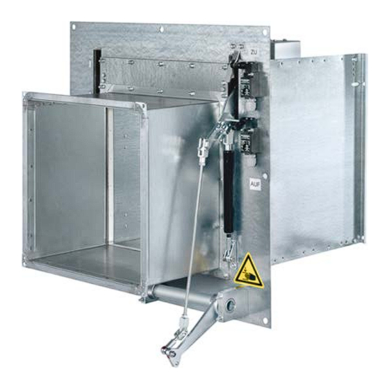
Technical data KA-EU without electric blade opening actuator 2.2 KA-EU without electric blade opening actuator Dimensions [mm] Fig. 2: KA-EU Casing 1.11 Limit switch CLOSED position Damper blade 1.12 Limit switch OPEN position 1.13 Mounting plate Electromagnet with cover 1.14... - Page 10 No. of electromagnets Distance X between magnets Centrally aligned [mm] The magnets should be accessible for maintenance purposes even after the KA-EU has been installed (for maximum wall thickness, see table ). Fig. 3: KA-EU space requirements for opening lever 1.15 Opening lever Standard position of the opening lever 1.15...
-
Page 11: Ka-Eu With Electric Blade Opening Actuator
B [mm] 250–600 1000 1100 1200 No. of electromagnets Distance X between magnets Centrally aligned [mm] The magnets should be accessible for maintenance purposes even after the KA-EU has been installed (for maximum wall thickness, see table ). Fire damper KA-EU... - Page 12 Technical data KA-EU with electric blade opening actuator Fig. 5: Positions of the electric blade opening actuator Bottom centre (standard) Bottom right Top left (only where B ≥ 700 mm) 1.17 Junction box Bottom left (only where B ≥ 700 mm) 1.18...
-
Page 13: Dimensions And Weights
Possible Possible 1000 1100 1200 Not possible Possible Possible 1000 1100 1200 Not possible Possible Possible 1000 1100 1200 KA-EU with electric blade opening actuator: weight + 11 kg. Centre position (standard) is possible for all dimensions. Fire damper KA-EU... -
Page 14: Attachments
Not possible Possible Possible 1000 1100 1200 KA-EU with electric blade opening actuator: weight + 11 kg. Centre position (standard) is possible for all dimensions. 2.5 Attachments Limit switch Standards and guidelines IEC/EN 60947-5-1, VDE 0660-200 and others Construction... - Page 15 At 24 V (AC/DC) min. 100 mA Protection level IP 54 IEC protection class Contact Type 2.B.H.V Potential-free switching contact Probe and capillary tube Copper Max. sensor temperature Scale value + 15% Ambient temperature -30 to 80 °C -15 to +80 °C Fire damper KA-EU...
- Page 16 Operating temperature 5 to 40 °C Casing and cover Plastic Installation Surface mounting Cable entry 10 × M20 × 1.5 Dimensions B × H × D 180 × 260 × 110 mm 4 × Æ4.0 mm Fixing Fire damper KA-EU...
-
Page 17: Transport And Storage
its packaging). Do not store it below 5 °C or above 50 °C. Bracing aid Fire dampers in the KA-EU series are supplied with a bracing aid (1.19). Fig. 6: Bracing aid KA-EU Damper blade 1.19 Bracing aid... -
Page 18: Structure And Function
BMS. Pressing the push through ducting. button interrupts the power supply to the electromag- nets, and the gas struts close the KA-EU as a conse- During normal operation, the damper blade is open quence. to enable air passage through the extract air system. -
Page 19: Push Button
DKT 2.2_A and DKT 2.3_R. Push button DKT 2.2_A is used for closing the KA-EU damper blade. Push button DKT 2.3_R is used to open the KA-EU damper blade with the electric blade opening actuator. -
Page 20: Installation
Sharp edges, sharp corners and thin sheet metal parts may cause cuts or grazes. – Be careful when carrying out any work. – Wear protective gloves, safety shoes and a hard hat. Fire damper KA-EU... -
Page 21: General Installation Information
Design and install the ventilation system in such a way that the KA-EU cannot be damaged due to pressure surges in the ventilation system. Protect the fire damper from humidity and conden- ... - Page 22 (note the marking on the blade opening lever 1.7 and the angle joint 1.52). Screw and tighten the locking nut M8 1.36 to the threaded end on the angle joint 1.52, see Fig. 9 Detail J. Fire damper KA-EU...
- Page 23 Fig. 9: Installing the gas strut Damper blade 1.21 Mounting bracket Blade opening lever 1.22 Bolt Gas strut (from B ≥ 700 mm to gas struts) 1.23 Locking spring 1.10 Spring tab bolt 1.24 Gas strut adjustment 1.20 Joint head Fire damper KA-EU...
- Page 24 Loosen the nut (1.36) on the opening lever (1.15) and remove the opening lever. Retain the opening lever and nut for later use. 1.10 1.12 1.15 1.36 1.7 1.15 Fig. 10: Opening the fire damper Damper blade 1.12 Limit switch OPEN position Setting lever 1.15 Opening lever 1.10 Spring tab bolt 1.36 Fire damper KA-EU...
- Page 25 Reinsert the bracing aid (1.19) and use it to protect the casing (1.1) of the fire damper against deformation while it is being mortared in. 1.19 9.3.2 1.19 9.3.2 Fig. 11: Bracing aid Casing 1.19 Bracing aid Damper blade 9.3.2 Bracing provided on site Fire damper KA-EU...
- Page 26 Use threaded rods (5.4), anchors (5.12), washers and nuts (5.13) to fix the mounting plate (1.13) to the solid wall (3.1) or solid ceiling slab (4.1). Fig. 13: Installation in solid wall (with anchors – concrete wall) KA-EU Threaded rod 1.13 Floor mounting plate 5.12 Anchors Solid wall 5.13 Washer and nut Fire damper KA-EU...
- Page 27 Use dry wall screws (5.1) to fix the mounting plate (1.13) to the lightweight partition wall or compartment wall (3.2). Fig. 15: Installation in lightweight partition walls (with dry wall screws) KA-EU Lightweight partition wall or compartment wall 1.13 Floor mounting plate Dry wall screw Fire damper KA-EU...
- Page 28 – 4 × M10 or at least 4 × ∅6 × 70 6 × M10 or at least 6 × ∅6 × 70 – – – 4 × M10 or at least 4 × ∅6 × 70 Fire damper KA-EU...
-
Page 29: After Installation
Ä 40 or Ä 42 . sary, Test the function of the fire damper Ä 57 . Connect the ducting. Install the capillary tube sensor 38 . Ä 46 or Establish the electrical connection, Ä 50 . Fire damper KA-EU... -
Page 30: Solid Walls
Fix the mounting plate to the wall, either with threaded rods (push through) or with suitable anchors (suitability certificate). Ä 25 . Protect the damper casing against deformation, Close off the perimeter gap with mortar. Fire damper KA-EU... -
Page 31: Solid Ceilings
Damper blade Installation side Ⓐ Mortar or concrete Operating side Ⓑ Fig. 19: Mortar-based installation into solid ceiling slab, suspended KA-EU Solid ceiling slab 1.13 Floor mounting plate Ⓐ Installation side Mortar or concrete Operating side Ⓑ Personnel: Fire damper KA-EU... - Page 32 No distance required between the mounting plates of two fire dampers Each KA-EU fire damper to be installed in an individual installation opening Sufficient clearance for the movement of the manual opening lever or of the electric blade opening actuator, see ...
-
Page 33: Lightweight Partition Walls / Compartment Walls With Metal Support Structure And Cladding On Both Sides
Cladding, fire resistant, on both sides of the facturer's information. metal stud system If the wall thickness is > 100 mm, extend the width of the fixing block so that it equals the inside dimension of the UA section. Fire damper KA-EU... - Page 34 If the wall thickness is > 100 mm, extend the 7.24 Fixing block** for the electric blade opening width of the fixing block such that it equals the actuator; actuator positioned in the centre inside dimension of the UA section. Fire damper KA-EU...
- Page 35 Trim panels have to be screw-fixed to the support structure Erecting a wall and creating an installation opening Erect the lightweight partition wall according to the manufacturer's instructions and create an installation opening, see Fig. 20 Fire damper KA-EU...
-
Page 36: Mortar-Based Installation
No distance required between the mounting plates of two fire dampers Each KA-EU fire damper to be installed in an individual installation opening Sufficient clearance for the movement of the manual opening lever or of the electric blade opening actuator, see ... - Page 37 6 × 70 mm to the metal support structure; make sure that the mounting plate (1.13) rests on the face of the wall. Protect the damper casing against deformation, Ä 25 Close off the perimeter gap with mortar Fire damper KA-EU...
-
Page 38: Installing The Capillary Tube Sensor
The following points must be observed when installing the capillary tube sensor: The scope of supply of the KA-EU includes a capillary tube sensor. Depending on the installation location, additional capillary tube sensors (part no. M536KA0) may be required. For more installation examples, see Fig. - Page 39 Insert the capillary tube sensor with the sensor probe into the protective coil and fix it in place with the two screws (9.7) Fig. 24: More installation examples KA-EU 10.1 Cooker hood TLR 72 capillary tube sensor 10.2 Cooker Capillary tube sensor (not required for an F90 fire- resistant shaft) Fire damper KA-EU...
-
Page 40: Installing The Electric Blade Opening Actuator
Unscrew the hexagon screws (1.38) on the cover (1.39) and feed the wires (1.37) through the conduit in the bottom of the junction box (1.17). Installation position 1.37 Wire 1.37 Wire (red) (black) Bottom centre Terminal 20 Terminal 21 Fire damper KA-EU... - Page 41 4 wall plugs and screws 10 × 70 mm (1.51) or threaded rods M10 (push through). Use the drilled holes in the actuator mounting plate for fixing it to the wall or ceiling slab. Fire damper KA-EU...
-
Page 42: Left Side Or Right Side Installation
Connect the FSM 1 control unit, see Connect and set the limit switches, see Ä 54 . Ä 55 . Set the interlock, see Ä 57 . Test the function of the fire damper, see Fire damper KA-EU... - Page 43 8 nuts M10 (to be provided by others) Push the counter bearing (1.42) onto the adjustment bar (1.45) and up to the bracket (1.41) of the actuator mounting plate (1.46). Then fix it with three Allen screws M6 × 25 mm (1.47). Fire damper KA-EU...
- Page 44 Once the electric blade opening actuator has been installed, you have to make the electrical connec- tions before you start operating the damper. If you fail to electrically connect the actuator, it may become damaged when the damper blade closes. Fire damper KA-EU...
-
Page 45: Connecting The Ducting
Ducting must be installed in such a manner that it does not impose any significant loads on the fire damper in the event of a fire. The expansion of ducts in the event of a fire can be compensated by brackets and turns, Fig. 35 . Fire damper KA-EU... -
Page 46: Electrical Connection
Functional description and electrical connection The FSM 10 control and operating unit is used to close the KA-EU and display the status of the capillary tube sensors. It features a push button for closing the KA- EU as well as a red LED, which only illuminates if the connected TLR capillary tube sensors are triggered. - Page 47 Θ Θ N PE N PE N PE L1 N PE 230V AC Fig. 37: Connection diagram for FSM 10 control and operating unit (example) Flink fuse 500 mA I_OPEN Close Optional DKT 2.2 A push button Fire damper KA-EU...
- Page 48 Contacts 13–14 open Contacts 15–16 open Control and operating unit status indicators Explanation LED (red) Illuminated Push button for closing the KA-EU has been pressed LED (red) Illuminated TLR has been triggered LED (red) Illuminated Cable between TLR and FSM 10 has been cut...
- Page 49 The stripping length of 11 to 13 mm must be observed. It is essential to use wire end ferrules when using flexible wires. TLR 72 11 – 13 SW 24 < 3 Fig. 38: TLR 72 electrical connection Fire damper KA-EU...
-
Page 50: Fsm 1 Control Unit And Electric Blade Opening Actuator
LED and re-establishes the power supply to the electromagnets. Pressing the ‘Reset’ push button on the FSM 1 control unit then opens the KA-EU again with the electric blade opening actuator. Pressing the ‘Test’ push button interrupts the power supply to the In the case of a remote reset (DKT 2.3_R push... - Page 51 12 13 L1 N PE 230V AC 20 21 N PE N PE Fig. 40: Connection diagram for FSM 1 control unit with electric blade opening actuator (example) 230 V supply Operation 230 V electromagnet End position OPEN Fire damper KA-EU...
- Page 52 Optional DKT 2.3_R push button for resetting to the fully open operating state Optional DKT 2.2_A push button for remote clo- sure triggering 230 V AC is applied to FSM 1: KA-EU 100% open position Contacts 12–13 open Contacts 12–14 closed Contacts 15–16 closed Contacts 15–17 open Contacts 29–30 closed...
- Page 53 The stripping length of 11 to 13 mm must be observed. It is essential to use wire end ferrules when using flexible wires. TLR 72 11 – 13 SW 24 < 3 Fig. 41: TLR 72 electrical connection Fire damper KA-EU...
-
Page 54: Settings
Unscrew the two screws 1.28. The limit switch is moved about 5 mm away from the transmitter on the bracket 1.29. Tighten the screws 1.28 again. If necessary, repeat until the switching point is correct. Fire damper KA-EU... -
Page 55: Setting The Interlock (Only With Electric Blade Opening Actuator)
The spring (1.31) has to pull on the lever (1.32) and pull the spring tab bolt (1.10) out of the spring tab (1.30). The functioning can be adjusted using the adjusting nut (1.35) (direction of rotation way from fork head). Checking the locking/unlocking by repeatedly moving the threaded rod back and forth. Fire damper KA-EU... -
Page 56: Setting The Electromagnets
Replace the magnet cover (1.3.1). Fix the magnet cover (1.3.1) with the four screws M 6 × 25 mm (1.3.3). Only tighten the screws (1.3.3) slightly. Tighten the cable gland (1.3.2). Carry out a functional test. Fire damper KA-EU... -
Page 57: Functional Test
Checking all screw-fixed parts for secure seating. Checking the gas strut(s) for damage. Checking the interior of the damper for contamina- tion (inspection access panel in the duct). Switching the fan on again. Fire damper KA-EU... -
Page 58: Ka-Eu With Fsm 10 Control And Operating Unit
Closing the damper blade Close the fire damper by pressing the push button "Close KA-EU" (9.11) on the FSM 10 control and operating unit. The damper blade (1.2) closes automatically and the spring tab bolt (1.10) locks on to the spring tab (1.30). - Page 59 Functional test KA-EU with FSM 10 control and operating unit Fig. 46: Opening the damper blade Damper blade 1.15/1.16 Opening lever Blade opening lever 1.30 Spring tab 1.10 Spring tab bolt 1.36 1.12 Limit switch for damper blade position OPEN Opening the damper blade Attach the opening lever (1.15) or (1.16) to the blade opening lever (1.7) and secure it with a nut (1.36).
-
Page 60: Ka-Eu With Electric Blade Opening Actuator And Fsm 1 Control Unit
Functional test KA-EU with electric blade opening actuator and F... 11.2 KA-EU with electric blade opening actuator and FSM 1 control unit Fig. 47: Closing the damper blade Damper blade 1.30 Spring tab 1.10 Spring tab bolt 9.12 'Test' push button on FSM 1 control unit 1.12... -
Page 61: Functional Test With Thermal Release
The damper blade is opened as described above. NOTICE! The 'Reset' push button (9.10) on the capillary tube sensor is only used to reset the capillary tube sensor after a thermal release; it has no fire protection func- tion. Fire damper KA-EU... -
Page 62: Commissioning
During normal operation, the fire damper is open to allow air to pass through the ventilation system. If the temperature in the ducting rises in the event of a fire (≥ 72 °C), the thermal release mechanism is trig- gered and closes the damper blade. Fire damper KA-EU... -
Page 63: Maintenance
EN 13306 DIN 31051 Maintenance The fire damper and the electric blade opening actuator are maintenance-free with regard to wear but fire dampers must still be included in the regular cleaning of the ventilation system. Fire damper KA-EU... -
Page 64: Cleaning The Fire Damper
Reconnect the power supply and carry out a functional test. Once the bolt (1.22) has been removed, the shut-off unit can be swivelled over the closed position. Swivelling past the closed position can damage the damper and should be avoided. Fire damper KA-EU... -
Page 65: Maintenance
Spring tab bolt locks the CLOSED position into the CLOSED of the damper blade position and locks the on the gas pressure damper blade absorber Repair or replace the fire damper. × = Required + = Recommended Fire damper KA-EU... - Page 66 Replace the limit switches Function of limit switch Function OK CLOSED Function of the external Function OK Determine and eliminate signalling (damper blade the cause of the fault position indicator) × = Required + = Recommended Fire damper KA-EU...
-
Page 67: Troubleshooting
FSM 1 control unit, proceed according to the tables below. FSM 10 control and operating unit Fault Cause Measure Red TLR LED is illumi- The push button "Close KA-EU" or DKT Release push button. nated. 2_2A is pressed. - Page 68 / F2 800 mA fast-acting The electromagnet is not supplied with (electromagnet 230 V) power. Ä 56 The damper blade opens, Electromagnet(s) is(are) not fully reached. Adjust electromagnets, remains briefly open, then closes again. Fire damper KA-EU...
-
Page 69: Decommissioning, Removal And Disposal
Disconnect the wiring. Remove the ducts. Close the damper blade. Remove the fire damper. Disposal For disposal, the fire damper must be disassembled. ENVIRONMENT! Dispose of electronic components according to the local electronic waste regulations. Fire damper KA-EU... -
Page 70: Index
Transport damage............. 17 Hotline................. 3 Troubleshooting............67 Inspection..............63 Warranty claims............3 Installation side............ 9 , 11 Weights..............Installation situations..........20 Interlock..............55 Licence plate............... 8 Lightweight partition walls with metal support structure and cladding on both sides......Fire damper KA-EU... - Page 71 Fire damper KA-EU...
- Page 72 TROX GmbH Phone: +49(0)2845 2020 Heinrich-Trox-Platz +49(0)2845 202265 47504 Neukirchen-Vluyn Email: trox-de@troxgroup.de Germany http://www.troxtechnik.com © 2022...
Need help?
Do you have a question about the KA-EU and is the answer not in the manual?
Questions and answers