Table of Contents
Advertisement
Quick Links
Driver Card for PM605KT
CBK-109
〈 Technical documentation〉
Read this manual before use
Thank you for purchasing CBK-109
(hereinafter referred to as "this product").
*"This product" is a generic term that includes accessories
such as screws.
Applicable MDR models
CBK-109FN / CBK-109FP ... PM605KT
・
・ CBK-109BN / CBK-109BP ... For builtin brake version
Driver
□(F/B)□(N/P)
Before using this product, carefully read this user manual and fully
understand the content.
Keep this document readily accessible for future reference.
For more details of PM605KT, please download the user manual rom our web page.
ITOH DENKI
https://www.itoh-denki.com/en/documents/technical-documentation/circuit-boards
ITOH DENKI
ITOH DENKI
ITOH DENKI
Driver card
Original notice - A1.8
Advertisement
Table of Contents

Related Manuals for ITOH DENKI CBK-109


Summary of Contents for ITOH DENKI CBK-109
- Page 1 Driver Card for PM605KT CBK-109 Driver 〈 Technical documentation〉 Read this manual before use Thank you for purchasing CBK-109 □(F/B)□(N/P) (hereinafter referred to as “this product”). *“This product” is a generic term that includes accessories such as screws. Applicable MDR models CBK-109FN / CBK-109FP ... PM605KT ・...
-
Page 2: Table Of Contents
Check Product …… 16 6. Installation/Wiring …… 18 6-1. Preparation to install driver cards …… 19 6-2. Mounting driver cards …… 19 6-3. CBK-109 Functions list / Wiring …… 19 7. Control/Operation …… 22 7-1. Transfer direction settings …… 23 7-2. Error signal …… 23 7-3. Motor pulse signal …… 24... -
Page 3: Product Range
Product range CBK-109 Technical documentation Product range solutions Standard circuit board DC Brushless 90° transfer HBR-605 CB016 CB016B F-RAT-S250 CBM-105 CBR-306 CBM-105 HBR-605 F-RAT-S300 CBM-105 External Integrated CBR-306 Replacing circuit board CBK-109 CBK-109B circuit board CB030 CBK-109 CB016B F-RAT-NX75 HBM-201 CB018 IB-E IB-P... -
Page 4: Introduction
Signal input/output type Driver card model In this manual, [CBK-109FN] / [CBK-109FP] and [CBK-109BN] / [CBK-109BP] are desribed as [CBK-109]. [CBK-109FN] / [CBK-109FP] and [CBK-109BN] / [CBK-109BP] are described separately, when needed. Original notice - A1.8... -
Page 5: Procedures From Installation To Operation
Procedures from installation to operation CBK-109 Technical documentation 2. Procedures from installation to operation Procedures from installation to operation Read this manual Start using only after you have understood the product s functions, and safety precautions. Advance preparation Prepare the 24 VDC power supply, such as DC power supply units. -
Page 6: Safety Precautions
3. Safety precautions CBK-109 Technical documentation 3. Safety precautions Refer to 5. Check Product (P.16) for parts name. Original notice - A1.8... - Page 7 Danger level CBK-109 Technical documentation 3. Safety precautions Danger level To prevent hazards to users and/or others, and/or damage to property in advance, we explain important precautions to be followed securely as below. ■ We categorize the degree of hazard and/or damage that may result if a user disregards the description, and operates the product improperly, using and explaining the following symbols.
-
Page 8: General Precautions
General precautions CBK-109 Technical documentation 3. Safety precautions 3-1. WARNING General precautions Do not use the product near places subject to explosive, flammable gas, and/or corrosive atmosphere, and/or combustible materials. Failure to follow this could result in explosion, fire, electric shock and/or injury. When using the product in places where serious accidents and/or damage may possibly occur, install backup and/or fail-safe functions systematically. -
Page 9: Precautions On Installation
General precautions CBK-109 Technical documentation 3. Safety precautions 3-1. CAUTION General precautions Securely wire each connector to the connection parts. Improper wiring could result in electric shock and/or malfunction. Do not turn on/off relays and/or contactors near power cables, signal cables, and/or driver cards. -
Page 10: Precautions On Wiring
Precautions on wiring CBK-109 Technical documentation 3. Safety precautions 3-3. CAUTION Precautions on wiring Perform wiring when the power is shut off. Failure to follow this could result in electric shock and/or accidents due to unexpected operation. When attaching or removing connectors, turn off the power first, securely hold connectors, and perform operation. -
Page 11: Precautions On Maintenance And Inspection
Precautions on maintenance and inspection CBK-109 Technical documentation 3. Safety precautions 3-5. WARNING Precautions on maintenance If any abnormalities are found, do not use this product until the causes have been eliminated completely . Using this product with unattended abnormalities could result in not only damage to the devices, but also unexpected accidents. -
Page 12: Advance Preparation
4. Advance preparation CBK-109 Technical documentation 4. Advance preparation Original notice - A1.8... - Page 13 Items to be prepared by customers CBK-109 Technical documentation 4. Advance preparation Configuration example power supply Controller, such as PLC Breaker Safety circuit 24V DC power supply unit CBK-109 ■ As for the sensor input, and input/output signals of driver cards, adopt the number of inputs/outputs based on operation. ■ The safety circuit includes the emergency stop equipment and magnet contactor.
- Page 14 Male side Model 12P extension cable length Female side ACE-CBM-G1200 L= 1200mm L= 2000mm ACE-CBM-G2000 ±5 ■ CBK-109:13P extension cable (only for the brake type) Male side Model 13P extension cable length Female side ACE-CBK-H1000 L= 1000mm L= 2000mm ACE-CBK-H2000 ±5...
- Page 15 Emergency stop equipment CBK-109 Technical documentation 4. Advance preparation ⑦ Emergency stop This product does not include the emergency stop equipment. equipment Customers must make sure to install it. Emergency stop equipment To this product AC power supply 24V DC power supply unit Safety circuit Breaker Checking the Regarding equipment where this product is incorporated, check that a breaker with ⑦-1...
-
Page 16: Check Product
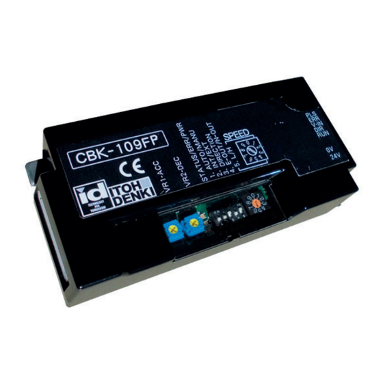
5. Check Product CBK-109 Technical documentation 5. Check Product Original notice - A1.8... - Page 17 Checking the model CBK-109 Technical documentation 5. Check Product Checking the model Unpack the product, and check that the product model is what you ordered. Model CBK-109□□ SPEED V-IN Model description sample CBK-109 ※ ① Driver card specifications ② Input and output signals ・ F … Standard ・ N … NPN input/output ・...
-
Page 18: Installation/Wiring
6. Installation/Wiring CBK-109 Technical documentation 6. Installation/Wiring Original notice - A1.8... -
Page 19: Preparation To Install Driver Cards
Mounting driver cards CBK-109 Technical documentation 6. Installation/Wiring 6-1. Hole processing on frames and control panel Preparation to install Perform mounting processing on the frames and control panel by reference to driver cards the mounting holes for driver cards. ■ Mount driver cards on a flat surface where heat can be released easily. ■ Prevent chips generated during processing from entering driver cards. -
Page 20: Cbk-109 Functions List / Wiring
CBK-109 Functions list / Wiring CBK-109 Technical documentation 6. Installation/Wiring ③ VR (Volume) Minimum Maximum Factory References setting (Full in a counter-clockwise (Full in a clockwise direction) direction) 0.1 seconds 1 Acceleration time from RUN signal until specified speed 2.5 seconds Minimum ー 0.1 seconds Deceleration time from STOP signal until stop 2.5 seconds... - Page 21 CBK-109 Functions list / Wiring CBK-109 Technical documentation 6. Installation/Wiring Connect the 24 VDC and 0 VDC cables to CN1 (2 contacts). Wiring of Power connector power connector (CN1) (CN1 ) Do not connect multiple power cables to one contact. ■ Failure to follow this could result in electric shock, short circuit, and/or damage due to the capacity of connectors being exceeded.
-
Page 22: Control/Operation
7. Control/Operation CBK-109 Technical documentation 7. Control/Operation Original notice - A1.8... -
Page 23: Transfer Direction Settings
CBK-109 settings CBK-109 Technical documentation 7. Control/Operation The MDR’s direction of rotation is determined by a combination of SW1#3 and CN2#2. 7-1. MDR transfer direction settings using SW1#3 and CN2 Transfer direction settings SW1#3 SPEED V-IN CN2# SW1#3 CN2# ■ The transfer direction cannot be changed using SW1#3 during transfer (while the MDR is running). -
Page 24: Motor Pulse Signal
CBK-109 seittings CBK-109 Technical documentation 7. Control/Operation ・The motor pulse signal for the MDR is output from CN2#5. 7-3. Motor pulse signal ・Output is a NPN open collector output of 2-pulse signal per rotation of the internal motor. Accuracy: ±3% Internal speed settings CN2#5 External... -
Page 25: Maintenance/Inspection
8. Maintenance/Inspection CBK-109 Technical documentation 8. Maintenance/Inspection Original notice - A1.8... -
Page 26: Error Details
Error details on CBK-109 CBK-109 Technical documentation 8. Maintenance/Inspection 8-1. Error details on CBK-109 Error details Errors can be checked by PWR (green), ERR (red), and signals from CN2#4. ■ When error signals have been released using CN2#1 (RUN / STOP), the MDR instantly starts up when RUN is input. -
Page 27: Error History
CBK-109 Error history CBK-109 Technical documentation 8. Maintenance/Inspection 8-2. CBK-109 Error history Error history When the thermal error/lock error/low voltage error/back EMF error occurs during operation, the error type and the number of occurrences are indicated using LEDs [ERR (red), STATUS (orange)]. ■ The error history [STATUS (orange)] is indicated on LEDs only when an error occurs. -
Page 28: Error Time Chart
Error time chart CBK-109 Technical documentation 8. Maintenance/Inspection 8-3. CBK-109 Error time chart Error time chart For details on error conditions, recovery conditions, and LED indication, refer to each section. *The error time chart is described as an example when the SW1#4 is ON (output under the normal condition). - Page 29 Error time chart CBK-109 Technical documentation 8. Maintenance/Inspection Driver card/MDR thermal error Release the error RUN signal RUN signal (CN2#1) Recovery STOP Abnormal temperature Driver card/ Recovery MDR thermal temperature ※2 1.0sec ※1 Output Error output (CN2#4) Open (red) ※1 An error occurs when the driver card/MDR temperatures have increased to an abnormal level or higher for 1.0 seconds.
-
Page 30: Troubleshooting
⇒ Check the wire diameter and wirings. ・Check that CBK-109 is not too far from the power supply. (Check if the voltage has not dropped.) ・Check if the product is being used in the ambient temperature range between 0 and 40ºC. -
Page 31: Specifications
Specifications CBK-109 Technical documentation Specifications Original notice - A1.8... -
Page 32: Product Specifications
Set the maximum output current to option brake brake brake 25mA or less) CBK-109□P (PNP version) ・ Servo lock brake activates after activating dynamic brake for ※1 200msec. <4V to the lower level Logic voltage level ・ Maximum 1A current flows. -
Page 33: Speed Settings And Characteristics
4.51 11.7 149.1 4.51 149.1 10.2 4.57 151.1 4.57 151.1 4.63 153.2 4.70 155.3 PM605KT (Nominal speed : 28) with CBK-109 8.00 Speed vs Tangential force Current vs Tangential force 35m/min 7.00 35m/min 6.00 26.2m/min 5.00 26.2m/min 4.00 14.6m/min 14.6m/min 3.00... - Page 34 2.54 19.1 83.9 2.57 16.3 85.1 2.57 13.6 85.1 2.61 10.9 86.2 2.64 87.4 PM605KT (Nominal speed :55) with CBK-109 8.00 Speed vs Tangential force Current vs Tangential force 65.4m/min 7.00 65.4m/min 6.00 49.1m/min 49.1m/min 5.00 27.2m/min 4.00 3.00 27.2m/min 2.00...
-
Page 35: Inclined Belt Conveyor - Angle Capacity Calculation
Specifications CBK-109 Technical documentation Inclined belt conveyor – angle capacity calculation Calculation method The motorized roller capacity for driving an inclined belt conveyor can be estimated thanks for the below relation : F(roller) = μ x 9.8 x M x cos θ + 9.8 x M x sin θ + F(belt) - Page 36 Specifications CBK-109 Technical documentation Example of calculation Conveyor design and condition of usage - Motorized roller used: PM605KT speed code 55. - Temperature: 25°C. - Load: plastic boxes 50kg. - Belt: μ = 0.05 - Conveyor speed 60 m/min. -> Tangential force at nominal point: 76.9 N - Empty conveyor load: Current consumption when empty: 1A ->...
- Page 37 Specifications CBK-109 Technical documentation Calculation F(roller) = μ x 9.8 x M x cos θ + 9.8 x M x sin θ + F(belt) 76.9 = 0.05 x 9.8 x 50 x cos θ + 9.8 x 50 x sin θ + 7 ->...
- Page 38 Technology for tomorrow ITOH DENKI 490 Av. des Jourdies - P.A.E. les Jourdies 74800 St Pierre en Faucigny - France Phone : +33 (0)4 50 03 09 99 Fax : +33 (0)4 50 03 07 60 www.itoh-denki.com Original notice - A1.8...
Need help?
Do you have a question about the CBK-109 and is the answer not in the manual?
Questions and answers