Table of Contents
Advertisement
Quick Links
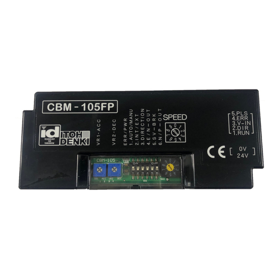
CBM-105FN/FP
Driver Card Manual
Features:
Adjustable acceleration and deceleration
time (0 to 2.5s)
Stable speed operation
Manual or automatic recovery of the thermal
overload device
One (1) rotary switch to select up to 10
different fixed speeds or external voltage
input for up to 20 fixed speeds
Forcibly stops the motor if motor lock last for
4 seconds or thermal overload error lasts for
1 second or more.
Two (2) LEDs (red & green) to identify the type
of error and power
Back EMF error for overspeeding protection
Pulse signal output to indicate motor
revolution
Specifications subject to change without notice
2 Great Valley Blvd., Wilkes-Barre, PA 18706
Office Ph: 570-820-8811
Fax: 570-820-8838
www.itohdenki.com
Servo brake control allows product to maintain
its position after run signal is removed
Error output selection for output in normal or
abnormal status
Lead free design; RoHS compliant
Low Voltage Protection reacts when
Sustained low voltage (less than 15V DC) for
at least 1 second
Fluctuating voltage dropping below 15V DC,
5 times within 0.5 second
External Direction control
When external DIR signal is changed while
motor is running, the motor stops for 0.5
second, then runs again in opposite direction
Advertisement
Table of Contents

Related Manuals for ITOH DENKI POWER MOLLER 24 CBM-105FN


Summary of Contents for ITOH DENKI POWER MOLLER 24 CBM-105FN
- Page 1 CBM-105FN/FP Driver Card Manual Features: Adjustable acceleration and deceleration Servo brake control allows product to maintain time (0 to 2.5s) its position after run signal is removed Stable speed operation Error output selection for output in normal or Manual or automatic recovery of the thermal abnormal status overload device Lead free design;...
-
Page 2: Specifications
Specifications Connections: Specifications subject to change without notice 2 Great Valley Blvd., Wilkes-Barre, PA 18706 Office Ph: 570-820-8811 Fax: 570-820-8838 www.itohdenki.com... -
Page 3: Control Wiring
Specifications Connections: 5 PIN connector Male Connector on Card Female Connector for Wiring CONTROL WAGO #733-365 WAGO #733-105 Description +24V DC or 0V input (RUN) +24V DC or 0V input (DIR) Wire size: 0 ~ +10V DC input (V-IN) 28~20AWG +24V DC or 0V output (ERR) 0V output (PLS) Control Wiring:... -
Page 4: Applicable Models
Specifications 24V DC ±10% input Electrical: - Battery - Power Supply: fullwave rectified with smoothed current and <10% Ripple - Supply should be rated at 5 A or more and should not be effect by peak current of 20 A for 1 msec. Power ON delay <1s 4A locking current Input signal level for activation - 0V (3V or less) for NPN... -
Page 5: Operation
Operation DIP Switches (SW1) – User Settings: DIP-SW Function ON Setting OFF Setting Initial Setting Thermal device / low Automatic voltage / back EMF Manual (Thermal restarts 1 min recovery after cool down) External Internal Speed change selection (0~10V DC applied) (Rotary switch) DIR* FS/FP - CCW... - Page 6 Operation motor pulse output signal: NPN (0V) output from CN2-5 Two (2) pulses per motor revolution NPN (0V) / PNP (24V) inputs: The card(s) are ordered with the inputs preset from the factory – ALL NPN or ALL PNP. The model designation will show the factory preset. •...
- Page 7 Operation Led and error indications: LED 1: Green (power) LED 2: Red (error condition) *To reset an error condition: Remove input signals; then reapply an input signal to either CN2-1 (RUN) or CN2-2 (DIR) **If thermal device recovery is set for automatic, the error will reset 1min after the temperature has reached operating range, and as long as no external input has been applied back emf error: If card detects back EMF over 40V DC for 2sec or 60V DC for 0.1sec the motor will stop...
- Page 8 Operation speed change tables: Internal External Surface speed* (ft/min +/- 5%) Surface Speed* (ft/min ±5%) Control Control Rotary PM486FE-17 PM486FE-60 PM486FE-100 PM486FE-17 PM486FE-60 PM486FE-100 0~10V DC Switch (3-stage) (2-stage) (1-stage) (3-stage) (2-stage) (1-stage) 55.4 196.8 433.6 9.6~9.9 55.4 196.8 433.6 50.5 180.4 433.6...
-
Page 9: Troubleshooting
troubleshooting power moller does not run: -Check that the green LED 1 illuminated to indicate the card is receiving 24 V DC Power -Check that the voltage to the card is stable 24V DC, see page 4 -Check the wiring to CN1 is properly wired and in the correct position, see page 3 -Check the run signal is properly wired and in the correct position of CN2-1, see page 3 -Check the signal injected into CN2-1 is the proper voltage: 0V for NPN or 24V for PNP -Check if 0V DC is used for CN2-1 run signal that it is common to 0V DC in CN1-2, see... - Page 10 Troubleshooting Reversing not achieved: -If using 0V DC inserted into CN2-2 to change direction, check that the 0V DC is CW / CCW common to the 0V DC on CN1-2, see page 3 for wiring Using external -Check the wiring is properly connected and inserted into CN2-2 signal -Check that the internal dip switch under the black plastic cover is set to the proper position: up for NPN (0V) and down for PNP (24V).
-
Page 11: Installation Precautions
Installation Precautions IMPORTANT: PLEASE READ BEFORE ISNTALLATION Precaution Action Reason If the voltage drops below 15V DC and remains low If the power supply is not sized for 1s, then the low voltage error will appear. appropriately for the number of If the voltage drops below 15V DC five times in 0.5s, Power supply cards/rollers it provides power to,... -
Page 12: Revision History
REVISION HISTORY Revision Number Change 12-0508 Initial Document 12-0723 Added troubleshooting section 12-0810 Changed analog voltage inputs 12-1025 Spelling correction 13-0314 Added auto-sensing input diode recommendation 13-0513 Removed auto-sensing feature 14-1119 Added internal input type switch 2 Great Valley Blvd., Wilkes-Barre, PA 18706 Office Ph: 570-820-8811 Fax: 570-820-8838 www.itohdenki.com...
Need help?
Do you have a question about the POWER MOLLER 24 CBM-105FN and is the answer not in the manual?
Questions and answers