Table of Contents
Advertisement
Quick Links
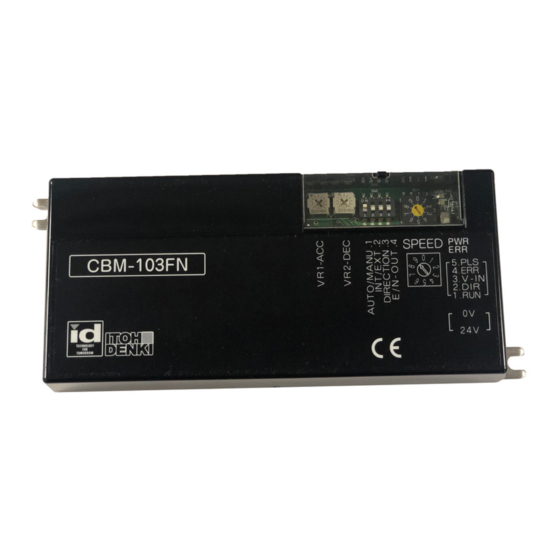
CBM-103FN/FP
Driver Card Manual
Features:
Specifically designed for the KE series Power Moller® family
Adjustable acceleration and deceleration time (0 to 2.5s)
Stable speed operation
Manual or automatic recovery from thermal overload and low voltage
One (1) rotary switch to select up to 10 different fixed speeds
Two (2) LEDs (green & red) to identify error type
Pulse signal output to indicate motor revolution (2 pulses/motor revolution)
RoHS and EMC conformity
Low Voltage Protection
External Direction control
Specifications subject to change without notice
2 Great Valley Blvd., Wilkes-Barre, PA 18706
Office Ph: 570-820-8811
Fax: 570-820-8838
www.itohdenki.com
Advertisement
Table of Contents

Subscribe to Our Youtube Channel
Related Manuals for ITOH DENKI POWER MOLLER 24 CBM-103FN


Summary of Contents for ITOH DENKI POWER MOLLER 24 CBM-103FN
- Page 1 CBM-103FN/FP Driver Card Manual Features: Specifically designed for the KE series Power Moller® family Adjustable acceleration and deceleration time (0 to 2.5s) Stable speed operation Manual or automatic recovery from thermal overload and low voltage One (1) rotary switch to select up to 10 different fixed speeds Two (2) LEDs (green &...
-
Page 2: Specifications
Specifications Connections: 2 PIN Connector Connector on Card Connector for Wiring POWER WAGO #231-432/001-000 WAGO ##231-102/026-000 Description +24V DC Wire size 28~14 AWG 7 PIN Connector Connector on Card Connector for Wiring MOTOR JST #S7B-XH-A JST #XHP-7 Description GND – Grey +12V DC –... -
Page 3: Control Connections
Specifications Control connections: 5 PIN Connector Connector on Card Connector for Wiring CONTROL WAGO #733-365 WAGO #733-105 Description +24V DC (PNP) or 0V (NPN) input – RUN +24V DC (PNP) or 0V (NPN) input – DIR Wire Size: 0 ~ +10V DC input – V-IN (speed variation) 28~20 AWG +24V DC or 0V output –... -
Page 4: Applicable Models
Specifications 24V DC ±10% input Electrical: - Battery - Power Supply: fullwave rectified, smooth current <10% Ripple Power ON delay < 1s 10A locking current Input signals (minimum 2.2mA, maximum 7.3mA) - NPN (0V) - PNP (+24V DC) Output signals (open collector 24V, 25mA or less) - NPN (0V) - PNP (+24V DC;... -
Page 5: Operation
Operation switches: Position Switch Function Initial Setting Down NPN: CBM-103FN Error Output PNP: CBM-103FP Position Switch Function Initial Setting Left Right NPN: CBM-103FN Input Type PNP: CBM-103FP DIP Switches – User Settings: DIP- Initial Function ON Setting OFF Setting Setting Error recovery: Manual Reset Automatic Reset... - Page 6 operation LED AND ERROR INDICATIONS: LED 1: Green (power) LED 2: Red (error condition) Motor pulse output signal 0V (NPN) output from CN2-5 Two (2) pulses per motor revolution Maximum speed pulse frequency approximately 147Hz Specifications subject to change without notice 2 Great Valley Blvd., Wilkes-Barre, PA 18706 Office Ph: 570-820-8811 Fax: 570-820-8838...
-
Page 7: Automatic Recovery
operation error list: Error Description Solution Fuse or temperature > 18A through circuit or Replace Card fuse, blown > 139°C (282°F) Motor disconnected Motor connector(s) Plug in appropriate connectors (CN3 or CN4) unplugged RUN signal turns ON, Stalled motor but motor does not After motor shuts off turn for 1s Motor control circuit... - Page 8 Operation speed change table: Speed (ft/min) +/- 5% Rotary V-IN (V) Switch 1-stage 2-stage 3-stage 9.69 ± 0.25 758.0 199.5 52.5 9.06 ± 0.25 710.6 187.0 49.2 8.44 ± 0.25 663.3 174.5 45.9 7.81 ± 0.25 615.9 162.1 42.7 7.19 ± 0.25 568.5 149.6 39.4...
- Page 9 Operation npn or pnp inputs/outputs: The card(s) are ordered with the inputs/outputs preset from the factory – ALL NPN or ALL PNP. The model designation will show the factory preset. CBM-103FN – NPN input/output type CBM-103FP – PNP input/output type If it is necessary to change the input or output type, the internal dip switch(es) will need to be changed as shown below: 1.
-
Page 10: Installation Precautions
IMPORTANT: PLEASE READ Installation Precautions BEFORE ISNTALLATION Precaution Action Reason If the voltage drops below 15V DC and remains low If the power supply is not sized for 1s, then the low voltage error will appear. appropriately for the number of If the voltage drops below 15V DC five times in 0.5s, Power supply cards/rollers it provides power to,... -
Page 11: Revision History
REVISION HISTORY Revision Change Changed by: Number 11-0914 Initial Document 12-1226 Added autosensing inputs and precautions for electrical potential 13-0314 Added diode recommendation and wiring diagram 13-0514 Removed auto-sensing feature 14-1219 Added internal input type switch Added internal output type switch and mirrored induced and low 15-0409 JC and BB voltage errors...
Need help?
Do you have a question about the POWER MOLLER 24 CBM-103FN and is the answer not in the manual?
Questions and answers