Table of Contents
Advertisement
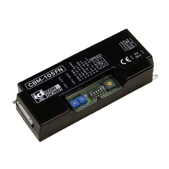
Brushless DC Motor Driver
【CBM-105 FN/FP 】 User Manual
Thank you for purchasing a Itoh Denki CBM-105 series motor
driver.
Please read this manual before operating the product,
and keep this manual readily accessible for reference.
Applicable Power Moller (MDR) models:
PM486FE , PM486FP , PM486FS , PM500FE
PM500FP , PM570FE , PM605FE , PMT42FE
*BR(Brake) and LT(Low temperature) is not available on CBM-105
MDR (Motor Driven Roller)
MDR is DC brushless motorized roller for conveyor.
MDR is defined by Conveyor Equipment Manufacturers
Association (CEMA) and conveyor built by MDR is well
established technology in Material Handling Industry.
ITOH DENKI CO.,LTD.
INDEX
1 .
Safety Instructions
2 .
3 .
Before Operating the Product
3 - 1 .
Mounting
3 - 2 .
Wiring
3 - 3 .
4 .
Functions
5 .
5 - 1 .
5 - 1 - 1 .
5 - 1 - 2 .
5 - 2 .
5 - 3 .
6 .
7 .
8 .
9 .
1 0 .
11 .
Dimension
1 2 .
Product specifications
Standard Accessories
●Power Connector (CN1)
●Control Connector(CN2)
●Mounting screws and nut
Screw : M4×15
Nut : M4
No.561
( 1 )
( 1 )
( 1 )
( 1 ) ~ ( 2 )
( 2 )
( 2 ) ~ ( 3 )
( 3 )
( 3 ) ~ ( 5 )
( 3 ) ~ ( 5 )
( 6 )
( 6 )
( 6 )
( 7 )
( 7 ) ~ ( 8 )
( 8 )
( 9 )
( 1 0 )
( 1 0 )
×1
×1
×2
×2
Power connector
Control connector
(CN-1)
(CN-2)
1. Safety Instructions
●
Switch off the power, when removing from conveyor, wiring or maintenance is done,
otherwise you have a risk of electrical shock or injury
●
Respect the electrical regulations of the site or equipment, where the product in installed.
(Labor safety and sanitary regulations, electrical equipment technical standard, etc)
●
Operate the motor driver within its intended design and specifications to avoid electrical
shock, injury or fire.
●
Do not disassemble, repair nor modify the product (For which we do not warrant)
It might cause electrical shock, injury or failure.
●
Separately set the circuitry to monitor the important input and/or output signal status,
which might cause accident, because the signal may stay ON or OFF in case of the
CBM-105 driver card failure.
●
Be sure to shut off the power before inserting or removing any connector. Do not wire
connector left in the CBM-105 driver card.
●
Do not drop, give external impact nor pressure to the CBM-105 driver card. If that
happened, do not reuse it.
●
Make sure all the connectors are properly engaged with cables.
●
Make sure the conveyor frame and control box where the CBM-105 driver card is
mounted are grounded.
●
Do not switch ON or OFF the relay or contractor in close proximity to power or signal line,
or the CBM-10 driver card as the generated noise could cause malfunction.
●
Be sure to inject power or input signal for 15msec or over to ensure the proper reaction.
●
Do not remove any connector during operation. It may cause of damage to the driver card
or shorten its life time.
●
Do not shut power off during MDR is running. It may cause of damage to the driver card or
shorten its life time.
●
Do not get on the conveyor if power is ON to the driver cards. Do not turn on power, if
totes are not steady on conveyor. It might cause electrical shock, injury or failure.
●
Do not pull by force the Power Moller to turn.
It may cause of damage to driver card or shorten its life cycle.
●
Without power on to the driver card, dynamic brake or servo brake is not worked.
2. Power
● DC24V battery
● Switching power (24VDC 5A) or smoothed and rectified power
● Smoothed and rectified power (≦ 10% ripple)
※Use stable power supply with 5A or over. The power supply should not be affected
by peak current 20A for 1msec.
3. Before Operating the Product
3-1. Mounting
① Make mounting holes in the conveyor frame to fit the fixing holes in the product.
(See Dimensions in section 11)
※The product's back place should be paid to prevent the metallic dust entry to
the product.
※Make sure the conveyor us adequately grounded.
② Fix the product tightly to the conveyor frame with the supplied mounting screws
and nuts with the recommended fastening torque between 1.5Nm and 1.9Nm.
3-2. Wiring
・ Wiring should be made while the product is not powered.
・ Switch for Run/Stop or CW/CCW is an option and is not supplied.
・ Relay contact or PLC output is available instead of the above switch.
・ Wiring to the supplied connectors should be made before inserting into the driver.
【Wiring diagram】
NPN
CN2
Motor pulse signal output
5.PLS
Error signal output
3.V-IN
0-10V IN
2.DIR
CW/CCW
1.RUN
RUN/STOP
0V
0V
24V
DC24V
CN1
CN2
-1 MDR run and stop (Mandatory) → See section 5
-2 MDR direction (CW/CCW)
*
→ See section 5-2
*Turning direction setting can also be done by dip switch on the PCB.
-3 External speed variation by analog voltage change → See section 5-1
*Speed variation setting also can be done by Rotary Switch on the PCB.
-4 Discharge of error signal → See section 6
-5 Discharge of motor pulse → See section 7
PNP
CN2
Motor pulse signal output
5.PLS
Error signal output
4.ERR
3.V-IN
0-10V IN
2.DIR
CW/CCW
1.RUN
RUN/STOP
0V
0V
24V
DC24V
CN1
(1)
Advertisement
Table of Contents

Related Manuals for ITOH DENKI CBM-105 Series


Summary of Contents for ITOH DENKI CBM-105 Series
-
Page 1: Table Of Contents
Do not disassemble, repair nor modify the product (For which we do not warrant) It might cause electrical shock, injury or failure. Thank you for purchasing a Itoh Denki CBM-105 series motor ● Separately set the circuitry to monitor the important input and/or output signal status, driver. -
Page 2: Power
②Potentiometer (VR) ① Wire 24VDC and 0V to the Power Connector CN1(2P) Connector current capacity is 10A. ※ Default Remarks Avoid wiring causing excessive current. (To the CCW end) (To the CW end) Make sure the +/- wiring is correct. ※ Acceleration from 1... - Page 3 0.1~0.4 0 0.1~0.4 Consult local ITOH DENKI representative in case you use Power Moller with Consult local ITOH DENKI representative in case you use Power Moller with nominal speed not in the above table. nominal speed not in the above table.
-
Page 4: Direction Setting
7. Motor Pulse Signal Output 5-2. Direction Setting Reverse direction by external DIR signal can be permitted even while motor is running. ・ Power Moller’s motor pulse signal is discharged from CN2-5. Power Moller turning direction can be set or changed either internally by integral DIP ・... -
Page 5: Servo Brake
10. Troubleshooting Shut off the power off MDR connector and re-plug connector Discharge Open STOP See section 5 unplugged properly. ※Follow the procedures below without removing plastic cover or modifying the driver card, in case any problem happened. Inject signal RUN-STOP-RUN order to CN2-1 to reset the error and restart. -
Page 6: Err
Headquarters; Itoh Denki Co.,Ltd Phone: +08 (0)790 47 1225 Fax: +08 (0)790 47 1325 www.itohdenki.co.jp Europe, Middle East, Africa: Itoh Denki Europe SAS Phone: +33 (0)4 50 03 09 99 Fax: +33 (0)4 50 03 07 60 www.itoh-denki.com North & South America: Itoh Denki USA,INC Phone: +1 570 820 8811 Fax: +1 570 820 8838...
Need help?
Do you have a question about the CBM-105 Series and is the answer not in the manual?
Questions and answers