Table of Contents
Advertisement
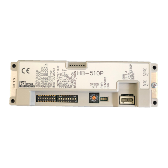
HB-510N/P
Driver Card Manual
What's New:
Designed to be functional with the FS and
FE series motors, as well as the higher
torque series FP
Run Hold timer added to the Forcible RUN
input
Now there is no need for an external
controller/timer with, or awkward
positioning of, a second sensor used for
infeeding the conveyor
Features:
Logic for general zero pressure
accumulation (ZPA) control is built-in
Direct connection for a photo-sensor to
both power it and receive its output signal
Easy connection between adjacent HB-
510s with communication cables
simplifies wiring
Selectable singulated or slug (train)
release modes for ZPA function
Flexible Zone Recognition (patented) to
handle long articles which simultaneously
block multiple sensors
Only available in slug release mode
Specifications subject to change without notice
2 Great Valley Blvd., Wilkes-Barre, PA 18706
Office Ph: 570-820-8811
Fax: 570-820-8838
www.itohdenki.com
Integral indexed rotary switch provides easy
speed adjustment without the need for
"tweaking"
More LED functionality to communicate
operating and error statuses
Selectable automatic or manual recovery for
thermal overload protection
Motor lock protection shuts motor down if it is
locked for at least 4 seconds
Lead free design for RoHS conformity
Synchronized speed variation to
simultaneously adjust the speed of the rollers
with a single external speed control signal
Stable speed function to ensure that different
weight articles travel at the same rate
As long as the load does not exceed the
rated torque for a given speed
Enclosure is made from fire resistant ABS
Advertisement
Table of Contents

Related Manuals for ITOH DENKI POWER MOLLER 24 HB-510N


Summary of Contents for ITOH DENKI POWER MOLLER 24 HB-510N
- Page 1 HB-510N/P Driver Card Manual What's New: Designed to be functional with the FS and Integral indexed rotary switch provides easy FE series motors, as well as the higher speed adjustment without the need for torque series FP “tweaking” Run Hold timer added to the Forcible RUN More LED functionality to communicate input operating and error statuses...
-
Page 2: Table Of Contents
table of contents Subject page Features -What's New -General Features Table of Contents Specifications -Dimensions -User Interface -Standard Conveyor Figuration Connections Installation Precautions Switch Settings -Signal Blocking -Input/Output Settings 9-17 -Timer Settings -Other Settings -Speed Adjustment -Jumper Settings LED and Error Indications Conveyor Zone Configuration 19-22 Connecting to HB-508S... -
Page 3: Specifications
Specifications dimensions: User interface (default settings): standard conveyor configuration - npn output signal types: Specifications subject to change without notice 2 Great Valley Blvd., Wilkes-Barre, PA 18706 Office Ph: 570-820-8811 Fax: 570-820-8838 www.itohdenki.com... -
Page 4: Connections
connections: Male Connector on Card Female Connector for Wiring 2 PIN Connector for Power WAGO #734-162 WAGO #734-102 Description +24V DC ±10% (full-wave rectified, smoothed current <10% ripple) Wire Size 28~14AWG (Ordered Separately) Male Connector on Card Female Connector for Wiring 5 PIN connector for External WAGO #733-335 WAGO #733-105... - Page 5 Connections (Continued): 8 PIN Connector for Male Connector on Card Female Connector for Wiring CN4 & CN5 Communication Cable Molex #52018-8845 RJ-45 Description Sensor signal output Sensor signal input Speed variation signal Wire Size: Error signal 26AWG Drive input Equivalent 8 wire cable Drive output Direction signal Emergency stop signal...
- Page 6 Connections (continued): 9 or 10 PIN Male Connector on Card Female Connector for Wiring connector for Motor JST #S?B-XH-A (? = 9 or 10) JST #XHP-? (? = 9 or 10) Description GND – Grey +12V DC – Blue Motor phase U – Red Wire size: Motor phase V –...
-
Page 7: Installation Precautions
Installation Precautions IMPORTANT: PLEASE READ BEFORE ISNTALLATION Precaution Action Reason -The HB-510 responds to the active signal received from Use a sensor that would have an active the sensor to denote zone occupation. If the incorrect output when the zone is occupied type is used, the HB-510 would “think”... - Page 8 Installation Precautions IMPORTANT: PLEASE READ BEFORE ISNTALLATION Precaution Action Reason Compatibility Please refer to the section: Connecting SPEED, DIR, and E-STOP/GND signals will conflict with HB-508S to HB-508S DO NOT connect an output terminal When the PNP signal is active, the low impedance input will Low impedance (CN2-2, CN2-1) set for PNP directly to draw a high current and subsequently damage the output...
-
Page 9: Signal Blocking
Operation signal block settings: Default Function Switch Setting CN5 (Left) CN4 (Right) CN5 (Left) CN4 (Right) ERR signal transmission Blocked Transmit & Transmit & DIR signal transmission Blocked Receive Receive Transmit & ESTOP signal transmission Blocked Receive SPEED signal transmission Blocked Left (Downstream) SPEED signal transmission... - Page 10 Illustration: signal blocking: Dashed box represents HB-510. The circle is a light (green=ON; Black=OFF). The “signal” for the lights is being provided by the power supply The uppermost case is a signal being provided from the right-hand side (CN4). In this case the DIP switch is ON for transmit/receive The middle case is the same set-up as the upper case, but with the center card’s DIP switch OFF.
-
Page 11: Input/Output Settings
input/output settings: DIP Switch Function Default Setting Internal: Rotary SPEED adjustment External: 0~10V DC switch DIR or ESTOP input (CN2-4) ESTOP signal input DIR signal input Reset for thermal recovery Manual input recovery Automatic recovery Output signal type PNP signal output NPN signal output (CN2-2 &... - Page 12 input/output settings (Continued): DIP switch 1-8: Reset for thermal recovery Manual recovery (MANU; ON) Some form of user intervention is needed to reset the thermal protection The temperature of the motor or card must be in operating range in order for the recovery to work Remove power (CN1) to the card, then reapply –...
-
Page 13: Timer Settings
timer settings: DIP Switch Time* (s) Gear Stages Sensor Timer Run Hold Timer Jam Timer 0.3~1.2 0.3~1.2 0.6~2.2 1.0~4.0 1.0~4.0 2.0~8.0 4.0~14.0 4.0~14.0 7.5~27.0 Motor runs continuously; troubleshooting purposes only * Time range is also dependent on the rotary switch position (i.e. higher position = shorter timing) A range of time should be selected for use. - Page 14 timer settings (C0ntinued): Run Hold Timer: controls the RUN time of the motor during the zone’s discharge operation in the ZPA system Present zone will RUN when Present zone’s photo-sensor is blocked Downstream zone’s photo-sensor is clear This also applies if there is no downstream zone connected Run Hold Timer starts when Present zone is running and its photo-sensor becomes clear Run Hold Timer will STOP the present zone when...
-
Page 15: Other Settings
other settings: Default Function Switch Setting Release modes Train/Slug release Singulated release Last zone mode Standard zone Last zone FS/FP FS/FP Motor direction* * Motor direction (as viewed from the cable side; PM486 series) is independent of ZPA logic flow direction. DIP switch 2-5 –... -
Page 16: Speed Adjustment
speed adjustment: Speed* External Speed Variation Integral Indexed Rotary Signal Switch V ±0.2 m/min ±3% ft/min ±3% 196.8 180.4 164.0 147.6 131.2 114.8 98.4 82.0 65.6 49.2 * Card controls speed through motor RPM feedback Roller surface speed is dependent on a combination of motor RPM, gear-staging, and roller diameter This table is based on a PM486FE-60 roller which has 2 stage gearing, a 1.9in diameter tube, and motor RPM which is adjustable through the entire selectable range... - Page 17 NPN/pnp inputs: The card(s) are ordered with the inputs preset from the factory – ALL NPN or ALL PNP. The model designation will show the factory preset. • HB-510N – NPN input type (Default) • HB-510P – PNP input type •...
-
Page 18: Led And Error Indications
operation LED AND ERROR INDICATIONS: *solution: 1. See more information under Input/Output Settings, DIP switch 1-8 A signal applied to CN2-5 (INPUT) will reset this error status Thermal overload can only be reset if the temperature has fallen back into operating range 2. -
Page 19: Conveyor Zone Configuration
Conveyor Zone Configuration Standard Zone: This configuration (factory set) is the standard set-up for any zone that is not specifically an infeed or discharge zone. Specifications subject to change without notice 2 Great Valley Blvd., Wilkes-Barre, PA 18706 Office Ph: 570-820-8811 Fax: 570-820-8838 www.itohdenki.com... - Page 20 Conveyor Zone Configuration infeed Zone: The infeed zone can use 2 photo-sensors 1. Main photo-sensor 2. Infeed photo-sensor Set up Card is in standard configuration Distance between the infeed photo-sensor and the main photo-sensor should be set the same distance that is between all the adjacent zone photo-sensors Photo-sensor is powered from the 24V DC bus Output from infeed photo-sensor is connected to INPUT (CN2-5) The infeed RUN hold timer is active when INPUT (CN2-5) is being used while the card is set for ZB...
- Page 21 Conveyor Zone Configuration discharge 1 Zone: The card is in standard orientation. Discharge 1 is applied when an article is to accumulate once it reaches the last HB zone. An external signal from a control is used only when discharging (force to RUN) of the article is needed.
- Page 22 Conveyor Zone Configuration discharge 2 Zone The card is in standard orientation. Discharge 2 is applied when an article is to continuously discharge through the last HB zone. An external signal from a control is used only when accumulation (force to STOP) of the article is needed.
-
Page 23: Connecting To Hb-508S
connecting to hb-508s* Option 1 – Communication cable modification (recommended) Between any HB-508S and HB-510 When connecting an HB-510 to an HB-508S (upstream or downstream) a special cable is recommended. This modification can be easily performed when making the communication cable. Simply disable (or cut) PINs 3, 7, and 8 according to the above diagram on the communication cable. - Page 24 connecting to hb-508s* Option 2 – HB-508S CN5 to HB-510 CN4 (modified cable not necessary) HB-510 downstream from HB-508S in standard orientation This is not necessary if a modified communication cable (option 1) is used. The cards are in standard orientation. When connecting an HB-510 from CN4 to CN5 of an HB-508S, DIP Switch settings must be set to ensure compatibility.
- Page 25 connecting to hb-508s* Option 3 – HB-510 CN5 to HB-50S CN4 (partially modified cable necessary) HB-508S downstream from HB-510 in standard orientation This is not necessary if a modified communication cable (option 1) is used When connecting an HB-508S from CN4 to CN5 of an HB-510, DIP Switch settings must be set to ensure compatibility.
-
Page 26: Using Hb-510 As A Driver/Slave Card
Driver/Slave card When using an HB-510 as a standard driver or slave card, the above setting should be used. DIP switch 2-6 is set to OFF (ZE) – this setting bypasses the normal ZPA logic operations DIP switch 2-8 is set to ON (RUN) – this setting allows the active signal accepted at CN2-5 (INPUT) to command the motor to operate. -
Page 27: Revision History
REVISION HISTORY Revision Number Change 05-0725 Initial document 05-0902 Updated photograph on page 1 05-0923 Added “Internal Switches” section on page 4 Many changes, new layout design Added “Features” to page 1 Added “Table of Contents” to page 2 06-0303 Added drawings for DIP switches and configurations on pages 3, &...
Need help?
Do you have a question about the POWER MOLLER 24 HB-510N and is the answer not in the manual?
Questions and answers