Table of Contents
Advertisement
Quick Links
HBM-604Bn/BP
Driver Card Manual
Features:
Operates FS, FE and FP series motors
Runs one or two Power Mollers in one or
two zone configurations
10 pin motor connector only
LED indications for operation and error
statuses
Automatic or manual recovery for error
statuses
Motor protection against overheating,
stall condition and overspeeding
Lead free design for RoHS conformity
Logic for general zero pressure
accumulation (ZPA) is built-in
Singulated release
Slug (train) release with Flexible Zone
Recognition (patented)
Specifications subject to change without notice
2 Great Valley Blvd., Wilkes-Barre, PA 18706
Office Ph: 570-820-8811
Fax: 570-820-8838
www.itohdenki.com
Direct connection for two photo-sensors for
power and signal
Easy connection between adjacent HBM-
604B's with communication cables simplifies
wiring
Independent speed control for each motor
Adjustable timers by rotary switch
Automatically detects the end of a conveyor
line for accumulation when the communication
cable is disconnected
Stable speed function to ensure that different
weight articles travel at the same rate
Enclosure is made from fire resistant ABS
Advertisement
Table of Contents

Subscribe to Our Youtube Channel
Related Manuals for ITOH DENKI POWER MOLLER 24 HBM-604BN


Summary of Contents for ITOH DENKI POWER MOLLER 24 HBM-604BN
- Page 1 HBM-604Bn/BP Driver Card Manual Features: Operates FS, FE and FP series motors Direct connection for two photo-sensors for Runs one or two Power Mollers in one or power and signal two zone configurations Easy connection between adjacent HBM- 10 pin motor connector only 604B’s with communication cables simplifies LED indications for operation and error wiring...
-
Page 2: Table Of Contents
table of contents Subject page Features Table of Contents Specifications -Dimensions -User Interface -Standard Conveyor Figuration Connections Installation Precautions Operation -Input/Output Settings -Speed Adjustment 10-15 -Timer Settings -Other Settings -PNP/NPN Settings LED and Error Indications 16-19 Conveyor Zone Configuration -Standard Zone -Infeed Zone 20-26 -Discharge Zone... -
Page 3: Specifications
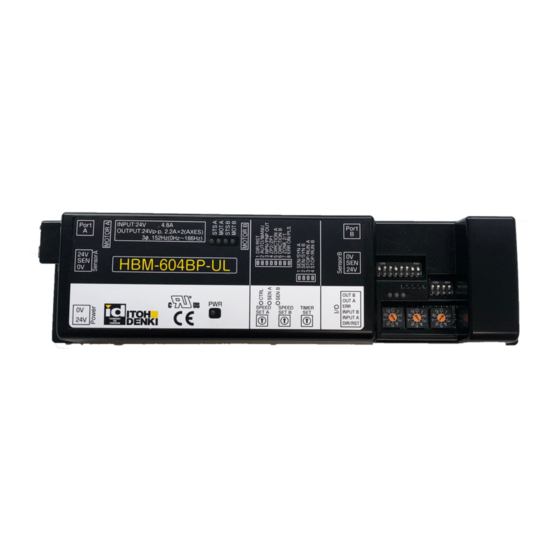
Specifications Dimensions: User Interface: Specifications subject to change without notice 2 Great Valley Blvd., Wilkes-Barre, PA 18706 Office Ph: 570-820-8811 Fax: 570-820-8838 www.itohdenki.com... -
Page 4: Connections
Connections Female Connector for Wiring 2 PIN Connector for Power WAGO #231-302 / 026-000 Description +24V DC ±10% (full-wave rectified, smoothed Wire size: current <10% ripple) 28~14AWG Ordered Separately Female Connector for Wiring 6 PIN Connector for external control WAGO #733-106 Description Direction or error reset (selectable on SW1-1) Motor A forcible run or stop (selectable on SW2-3) - Page 5 Input / Output settings - CN4: CN4-1 – Direction / Error reset (selectable by SW1-1; see page 11) Direction input (SW1-1; OFF) [Default] Reverses the logic flow and motor direction while the input is active. Logic flow is independent of motor direction. This signal is shared through the communication cable.
- Page 6 connections (continued): CN302 & Female Connector for Wiring 8 PIN connector for Communication Cable CN402 RJ-45 Description Error status Error status Motor status Wire size: Motor status 26 AWG Error reset Equivalent 8 wire cable 0V DC Sensor status Sensor status Communication Cable –...
- Page 7 connections (continued): Male Connector on Card Female Connector for Wiring 10 PIN Connector for Motor JST #S10B-XH-A JST #XHP-10 Description GND – Grey +12V DC – Blue Motor phase U – Red Wire size: 28~22AWG Motor phase V – White &...
-
Page 8: Installation Precautions
Installation Precautions IMPORTANT: PLEASE READ BEFORE ISNTALLATION Precaution Action Reason Use a sensor that would have an The HBM responds to the active signal received from active output when the zone is the sensor to denote zone occupation. If the incorrect occupied type is used, the HBM would “think”... - Page 9 Installation Precautions IMPORTANT: PLEASE READ BEFORE ISNTALLATION Precaution Action Reason This completes the signal path from one section of the 0V line of all power supplies on the conveyor (powered by a power supply) to the adjacent Multiple power same conveyor line (powering the section of conveyor (powered by another power supplies card/rollers, &...
-
Page 10: Operation
Operation Input / Output Settings SW1: DIP-SW Function ON Setting OFF Setting Initial Setting Error Reset or Direction input Error reset Direction Error recovery Manual Automatic ON HBM-604BP PNP or NPN output OFF HBM-604BN ZPA release mode Train / Slug Singulated Motor A direction Based on MDR type... - Page 11 Input / Output Settings SW1 (Continued): DIP switch 1-3 – Output signal type for both CN4-5 (OUT A) & CN4-6 (OUT B) PNP (ON) [Default on HBM-604BP] When active the output will be +24V DC Do not connect to a low impedance input, 0V, or GND NPN (OFF) [Default on HBM-604BN] When active the output will be 0V DC DIP switch 1-4 –...
- Page 12 Input / Output Settings SW2: DIP-SW Function ON Setting OFF Setting Initial Setting Sensor A or Motor A synchronous Synchronization signal Sensor signal Sensor B or Motor B synchronous Synchronization signal Sensor signal Motor A input function Forcible run Forcible stop Motor B input function Forcible run Forcible stop...
-
Page 13: Speed Adjustment
Speed adjustment: Rotary switch SW3 – 10 step speed setting for Motor A Used to vary the speed on motor A Rotary switch SW4 – 10 step speed setting for Motor B Used to vary the speed on motor B PM486FE-60 Speed* Rotary Switch... -
Page 14: Timer Settings
timer settings: Rotary switch SW5 – 10 step timer setting for both motors Used to vary timer settings for the run hold timer, sensor timer and jam timer Time (seconds) Rotary Switch (SW5) Run Hold & Sensor Slave mode Sensor Timer: controls the RUN time of the motor during the zone’s infeed operation in the ZPA system Present zone must receive signals through the communication cable from the upstream zone to function Present zone will RUN when... -
Page 15: Other Settings
timer settings (continued): Jam Timer: controls the RUN time of the motor during the zone’s running operation in the ZPA system Jam Timer starts when Present zone is running and its photo-sensor becomes blocked Jam Timer will STOP the present zone when Present zone is running and its photo-sensor remains blocked AND Jam Timer reaches the set time Jam Timer is RESET when... -
Page 16: Led And Error Indications
led and error indications: Specifications subject to change without notice 2 Great Valley Blvd., Wilkes-Barre, PA 18706 Office Ph: 570-820-8811 Fax: 570-820-8838 www.itohdenki.com... - Page 17 LED AND ERROR INDICATIONS (continued): Specifications subject to change without notice 2 Great Valley Blvd., Wilkes-Barre, PA 18706 Office Ph: 570-820-8811 Fax: 570-820-8838 www.itohdenki.com...
- Page 18 LED AND ERROR INDICATIONS (continued): solution: 1. Indicates either a low voltage error or the fuse has blown. First check that there is a stable +24V DC power. If in manual recovery cycle the power to reset a low voltage error, if in automatic recovery the error will reset once a stable +24V DC is reached.
- Page 19 LED AND ERROR INDICATIONS (continued): 5. Back EMF error. See more information under Input/Output Settings, DIP switch 1-2. Roller(s) were driven faster than their designed speed and the HBM-604B activates the dynamic brake to slow the product down. In automatic recovery the card returns to normal operation once the voltage decreased to a safe level.
-
Page 20: Conveyor Zone Configuration
COnveyor zone configuration standard zone: This configuration (factory set) is the standard set-up for any zone that is not specifically an infeed or discharge zone. Review page 3 for default dip switch settings. Specifications subject to change without notice 2 Great Valley Blvd., Wilkes-Barre, PA 18706 Office Ph: 570-820-8811 Fax: 570-820-8838 www.itohdenki.com... -
Page 21: Infeed Zone
infeed zone: The infeed zone can use 2 photo-sensors 1. Main photo-sensor for motor B 2. Infeed photo-sensor (powered separately) Set up • Card is in standard configuration • Distance between the infeed photo-sensor and the main photo-sensor should be set the same distance that is between all the adjacent zone photo-sensors •... -
Page 22: Discharge Zone
discharge zone: The card is in standard orientation Discharge zone is applied when an article is to accumulate once it reaches the last HBM zone. Without a communication cable connected to CN301 in the default direction or CN402 when the direction signal is applied to CN4-1, the card automatically accumulates at the last sensor. -
Page 23: Single Zone One Mdr
single zone, one mdr: The card is in standard orientation Applicable when only one zone and one MDR are needed. Set DIP switch SW1-7 ON for single zone operation. To remove motor B’s motor unplugged error set DIP switch SW2-4 OFF. This configuration is used both with and without external direction signal input to CN4-1. -
Page 24: Single Zone Two Mdrs
single zone, Two mdrs: The card is in standard orientation Applicable when two MDR’s are needed in one zone. Set DIP switch SW1-7 ON for single zone operation. To synchronize motor B with motor A set DIP switch SW2-2 ON. This configuration is used both with and without external direction signal input to CN4-1. - Page 25 Handshake signals between HBM-604BP and IB-E03BP: The cards are in standard orientation An HBM-604B can exchange handshake signals with the IB-E03B and IB-E04F. Product will accumulate at the last zone before the IB card. When sensor A is blocked on the HBM-604B, it sends the sensor out signal to the IB.
-
Page 26: Revision History
REVISION HISTORY Revision Number Change 15-0115 Initial document 15-0528 Updates to page 11 forcible run 19-0107 Updated to -UL and updated address Corrected references in text to CN2 pins to reference CN4 pins. 20-0130 Altered some wordings and images to bring text and images in line with those of HBK-608.
Need help?
Do you have a question about the POWER MOLLER 24 HBM-604BN and is the answer not in the manual?
Questions and answers