
Subscribe to Our Youtube Channel
Related Manuals for Aerotech HexGen HEX150-125HL


Summary of Contents for Aerotech HexGen HEX150-125HL
-
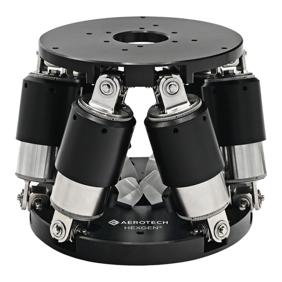
Page 1: Hexgen® Hex150-125Hl Miniature Hexapod Six-Dof Positioning System
HexGen HEX150-125HL Miniature Hexapod Six-DOF ® Positioning System HARDWARE MANUAL Revision 1.00... - Page 2 This manual contains proprietary information and may not be reproduced, disclosed, or used in whole or in part without the express written permission of Aerotech, Inc. Product names mentioned herein are used for identification purposes only and may be trademarks of their respective companies.
-
Page 3: Table Of Contents
Chapter 3: Electrical Specifications and Installation 3.1. Motor and Feedback Connectors 3.2. Machine Direction Chapter 4: Maintenance 4.1. Service and Inspection Schedule 4.2. Cleaning and Lubrication 4.3. Troubleshooting Appendix A: Warranty and Field Service Appendix B: Revision History Index www.aerotech.com... -
Page 4: List Of Figures
Figure 1-1: HEX150-125HL Callouts Figure 1-2: Axis Orientation Figure 2-1: HEX150-125HL Dimensions Figure 2-2: HEX150-125HL Mounting Plate Dimensions Figure 2-3: Mounting Hole Locations Figure 2-4: HEX150-125HL Vertical Load Capabilities Figure 2-5: HEX150-125HL Horizontal Load Capabilities Figure 3-1: Machine Direction www.aerotech.com... -
Page 5: List Of Tables
Hardware Manual HEX150-125HL List of Tables Table 1-1: Model Options Table 1-2: Environmental Specifications Table 1-3: HEX150-125HL Series Specifications Table 2-1: Hexapod to Mounting Surface Hardware Table 4-1: Troubleshooting www.aerotech.com... -
Page 6: Eu Declaration Of Incorporation
HEX150-125HL Hardware Manual EU Declaration of Incorporation Manufacturer Aerotech, Inc. 101 Zeta Drive Pittsburgh, PA 15238-2811 herewith declares that the product: HEX150-125HL hexapod is intended to be incorporated into machinery to constitute machinery covered by the Directive 2006/42/EC as amended; and that the following harmonized European standards have been applied:... -
Page 7: Ukca Declaration Of Incorporation
Hardware Manual HEX150-125HL UKCA Declaration of Incorporation Manufacturer Aerotech, Inc. 101 Zeta Drive Pittsburgh, PA 15238-2811 herewith declares that the product: HEX150-125HL hexapod To which this declaration relates, meets the essential health and safety requirements and is in conformity with the relevant UK Legislation listed below:... -
Page 8: Safety Procedures And Warnings
To find the newest information about this product, refer to www.aerotech.com. If you do not understand the information in this manual, contact Aerotech Global Technical Support. IMPORTANT: This product has been designed for light industrial manufacturing or laboratory environments. -
Page 9: Installation And Operation
Use care when you move the hexapod or you could negatively affect the performance of it. WARNING: Trip Hazard! Route, house, and secure all cables, duct work, air, or water lines. Failure to do so could introduce trip hazards around the system that could result in physical injury or could damage the equipment. www.aerotech.com... -
Page 10: Electrical Warnings
It is the responsibility of the End User/System Integrator to make sure that stages are properly connected and grounded per Engineering Standards and applicable safety requirements. It is the responsibility of the End User/System Integrator to configure the system drive or controller within the Aerotech motor/stage electrical and mechanical specifications. www.aerotech.com... -
Page 11: Motor-Related Warnings
Hardware Manual HEX150-125HL Motor-Related Warnings Aerotech motors are capable of producing high forces and velocities. Obey all warnings and all applicable codes and standards when you operate a system that incorporates Aerotech motors. DANGER: Mechanical Hazard! Personnel must be made aware of the mechanical hazards during set up or when you do service to the stage. -
Page 12: Pinch Points
(during normal operation, for example). when the system is moved manually (during the installation process or when you do maintenance, for example). Motors are capable of very high speeds and acceleration rates. Figure 2: Typical Pinch Point Locations www.aerotech.com... -
Page 13: Handling And Storage
Do not use the cables to lift or move the hexapod. If the hexapod is heavy, a single person lift could cause injury. Use assistance when you lift or move it. Refer to Section 2.1. for dimensions Refer to Section 1.2. for mass specifications. www.aerotech.com... - Page 14 Let the hexapod stabilize at room temperature for at least 12 hours to make sure that all of the align- ments, preloads, and tolerances are the same as they were when they were tested at Aerotech. Remove the shipping brackets before you operate the hexapod. Retain them for future use.
- Page 15 Store the hexapod in the original shipping container. If the original packaging included ESD protective packaging, make sure to store the hexapod in it. The storage location must be dry, free of dust, free of vibrations, and flat. Refer to Section 1.1. Environmental Specifications www.aerotech.com...
- Page 16 HEX150-125HL Hardware Manual This page intentionally left blank. www.aerotech.com...
-
Page 17: Chapter 1: Overview
HEX150-125HL Callouts Table 1-1: Model Options ® HexGen HEX150-125HL Hexapod 6-DOF Positioning System Six degree-of-freedom hexapod positioning system; 150 mm diameter base; 125 HEX150-125HL mm height at mid-travel; high-load capacity version Customization Contact Aerotech for details about additional customization options. www.aerotech.com... -
Page 18: Environmental Specifications
Indoor use only. 1.1.1. Accuracy and Temperature Effects Aerotech products are designed for and built in a 20 °C environment. Moderate temperature changes will affect the accuracy while extreme temperature changes could cause damage to the machine. At a minimum, the environmental temperature must be controlled to within 1 °C per hour to ensure the safety of the hexapod. -
Page 19: Basic Specifications
(1) Travels are mutually-exclusive. Consult the HexGen Hexapod Sizer on the Aerotech website for detailed workspace sizing. (2) Measured with single-axis moves at a height of 50 mm above the moving platform. Results can be payload and workpoint dependent. (3) X, Y, Z performance certified as standard. -
Page 20: Understanding Basic Hex150-125Hl Operation
® workspace. Refer to the HexGen Programming Guide for more information about controlling hexapod section of www.aerotech.com. Select the Manuals motion. To get a copy of this guide, go to the Resources and Help Files tab. Then download Hexapod Programming User Guide from the User Guides category. -
Page 21: Homing
Programming User Guide for more information about how to initialize a hexapod. WARNING: When enabled, each strut will make a small move to perform the commutation search. The motion is variable. Ensure that any fixturing is away from the stage to avoid a crash. www.aerotech.com... - Page 22 HEX150-125HL Hardware Manual This page intentionally left blank. www.aerotech.com...
-
Page 23: Chapter 2: Mechanical Specifications And Installation
All specifications and illustrations are for reference only and were complete and accurate as of the release of this manual. To find the newest information about this product, refer to www.aerotech.com. If you do not understand the information in this manual, contact Aerotech Global Technical Support. www.aerotech.com... -
Page 24: Dimensions
HEX150-125HL Hardware Manual 2.1. Dimensions Figure 2-1: HEX150-125HL Dimensions www.aerotech.com... -
Page 25: Figure 2-2: Hex150-125Hl Mounting Plate Dimensions
Hardware Manual HEX150-125HL Figure 2-2: HEX150-125HL Mounting Plate Dimensions www.aerotech.com... -
Page 26: Securing The Hexapod To The Mounting Surface
IMPORTANT: To maintain accuracy, the mounting surface must be flat to within 0.0127 mm over the contact area. Three M4 mounting screws are required to mount the hexapod to the mounting surface. Refer to Figure 2-3 Section 2.1. Dimensions for mounting locations and Table 2-1 for tightening torque values. www.aerotech.com... -
Page 27: Figure 2-3: Mounting Hole Locations
Refer to Section 2.1. for specific model mounting locations and dimensions. Table 2-1: Hexapod to Mounting Surface Hardware Mounting Hardware Typical Screw Torque M4 or 8-32 SHCS (3 places) 2 N·m Figure 2-3: Mounting Hole Locations www.aerotech.com... -
Page 28: Attaching The Payload To The Hex150-125Hl
Aerotech recommends that customers use a representative payload during start-up to prevent accidental damage to the stage and the payload. Proceed with the electrical installation and test the motion control system in accordance with the system documentation. -
Page 29: Figure 2-5: Hex150-125Hl Horizontal Load Capabilities
Hardware Manual HEX150-125HL Figure 2-5: HEX150-125HL Horizontal Load Capabilities www.aerotech.com... - Page 30 HEX150-125HL Hardware Manual This page intentionally left blank. www.aerotech.com...
-
Page 31: Chapter 3: Electrical Specifications And Installation
Aerotech motion control systems are adjusted at the factory for optimum performance. When the HEX150- 125HL is part of a complete Aerotech motion control system, setup should only require that you connect the hexapod to the appropriate drive chassis with the cables provided. Labels on the system components should indicate the appropriate connections. -
Page 32: Motor And Feedback Connectors
Additional grounding and safety precautions are required for applications requiring access to the stage while it is energized. If the HEX150-125HL is built with standard Aerotech motors and encoders, it will arrive from the factory completely wired and assembled. www.aerotech.com... -
Page 33: Machine Direction
Hardware Manual HEX150-125HL 3.2. Machine Direction Aerotech stages are configured to have positive and negative "machine" directions. The machine direction defines the phasing of the feedback and motor signals and is dictated by the hexapod wiring (refer to Section 0.1. - Page 34 HEX150-125HL Hardware Manual This page intentionally left blank. www.aerotech.com...
-
Page 35: Chapter 4: Maintenance
Monthly inspections should include but not be limited to: Re-tighten loose connectors. Replace or repair damaged cables. Clean the HEX150-125HL and any components and cables as needed. Repair any damage before operating the HEX150-125HL. www.aerotech.com... -
Page 36: Cleaning And Lubrication
The motor is completely non-contact and requires no lubrication. The HEX150-125HL cannot be lubricated in the field. If the stage requires lubrication, it must be returned to Aerotech. Contact Aerotech Global Technical Support for more instructions. 4.3. Troubleshooting Table 4-1:... -
Page 37: Appendix A: Warranty And Field Service
Aerotech makes no warranty that its products are fit for the use or purpose to which they may be put by the buyer, whether or not such use or purpose has been disclosed to Aerotech in specifications or drawings previously or subsequently provided, or whether or not Aerotech’s... - Page 38 On-site Non-Warranty Repair If any Aerotech product cannot be made functional by telephone assistance or purchased replacement parts, and cannot be returned to the Aerotech service center for repair, then the following field service policy applies: Aerotech will provide an on-site Field Service Representative in a reasonable amount of time, provided that the customer issues a valid purchase order to Aerotech covering all transportation and subsistence costs and the prevailing labor cost, including travel time, necessary to complete the repair.
-
Page 39: Appendix B: Revision History
Hardware Manual HEX150-125HL Appendix B: Revision History Revision Description 1.00 New Manual www.aerotech.com... - Page 40 HEX150-125HL Hardware Manual This page intentionally left blank. www.aerotech.com...
-
Page 41: Index
Service and Inspection Schedule Directive 2006/42/EC shims solvents stage Electrical Installation distortion Electrical Warnings Storage EN 60204-1 2010 EN ISO 12100 2010 EU 2015/863 Table of Contents Temperature Effects Handling Horizontal Load Capabilities Humidity Vertical Load Capabilities inspect Vibration www.aerotech.com... - Page 42 Index HEX150-125HL Hardware Manual Warnings Warranty and Field Service www.aerotech.com...
Need help?
Do you have a question about the HexGen HEX150-125HL and is the answer not in the manual?
Questions and answers