
Subscribe to Our Youtube Channel
Related Manuals for Aerotech HexGen HEX150-140HL


Summary of Contents for Aerotech HexGen HEX150-140HL
-
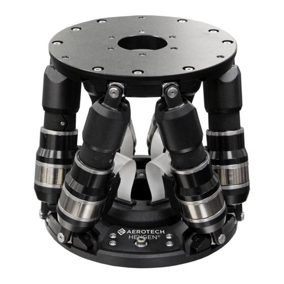
Page 1: Hexgen® Hex150-140Hl Miniature Hexapod Six-Dof Positioning System
HexGen HEX150-140HL Miniature Hexapod ® Six-DOF Positioning System HARDWARE MANUAL Revision 2.00... - Page 2 Global Technical Support Portal for information and support about your Aerotech, Inc. products. The website supplies software, product manuals, Help files, training schedules, and PC-to-PC remote technical support. If necessary, you can complete Product Return (RMA) forms and get information about repairs and spare or replacement parts.
-
Page 3: Table Of Contents
3.2. Motor and Feedback Wiring 3.3. Motor and Feedback Specifications 3.4. Machine Direction 3.5. Feedback Phasing Chapter 4: Maintenance 4.1. Service and Inspection Schedule 4.2. Cleaning and Lubrication 4.3. Troubleshooting Appendix A: Warranty and Field Service Appendix B: Revision History Index www.aerotech.com... -
Page 4: List Of Figures
Axis Orientation Figure 2-1: HEX150-140HL Dimensions Figure 2-2: Mounting Hole Locations Figure 2-3: HEX150-140HL Vertical Load Capabilities Figure 2-4: HEX150-140HL Horizontal Load Capabilities Figure 3-1: Motor and Feedback Wiring Figure 3-2: Machine Direction Figure 3-3: Encoder Phasing Reference Diagram (Standard) www.aerotech.com... -
Page 5: List Of Tables
Table 3-1: Motor and Feedback Connector Pinout Table 3-2: Mating Connector Part Numbers Table 3-3: Encoder Specifications Table 3-4: Limit Switch Specifications Table 3-5: HEX150-140HL Motor Specifications Table 3-6: HEX150-140HL Rotary Encoder Specifications Table 4-1: Grease Specifications Table 4-2: Troubleshooting www.aerotech.com... - Page 6 List of Tables HEX150-140HL Hardware Manual This page intentionally left blank. www.aerotech.com...
-
Page 7: Safety Procedures And Warnings
To find the newest information about this product, refer to www.aerotech.com. If you do not understand the information in this manual, contact Aerotech Global Technical Support. IMPORTANT: This product has been designed for light industrial manufacturing or laboratory environments. - Page 8 Make sure that the product is securely mounted before you operate it. All service and maintenance must be done by approved personnel. WARNING: Securely mount and position all system cables. IMPORTANT: Carefully lift, move, and transport this product. www.aerotech.com...
-
Page 9: Eu Declaration Of Incorporation
HEX150-140HL Hardware Manual EU Declaration of Incorporation EU Declaration of Incorporation Manufacturer: Aerotech, Inc. 101 Zeta Drive Pittsburgh, PA 15238-2811 herewith declares that the product: HEX150-140HL is intended to be incorporated into machinery to constitute machinery covered by the Directive 2006/42/EC as amended;... - Page 10 EU Declaration of Incorporation HEX150-140HL Hardware Manual This page intentionally left blank. www.aerotech.com...
-
Page 11: Chapter 1: Overview
HEX150-140HL Callouts Table 1-1: Model Options ® HexGen HEX150-140HL Hexapod 6-DOF Positioning System Six degree-of-freedom hexapod positioning system; 150 mm diameter base; HEX150-140HL 140 mm height at mid-travel; high-load capacity version Customization Contact Aerotech for details about additional customization options. www.aerotech.com... -
Page 12: Environmental Specifications
Operating: 0 m to 2,000 m (0 ft to 6,562 ft) above sea level Altitude Contact Aerotech if your specific application involves use above 2,000 m or below sea level. Use the system in a low vibration environment. Excessive floor or acoustical Vibration vibration can affect system performance. -
Page 13: Basic Specifications
® 1. Travels are mutually-exclusive. Consult the HexGen Hexapod Sizer on the Aerotech website for detailed workspace sizing. 2. Measured with single-axis moves at a height of 50 mm above the moving platform. Results can be payload and workpoint dependent. -
Page 14: Understanding Basic Hex150-140Hl Operation
To get a copy of this guide, go to the Resources section of www.aerotech.com. Select the Manuals and Help Files tab. Then download Hexapod Programming User Guide from the User Guides category. The six axes include 3 translational axes, X, Y, and Z, and 3 rotational axes, A, B, and C. As shown in the overview, the cables exit out of the back of the base. -
Page 15: Homing
WARNING: When enabled, each strut will make a small move to perform the commutation search. The motion is variable. Ensure that any fixturing is away from the stage to avoid a crash. www.aerotech.com... - Page 16 1.3.3. Homing HEX150-140HL Hardware Manual This page intentionally left blank. www.aerotech.com...
-
Page 17: Chapter 2: Mechanical Specifications And Installation
To find the newest information about this product, refer to www.aerotech.com. If you do not understand the information in this manual, contact Aerotech Global Technical Support. 2.1. Unpacking and Handling the Hexapod If any damage has occurred during shipping, report it immediately. -
Page 18: Dimensions
2.2. Dimensions HEX150-140HL Hardware Manual 2.2. Dimensions Figure 2-1: HEX150-140HL Dimensions www.aerotech.com... -
Page 19: Securing The Hexapod To The Mounting Surface
IMPORTANT: To maintain accuracy, the mounting surface must be flat to within 10 µm per 100 mm. Three M4 mounting screws are required to mount the hexapod to the mounting surface. Refer to Section 2.2. Dimensions Figure 2-2 for mounting locations and Table 2-1 for tightening torque values. www.aerotech.com... -
Page 20: Figure 2-2: Mounting Hole Locations
Refer to Section 2.2. for specific model mounting locations and dimensions. Table 2-1: Stage to Mounting Surface Hardware Mounting Hardware Typical Screw Torque M4 or 8-32 SHCS (3 places) 2 N·m Figure 2-2: Mounting Hole Locations www.aerotech.com... -
Page 21: Attaching The Payload To The Hex150-140Hl
Aerotech recommends that customers use a representative payload during start-up to prevent accidental damage to the stage and the payload. Proceed with the electrical installation and test the motion control system in accordance with the system documentation. -
Page 22: Figure 2-4: Hex150-140Hl Horizontal Load Capabilities
2.4. Attaching the Payload to the HEX150-140HL HEX150-140HL Hardware Manual Figure 2-4: HEX150-140HL Horizontal Load Capabilities www.aerotech.com... -
Page 23: Chapter 3: Electrical Specifications And Installation
Electrical installation requirements will vary depending on product options. Installation instructions in this section are for HEX150-140HL stages equipped with standard Aerotech motors intended for use with an Aerotech motion control system. Contact Aerotech for further information regarding products that are otherwise configured. -
Page 24: Motor And Feedback Connectors
Additional grounding and safety precautions are required for applications requiring access to the stage while it is energized. If the HEX150-140HL is built with standard Aerotech motors and encoders, it will arrive from the factory completely wired and assembled. www.aerotech.com... -
Page 25: Table 3-1: Motor And Feedback Connector Pinout
Reserved Reserved Frame Ground Motor Phase A Motor Phase B Motor Phase C Table 3-2: Mating Connector Part Numbers Mating Connector Aerotech P/N Third Party P/N 25-Socket D-Connector ECK00300 FCI DB25S064TLF Backshell ECK00656 Amphenol 17E-1726-2 www.aerotech.com... -
Page 26: Motor And Feedback Wiring
HEX150-140HL into a completed system. Restrict access to the hexapod when it is connected to a power source. Shielded cables are required for the motor and feedback connections. Figure 3-1: Motor and Feedback Wiring www.aerotech.com... -
Page 27: Motor And Feedback Specifications
Requires external pull-up to +5 V (10 kΩ recommended) Note: If the HEX150-140HL is driven beyond the electrical limit, it will encounter a mechanical stop. Impacting the mechanical stop could cause damage to the stage even at low speeds. www.aerotech.com... -
Page 28: Table 3-5: Hex150-140Hl Motor Specifications
5. All performance and electrical specifications ±10%. 6. Maximum winding temperature is 130 °C 7. Ambient operating temperature range 0 °C - 25 °C; consult Aerotech for performance in elevated ambient temperatures. 8. All Aerotech amplifiers are rated A ; use torque constant in N·m/A when sizing. -
Page 29: Machine Direction
HEX150-140HL Hardware Manual 3.4. Machine Direction 3.4. Machine Direction Aerotech stages are configured to have positive and negative "machine" directions. The machine direction defines the phasing of the feedback and motor signals and is dictated by the hexapod wiring (refer to Section 3.5. -
Page 30: Feedback Phasing
3.5. Feedback Phasing HEX150-140HL Hardware Manual 3.5. Feedback Phasing Motor phase voltage is measured relative to the virtual wye common point. Figure 3-3: Encoder Phasing Reference Diagram (Standard) www.aerotech.com... -
Page 31: Chapter 4: Maintenance
If the application process uses only a small portion of travel for most of the duty cycle, periodically drive the stage through full travel to redistribute the lubrication in the bearings. The motor is completely non-contact and requires no lubrication. www.aerotech.com... -
Page 32: Troubleshooting
Encoder Signal Connection or the Motor Signal Connection: Strut moves Check to make sure that the cable connections are secure. uncontrollably Refer to the Section 3.2. Motor and Feedback Wiring Incorrect Gains: Axes are unstable or squeal Refer to controller documentation www.aerotech.com... -
Page 33: Appendix A: Warranty And Field Service
All Other Repairs - After Aerotech's evaluation, the buyer shall be notified of the repair cost. At such time the buyer must issue a valid purchase order to cover the cost of the repair and freight, or authorize the product(s) to be shipped back as is, at the buyer's expense. - Page 34 Aerotech's approval. On-site Warranty Repair If an Aerotech product cannot be made functional by telephone assistance or by sending and having the customer install replacement parts, and cannot be returned to the Aerotech service center for...
-
Page 35: Appendix B: Revision History
HEX150-140HL Hardware Manual Appendix B: Revision History Appendix B: Revision History Revision Description 2.00 General update 1.00 New Manual www.aerotech.com... - Page 36 Appendix B: Revision History HEX150-140HL Hardware Manual This page intentionally left blank. www.aerotech.com...
-
Page 37: Index
EN 60204-1 2010 S-50 Performance Specifications EN ISO 12100 2010 Securing the hexapod to the Mounting Surface Encoder Specifications serial number EU 2015/863 Service and Inspection Schedule solvents stabilizing stage Handling the Hexapod stage Horizontal Load Capabilities distortion Humidity stabilizing www.aerotech.com... - Page 38 Index HEX150-140HL Hardware Manual Table of Contents Temperature Effects Unpacking and Handling the Hexapod Vertical Load Capabilities Vibration Warranty and Field Service www.aerotech.com...
Need help?
Do you have a question about the HexGen HEX150-140HL and is the answer not in the manual?
Questions and answers