Table of Contents
Advertisement
Quick Links
Advertisement
Table of Contents

Related Manuals for Aerotech HexGen HEX150-140HL


Summary of Contents for Aerotech HexGen HEX150-140HL
-
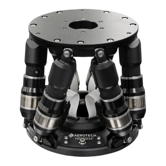
Page 1: Hexgen® Hex150-140Hl Hexapod Hardware Manual
® HexGen HEX150-140HL Hexapod Hardware Manual Revision: 1.00.00... - Page 2 Software Activation: The following link provides information and resources to activate your Aerotech software. Link: Software Activation Manuals, Help Files, and Cable Drawings: Browse a directory of manuals, help files, and cable drawings for Aerotech software and hardware products. Link: Browse Manuals, Help Files, and Cable Drawings Frequently Asked Questions: The Frequently Asked Questions (FAQs) section provides answers to most common questions about Aerotech products.
-
Page 3: Table Of Contents
3.2. Motor and Feedback Wiring 3.3. Motor and Feedback Specifications 3.4. Machine Direction 3.5. Motor and Feedback Phasing Chapter 4: Maintenance 4.1. Service and Inspection Schedule 4.2. Cleaning and Lubrication 4.3. Troubleshooting Appendix A: Warranty and Field Service Appendix B: Revision History Index www.aerotech.com... -
Page 4: List Of Figures
Axis Orientation Figure 2-1: HEX150-140HL Dimensions Figure 2-2: Mounting Hole Locations Figure 2-3: HEX150-140HL Vertical Load Capabilities Figure 2-4: HEX150-140HL Horizontal Load Capabilities Figure 3-1: Motor and Feedback Wiring Figure 3-2: Machine Direction Figure 3-3: Encoder Phasing Reference Diagram (Standard) www.aerotech.com... -
Page 5: List Of Tables
Environmental Specifications Table 1-3: HEX150-140HL Series Specifications Table 2-1: Stage to Mounting Surface Hardware Table 3-1: Motor and Feedback Pinout Table 3-2: Feedback Specifications Table 3-3: HEX150-140HL Motor Specifications Table 3-4: HEX150-140HL Rotary Encoder Specifications Table 4-1: Grease Specifications www.aerotech.com... -
Page 6: Safety Procedures And Warnings
Read this manual in its entirety before installing, operating, or servicing this product. If you do not understand the information contained herein, contact an Aerotech representative before proceeding. Strictly adhere to the statements given in this section and other handling, use, and operational information given throughout the manual to avoid injury to you and damage to the equipment. -
Page 7: Eu Declaration Of Incorporation
Directive(s): 2011/65/EU RoHS 2 Directive EU 2015/863 Amendment RoHS 3 Directive Authorized Representative: / Simon Smith, European Director Aerotech Ltd The Old Brick Kiln, Ramsdell, Tadley Hampshire RG26 5PR Engineer Verifying Compliance / Alex Weibel 101 Zeta Drive... - Page 8 EU Declaration of Incorporation HEX150-140HL Hardware Manual This page intentionally left blank. www.aerotech.com...
-
Page 9: Chapter 1: Overview
Chapter 1: Overview Chapter 1: Overview N O T E : Aerotech continually improves its product offerings; listed options may be superseded at any time. All drawings and illustrations are for reference only and were complete and accurate as of this manual’s release. -
Page 10: Environmental Specifications
Indoor use only 1.1.1. Accuracy and Temperature Effects Aerotech products are designed for and built in a 20°C environment. Moderate temperature changes will affect the accuracy while extreme temperature changes could cause damage to the machine. At a minimum, the environmental temperature must be controlled to within 1°C per hour to ensure the safety of the hexapod. -
Page 11: Basic Specifications
® 1. Travels are mutually-exclusive. Consult the HexGen Hexapod Sizer on the Aerotech website for detailed workspace sizing. 2. Measured with single-axis moves at a height of 50 mm above the moving platform. Results can be payload and workpoint dependent. -
Page 12: Understanding Basic Hex150-140Hl Operation
Programming Guide for more information about controlling hexapod motion. To get a copy of this guide, go to the Manuals, Help files, & Cable Drawings section of www.aerotech.com. Select the Controllers tab. Then download User Guide for Hexapod Programming. The six axes include 3 translational axes, X, Y, and Z, and 3 rotational axes, A, B, and C. As shown in the overview, the cables exit out of the back of the base. -
Page 13: Strut Limits And Hexapod Range
W A R N I N G : When enabled, each strut will make a small move to perform the commutation search. The motion is variable. Ensure that any fixturing is away from the stage to avoid a crash. www.aerotech.com... - Page 14 1.3.3. Homing HEX150-140HL Hardware Manual This page intentionally left blank. www.aerotech.com...
-
Page 15: Chapter 2: Mechanical Specifications And Installation
Allowing it to stabilize to room temperature will ensure that all of the alignments, preloads, and tolerances are the same as they were when tested at Aerotech. Use compressed nitrogen or clean, dry, oil-free air to remove any dust or debris that has collected during shipping. -
Page 16: Dimensions
2.2. Dimensions HEX150-140HL Hardware Manual 2.2. Dimensions Figure 2-1: HEX150-140HL Dimensions www.aerotech.com... -
Page 17: Securing The Hexapod To The Mounting Surface
Three M4 mounting screws are required to mount the hexapod to the mounting surface. Refer to Figure 2- Section 2.2. Dimensions for mounting locations and Table 2-1 for tightening torque values. www.aerotech.com... -
Page 18: Figure 2-2: Mounting Hole Locations
Refer to Section 2.2. for specific model mounting locations and dimensions. Table 2-1: Stage to Mounting Surface Hardware Mounting Hardware Typical Screw Torque M4 or 8-32 SHCS (3 places) 2 N·m Figure 2-2: Mounting Hole Locations www.aerotech.com... -
Page 19: Attaching The Payload To The Hex150-140Hl
Aerotech recommends that customers use a representative payload during start-up to prevent accidental damage to the stage and the payload. Proceed with the electrical installation and test the motion control system in accordance with the system documentation. -
Page 20: Figure 2-4: Hex150-140Hl Horizontal Load Capabilities
2.4. Attaching the Payload to the HEX150-140HL HEX150-140HL Hardware Manual Figure 2-4: HEX150-140HL Horizontal Load Capabilities www.aerotech.com... -
Page 21: Chapter 3: Electrical Specifications And Installation
Electrical installation requirements will vary depending on product options. Installation instructions in this section are for HEX150-140HL stages equipped with standard Aerotech motors intended for use with an Aerotech motion control system. Contact Aerotech for further information regarding products that are otherwise configured. -
Page 22: Motor And Feedback Connectors
N O T E : Refer to the other documentation accompanying your Aerotech equipment. Call your Aerotech representative if there are any questions on system configuration. N O T E : If using standard Aerotech motors and cables, motor and encoder connection adjustments are not required. -
Page 23: Table 3-1: Motor And Feedback Pinout
+5 V supply input for feedback devices Reserved Positive (CW) hardware limit Reserved Reserved Frame Motor Phase A Motor Phase B Motor Phase C Mating Connector Aerotech P/N Third Party P/N Backshell ECK00656 Amphenol 17E-1726-2 Connector ECK00300 FCI DB25S064TLF www.aerotech.com... -
Page 24: Motor And Feedback Wiring
All motor and controller manufacturers have their own designations for motor phases A/B/C and Hall signals A/B/C (refer to Section 3.5. for motor phasing). Shielded cables are required for the motor and feedback connections. Figure 3-1: Motor and Feedback Wiring www.aerotech.com... -
Page 25: Motor And Feedback Specifications
Requires external pull-up to +5 V (10 kΩ recommended) Notes: If the HEX150-140HL is driven beyond the electrical limit, it will encounter a mechanical stop. Impacting the mechanical stop could cause damage to the stage even at low speeds. www.aerotech.com... -
Page 26: Table 3-3: Hex150-140Hl Motor Specifications
5. All performance and electrical specifications ±10% 6. Maximum winding temperature is 130 °C 7. Ambient operating temperature range 0 °C - 25 °C; consult Aerotech for performance in elevated ambient temperatures 8. All Aerotech amplifiers are rated A ; use torque constant in N·m/A... -
Page 27: Machine Direction
HEX150-140HL Hardware Manual 3.4. Machine Direction 3.4. Machine Direction Aerotech stages are configured to have positive and negative "machine" directions. The machine direction defines the phasing of the feedback and motor signals and is dictated by the stage wiring (refer to Section 3.5. -
Page 28: Motor And Feedback Phasing
3.5. Motor and Feedback Phasing HEX150-140HL Hardware Manual 3.5. Motor and Feedback Phasing Motor phase voltage is measured relative to the virtual wye common point. Figure 3-3: Encoder Phasing Reference Diagram (Standard) www.aerotech.com... -
Page 29: Chapter 4: Maintenance
Monthly inspections should include but not be limited to: Re-tighten loose connectors. Replace or repair damaged cables. Clean the HEX150-140HL and any components and cables as needed. Repair any damage before operating the HEX150-140HL. www.aerotech.com... -
Page 30: Cleaning And Lubrication
If the application process uses only a small portion of travel for most of the duty cycle, periodically drive the stage through full travel to redistribute the lubrication in the bearings. The motor is completely non-contact and requires no lubrication. www.aerotech.com... -
Page 31: Troubleshooting
Encoder Signal Connection or the Motor Signal Connection: Strut moves Check to make sure that the cable connections are secure. uncontrollably Refer to the Section 3.2. Motor and Feedback Wiring Axes are unstable or Incorrect Gains: squeal Refer to controller documentation www.aerotech.com... - Page 32 4.3. Troubleshooting HEX150-140HL Hardware Manual This page intentionally left blank. www.aerotech.com...
-
Page 33: Appendix A: Warranty And Field Service
All Other Repairs - After Aerotech's evaluation, the buyer shall be notified of the repair cost. At such time the buyer must issue a valid purchase order to cover the cost of the repair and freight, or authorize the product(s) to be shipped back as is, at the buyer's expense. - Page 34 Aerotech's approval. On-site Warranty Repair If an Aerotech product cannot be made functional by telephone assistance or by sending and having the customer install replacement parts, and cannot be returned to the Aerotech service center for repair, and if Aerotech determines the problem could be warranty-related, then the following policy applies:...
-
Page 35: Appendix B: Revision History
HEX150-140HL Hardware Manual Appendix B: Revision History Appendix B: Revision History Revision Description 1.00.00 New Manual www.aerotech.com... - Page 36 Appendix B: Revision History HEX150-140HL Hardware Manual This page intentionally left blank. www.aerotech.com...
-
Page 37: Index
EN ISO 12100 2010 Electrical Specifications Encoder Specifications S-50 Performance Specifications serial number Global Technical Support Serial Output Encoder Service and Inspection Schedule Horizontal Load Capabilities shimming Humidity solvents stabilizing stage Incremental Encoder stage inspect distortion Inspection Schedule stabilizing www.aerotech.com... - Page 38 Index HEX150-140HL Hardware Manual Support Technical Support Vertical Load Capabilities Vibration Warranty and Field Service www.aerotech.com...
Need help?
Do you have a question about the HexGen HEX150-140HL and is the answer not in the manual?
Questions and answers