Table of Contents
Advertisement
Quick Links
Advertisement
Table of Contents

Related Manuals for PIAB MFE.050H Series


Summary of Contents for PIAB MFE.050H Series
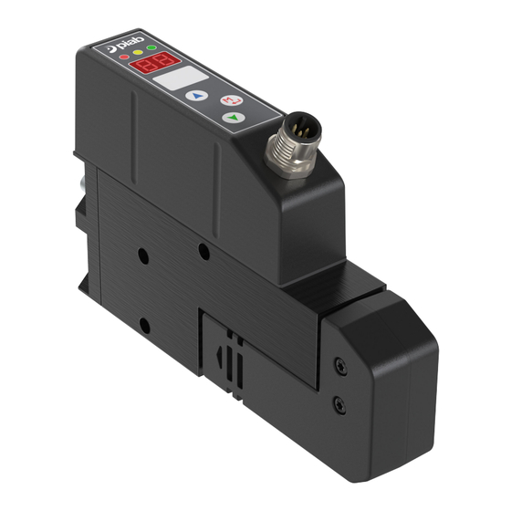
- Page 1 Multi Function Ejector...
- Page 2 This manual is available in the following languages at piab.com The original manual is written in English. English Français Deutsch Italiano Polski Português (Brasil) Русский Español Svenska Copyright © 2024 Piab AB Specifications subject to change without notice.
-
Page 3: Table Of Contents
Table of Contents 1. Introduction to the manual ......................4 1.1. About the manual ......................... 4 1.2. Safety signs used in the manual ................... 4 1.2.1. Warning signs ......................4 1.2.2. Mandatory signs ......................4 1.3. Target group ......................... 5 1.4. -
Page 4: Introduction To The Manual
1. Introduction to the manual 1.1. About the manual The manual is available for download at piab.com in the languages shown on page 2. The original instruc- tions are written in English. • The responsible party for the production site must ensure that this manual will be read and understood. -
Page 5: Target Group
Introduction to the manual Important Wear ear protection 1.3. Target group This manual, especially the section about safety, shall be read by all staff who will perform any type of work with the product or equipment: • Installation personnel • Operating personnel •... -
Page 6: Safety Instruction
2. Safety instruction 2.1. Disclaimer Piab AB is not responsible for installation and operation of MFE on a robot system. The required steps must be undertaken in supervision and approval by authorized system integrators. The product is intended to be incorporated into machinery or to be assembled with other machinery to constitute machinery covered by Directive 2006/42/EC, as amended. -
Page 7: Assembly
Safety instruction Warning • Do not evacuate liquids to avoid product damage and application failure. • Ensure that a filter is used for preventing ejected objects if the product is used for evacuating solid content. • Ensure no foreign matters enter the exhaust port due to the risk of ejected objects and damage of the product. -
Page 8: Misuse
Safety instruction 2.5. Misuse • Do not use the product if it is damaged. • The product shall not be used to create vacuum or blow for other purposes than the intended use. • Do not use the product for evacuating liquids. •... -
Page 9: Introduction To The Mfe
SWEDEN 3.2. Identification label Each unit is identified by a label with identification information. For any communication with Piab AB or service centers always refer to the label information and state both the Product code and Serial number. 3.3. Overview The ejector is available with both integrated silencer and G1/2"... -
Page 10: Technical Data
Introduction to the MFE 3.4. Technical data Description Symbol Min. Typ. Max. Unit Comment Supply voltage 19.2 26.4 Reverse polarity prot. Rated current from V = 24V Voltage output signals Current output signals Short circuit prot. Voltage input signals Relative to V Current input signals = 24V Storage temperature... -
Page 11: Choose The Right Size Pipe And Tube
Introduction to the MFE 3.7. Choose the right size pipe and tube Ejector size Air supply On the vacuum side On the exhaust side Designation Air con- sump- tion in Nl/min Internal diameter Internal diameter Internal diameter (mm) (mm) (mm) MFE.050H.xxx MFE.100H.xxx MFE.200H.xxx... -
Page 12: Installation
Installation 4. Installation 4.1. Multiple manifolds for MFE • Compact block mounting • For all MFE sizes • Excellent overview • Easy exchange of units • Easy installation • To prepare for a potential increase in the number of ejectors on the multiple manifolds, a blind plate is available to reserve one position for this purpose. - Page 13 Installation 1 = Compressed air, 2 = Vacuum Multiple mani- A mm ["] B mm ["] Vacuum - connec- Weight kg [lb] Order no. fold for MFE tion (2) 76 [3] 63 [2.5] G 3/8 (x2) 0.325 [0.717] 0244553* 102 [4] 89 [3.5] G 3/8"...
-
Page 14: Function Mfe - Nc
Installation 4.2. Function MFE - NC Solenoid valve (NC) for air supply. Activated only when the vacuum level is too low. Makes considerable air savings possible. Solenoid valve for blow-off. For a quick and accurate blow-off. Built-in Vacuum sensor. Vacuum safety valve. Maintains the vacuum level when the ejector is not activated. Adjustable blow-off. -
Page 15: Mfe Ejector Programming
Installation 4.4. MFE ejector programming Function "AUTOVAC" (Selected with Parameter U) Standard case • Vacuum generation starts on input signal from an external system (+24V). • As long as this signal is active, the ejector will maintain the vacuum levels automatically. For example: When the vacuum level is less than 65 -kPa (parameter C) vacuum is generated, and when reaching more than 70 -kPa (parameter E) the vacuum generation is stopped in order to save as much compressed air as possible. -
Page 16: Potential Energy Savings And Control Of Mfe
Installation Feedback "Predictive maintenance" for AUTOVAC, version C, S, and R: For Predictive maintenance there is an additional output signal available for the external system (PNP, +24V). This signal can have different behaviors depending on parameter L: 1. A signal while vacuum is generated. Time to reach e.g. 60 (parameter A) can then be measured. Also, if a "re-fill"... -
Page 17: Surveillance
Installation As the vacuum safety valve is maintaining the vacuum level, the solenoid valve for blow-off has to be activated to release the object rapidly and with accuracy. Notice When selecting the MANUVAC function no air saving is available. 4.5.1. Surveillance By adding a surveillance system it is possible to monitor the air tightness of the system. -
Page 18: Operation
Operation 5. Operation 5.1. Connectors Version C, Version D, Version S, Version R, M8 M12 5-pin M12 5-pin M12 8-pin 8-pin** Time set blow-off Adaptive blow-off Manual / External blow-off Feedback, Vacuum OK / Blow-off OK Feedback, Predictive Mainte- nance* * Feedback when deviations in vacuum generation, e.g. - Page 19 Operation M12 male connector, AVAC Ver. S Pin 1- Vacuum/blow-off OK Output +24VDC Pin 2 - Supply voltage +24 VDC Pin 3 - Predictive Maintenance Output +24 VDC Pin 4 - Vacuum (Start) Input 24 VDC PNP Pin 5 - Pin 6 - Blow-off on Input 24 VDC PNP Pin 7 - Supply voltage...
- Page 20 Operation Vacuum Level Input: Start Vacuum Level Output signal: Vacuum/ blow-off OK Vacuum Level Output signal: "Predictive maintenance" option 1 Vacuum level Output signal: "Predictive maintenance" option 2 Vacuum Level Input: Blow-off on x: time, y: -kPa Page 20 of 36...
-
Page 21: Parameter Settings
Operation 5.2. Parameter settings Parameter Parameter Parameter description name (Visible in value display) Vacuum level OK limit (default: 60 -kPa). AUTOVAC and MANUVAC. Lower breakpoint (default: 65 -kPa). AUTOVAC. Upper breakpoint (default: 70 -kPa). AUTOVAC. Blow-off time (default: 500 ms. 100 ms / step). Limit value for number of vacuum cycles (default: 2 pcs). - Page 22 Operation Parameter name (Visible Parameter description in display) 60: Limit for "Vacuum level OK" feedback (default: 60 -kPa) When vacuum generation has reached this limit, a signal is given to the exter- nal system. This parameter value has to be lower than parameter C. Vacuum level Input: Start...
- Page 23 Operation Parameter name (Visible Parameter description in display) 70: Limit for vacuum generation OFF (default: 70 -kPa) When vacuum level is above this value, vacuum generation stops. This parame- ter value has to be greater than parameter C. Vacuum level Input: Start x: time y: -kPa...
- Page 24 Operation Parameter name (Visible Parameter description in display) 2: Limit for number of "Re-fills", AUTOVAC (default: 2 times). Valid only for versions D, S, and R when parameter L = 2. *Number of "Re-fills" (default 2 times) **Signal when the limit for "Re-fills"...
- Page 25 Operation Parameter name (Visible Parameter description in display) 1: Predictive Maintenance Feedback Mode (default: 1) Valid only for versions C, S, and R when: MANUVAC: L = 1 (option 1) AUTOVAC: L = 1 (option 1) or L = 2 (option 2) 1: Output for Predic- tive maintenance op- tion 1...
- Page 26 Operation Parameter name (Visible Parameter description in display) 0: Module Save, AUTOVAC (default: 0. 0 = OFF, 1...99 = ON) The purpose of this function is to minimize extensive valve switching caused by e.g. worn/damaged suction cups. If the module has reached a number of "re-fillings"...
-
Page 27: Manual Operation Of The Ejector During Testing And Start Up
Operation Parameter name (Visible Parameter description in display) AUTOVAC function with: • Adaptive time and vacuum manage blow-off (U = 11) • Time operated blow-off (U = 12) • Externally operated blow-off (U = 13). Available only for version D, S, and R MANUVAC function with: •... -
Page 28: Led Indications
Operation In manual operation mode the Arrow button corresponds to Start input signal. Manual operation is obtained by pressing and holding the button during ejector power-up (power only + 24 VDC / GND needed). In manual operation mode the Arrow button corresponds to Blow-off input signal. -
Page 29: Service And Maintenance
Service and maintenance 6. Service and maintenance • Always remember to disconnect the power supply when cleaning or servicing the product. • Make sure all components in the vacuum system are without electricity, compressed air and vacuum be- fore service/repair is done. Disconnect electricity / compressed air / vacuum supply and blow compressed air into the vacuum safety valves so that no vacuum remains. -
Page 30: Troubleshooting
Troubleshooting 7. Troubleshooting Fault Check Action Display lit but no vacuum genera- Check air supply Pressurize ejector tion Check air supply pressure Correct Check the vacuum port fittings, If necessary replace failing compo- Display lit but limited vacuum gen- pipes, suction cups etc. for leakage nent/components. -
Page 31: Recycling And Disposal
Recycling and disposal 8. Recycling and disposal Environmental aspects are considered in the development process of Piab’s products to make sure that a minimal environmental footprint is used. Piab is certified with ISO-14001. Piab also complies with: • RoHS (2002/95/EC) •... -
Page 32: Warranty
Warranty 9. Warranty The Seller gives its Customers a five-year warranty from the receipt of the Products for vacuum pump Prod- ucts (excluding vacuum pumps with electronics/controls, electro-mechanical vacuum pumps, accessories, and controls). The Seller gives its Customers a one-year warranty from the receipt of the Products for all other Products (i.e. - Page 36 +33 (0)16-430 82 67 +33 (0)16-430 82 67 +46 (0)8-630 25 00 +46 (0)8-630 25 00 +55 (0)11-449 290 50 +55 (0)11-449 290 50 +86 21 5237 6545 +86 21 5237 6545 info-france@piab.com info-france@piab.com info-sweden@piab.com info-sweden@piab.com info-brasil@piab.com info-brasil@piab.com info-china@piab.com info-china@piab.com...
Need help?
Do you have a question about the MFE.050H Series and is the answer not in the manual?
Questions and answers