Advertisement
Advertisement
Table of Contents

Related Manuals for PIAB KVG60 Series


Summary of Contents for PIAB KVG60 Series
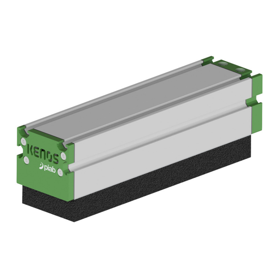
- Page 1 MANUAL KVG60 Series...
-
Page 2: Table Of Contents
KVG60 Series CONTENTS Overview....................3 Work cycle details ................5 Installation................... 8 Parts diagram ..................9 Maintenance ..................11 Problems/solutions................15 Accessories ..................16 Technical data ................... 17 Pneumatic diagrams ................. 19 Safety instructions ................22 Warranties ..................23... -
Page 3: Overview
KVG60 Series Overview Part list single ejector version Pos. Description Connection G 1/8” compressed air (1a) Connection G 1/8” blow-off or vacuum monitoring (1b) Inline ejector exhaust, DO NOT COVER. The aspirated air escapes from the exhaust cover through the written Kenos... - Page 4 KVG60 Series Part list double ejector version Pos. Description Connection G 1/8” compressed air (1a) Connection G 1/8” blow-off or vacuum monitoring (1b) Ejector exhaust, DO NOT COVER. The aspirated air escapes from the two exhaust slots. Part list BL version Pos.
-
Page 5: Work Cycle Details
KVG60 Series Work cycle details The working cycle for a KVG gripping module follows the different technologies involved: Check valve balls version(CVL/CVM/CVH): Positioning the module at the object to handle with the grip pad parallel to the grip surface. Lowering of module until contact with the grip surface... - Page 6 KVG60 Series Check valve piSAVE sense 02/60 (CV19): Positioning the module at the object to handle with the grip pad parallel to the grip surface. Lowering of module until contact with the grip surface Sequential activation of vacuum if multiple modules are present...
- Page 7 KVG60 Series Flow reduction (FR5/FR6/FR8/FR10): Positioning the module at the object to handle with the grip pad parallel to the grip surface. Lowering of module until contact with the grip surface. For fast cycle, we suggest to activate vacuum before module is in contact with the object.
-
Page 8: Installation
KVG60 Series Installation Mounting on the handling system The gripping system is secured with the aid of slot nuts. Special slots for these nuts are available in the basic body. The gripper can be mounted either directly, via robot flange or via spring mountings. -
Page 9: Parts Diagram
KVG60 Series Parts diagram Basic body is an extruded aluminum Pos. Description section and is available in different Basic body lengths. Supply cover Supply/exhaust cover are made of aluminum properly finished. Supply cover seal Technical foam is made of EPDM COAX®... - Page 10 KVG60 Series Ejector body Pos. Description Cover screws Supply cover COAX cartridge ® COAX cartridge ® Posterior housing Anterior housing Tie-beam Tie-beam closing nut Tie-beam cover Supply cover seal O-ring Blind Cartridge for Midi COAX ® Flat washer Specifications subject to change without notice...
-
Page 11: Maintenance
KVG60 Series Maintenance Ejector maintenance For the maintenance of the push in ejector follow these steps: ► Loosen A cover screws of the supply cover and extract the complex B+C. ► Blow and clean the ejectors with compressed air. Verify that the cartridge is intact and there are no breakages. - Page 12 KVG60 Series Check valves maintenance Pos. Description Check valves module Fixing screws check valves module Technical foam Exhaust cover Cover screws Maintenance To access the check valves module, for cleaning, follow these steps with the foam upwards to avoid the spheres spilling during operation: ►...
- Page 13 KVG60 Series Foam maintenance The foam that builds the gripping surface can be damaged during normal use. The average lifetime depends on many factors: nature of the handled objects, quality of the gripping surface, work conditions, cycle times, etc. Foam Change ►...
- Page 14 KVG60 Series Maintenance plan Every 12 Every 6 Daily Weekly Monthly months months Check Max vacuum level of the ejector • Check the vacuum (BL version) • Check the check valves / FR • Check the silencer • Check tightenings •...
-
Page 15: Problems/Solutions
KVG60 Series Problems/solutions Problem Possible reason Solutions Operating pressure too low Increase the pressure Internal diameter of pressure Use hoses with larger internal hose too small diameter Insufficient vacuum level Check and replace if Damaged sealing or vacuum achieved too... -
Page 16: Accessories
KVG60 Series Accessories T-slot nut kits: Art. No Description 0209858 T-slot nut kit 11073-M6-U8-4pcs 0209854 T-slot nut kit 11072-M5-U8-4pcs 0209851 T-slot nut kit 11071-M4-U8-4pcs 0209860 T-slot nut kit 11074-M8-U8-4pcs Kit Flange: Art. No Description 0210847 KIT-FL-FX-KVG60-50-U8 Specifications subject to change without notice... -
Page 17: Technical Data
KVG60 Series Technical data Type Air consumption at 6 bar (NI/s)/ 87.0 psi (scfm) KVG.XXX.60.XXXX.CVX.S1.XX.XX 1.75 /3.71 KVG.XXX.60.XXXX.CVX.S2.XX.XX 3.5 / 7.42 KVG.XXX.60.XXXX.CVX.S4.XX.XX 7.0 / 14.84 Pneumatic technical information COAX® Unit Si32-3 Si MIDI-cartridge Description (1-4 nozzles) Feed pressure, optimal MPa [psi] 0.6 [87]... -
Page 18: Pneumatic Diagrams
KVG60 Series Pneumatic diagram EJ version Optional Optional Only for Only for foam with foam with filter version filter version 1a = Pressure air supply for vacuum 1b = Pressure air supply for blow off 2 = Vacuum 3 = Exhaust... - Page 19 KVG60 Series Spare parts Art. No Description 0107053 COAX cartridge MIDI Si32-3 ® Art. No Description Spare part kit KVG60 0210928 A Silencer KVG60-50 B Exhaust cover seal KVG60-50 C Supply cover seal KVG60-50 D O-ring NBR 29x2.5 (EJ) E O-ring NBR 22x2 (BL)
- Page 20 KVG60 Series Foam spare parts There are four different types of foam spare part types available; Step1, Step 2, Step 3 and Step 6. If you are unsure which type you have please check the part code of your configured KVG product, the first part of the code is the foam spare part code, when you put “FOAM”...
- Page 21 KVG60 Series Safety instructions General safety instructions The correct use of pneumatic equipment within a system is the responsibility of the system designer or the person who determines its technical specifications. The use of safety guards is recommended to minimise the risk of injury to persons; pay close attention to the fact that compressed air may lead to the explosion of closed containers, and vacuum may lead to the implosion of closed containers.
-
Page 22: Safety Instructions
KVG60 Series Assembly Compressed air may be dangerous if used by unskilled personnel. Assembling, using and maintaining systems should solely be carried out by experienced and specially trained per- sonnel. Both for fastening and supplying, solely use the bores and methods provided by the manufacturer. -
Page 23: Warranties
KVG60 Series Warranties The Seller gives its Customers a five-year warranty from the receipt of the Products for vacuum pump Products (excluding electro mechanical vacuum pumps, accessories, controls and Kenos products). • The Seller gives its Customers a one-year warranty from the receipt of the Products for allother Products (i.e. - Page 24 Piab gives you service all over the world. To fi nd your local distributor, please visit www.piab.com No need to compromise www.piab.com...
Need help?
Do you have a question about the KVG60 Series and is the answer not in the manual?
Questions and answers