
Subscribe to Our Youtube Channel
Related Manuals for Rabe COMBIBIRD CB


Summary of Contents for Rabe COMBIBIRD CB
- Page 1 OPERATOR'S MANUAL (ORIGINAL INSTRUCTIONS) Machine number COMBIBIRD CB Two-part folding semi-mounted trailed version...
- Page 3 MOunteD versiOn COMBIBIRD CB quick start Field adjustment Preparing the tractor Check the pressure of the tyres. When working, the implement must be level at the desired speed and depth. - It must be identical on each side of the tractor, both at the front and back.
-
Page 4: Table Of Contents
COmBIBIrD CB peratOr s manual fOlDIng semI mOunteD versIOn able of conTenTs INTRODUCTION Instructions ..........5 Hydraulic and pneumatic connections .... 24 Product documentation ........5 Required hydraulic control valves .......24 Explanation of symbols ........5 Hydraulic pressure ...........24 Regulations and legal provisions ......5 Hydraulic connections ........24... -
Page 5: Instructions
COmBIBIrD CB peratOr s manual fOlDIng semI mOunteD versIOn INTRODUCTION Legend Place and date of reception Implement serial number Make nsTrucTIons Name of manufacturer Address and country of manufacture Permissible maximum weight Allowable imposed mass on tractor coupling Product documentation... -
Page 6: Safety Instructions And Rules
COmBIBIrD CB peratOr s manual fOlDIng semI mOunteD versIOn sufficiently firm to ensure that the implement is perfectly stable afeTy InsTrucTIons and during storage. rules ∙ If your implement is parked, make sure that it is stable to avoid the possibility of physical injury or material damage. - Page 7 COmBIBIrD CB peratOr s manual fOlDIng semI mOunteD versIOn ∙ Correctly use the implement and its controls, do not let ∙ Observe all the common sense rules when driving, especially untrained persons attempt to operate it. in bends in the road and where it is narrow.
- Page 8 COmBIBIrD CB peratOr s manual fOlDIng semI mOunteD versIOn 2.1.10 Safety stickers CAUTION: IMPORTANT: Take care not to damage the safety stickers when Replace damaged or missing stickers. washing the implement. Locations of the safety stickers. UI 1863 UI 1860...
- Page 9 COmBIBIrD CB peratOr s manual fOlDIng semI mOunteD versIOn Explanation of stickers Number Sticker Description Number Sticker Description Stop engine and remove the key Pivoting zone Stop the engine and remove the Remain outside the pivoting zone. ignition key before any maintenance or repair work.
-
Page 10: Use
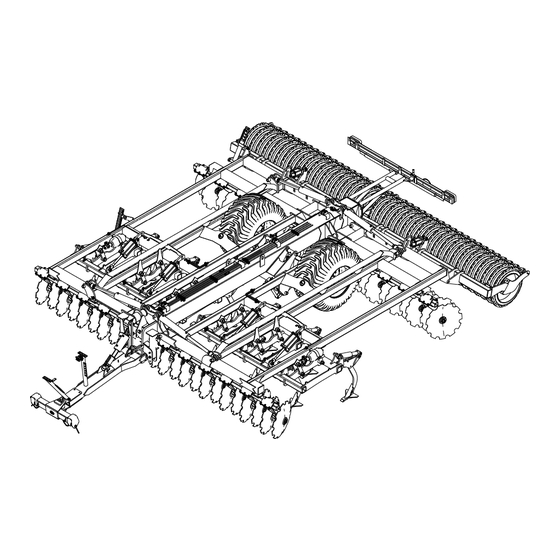
The ImplemenT General views E.g. Combibird CB 6.00 m folding semi-mounted version with kompressor roller Legend Kompressor rear roller Ø 650 mm Cat II-III attachment on arm Undercarriage Adjustable draw bar tie-rod... -
Page 11: Technical Specifications
COmBIBIrD CB peratOr s manual fOlDIng semI mOunteD versIOn Technical specifications Part Standard equipment Optional equipment Hitch ∙ Coupling on lift arm cat. II and III. ∙ Coupling on lift arm cat. IV. ∙ Forged ball joint Ø 55 mm. -
Page 12: Transporting By Truck
COmBIBIrD CB peratOr s manual fOlDIng semI mOunteD versIOn Transporting by truck Adjustable draw bar tie-rod Legend Compensating cylinder Elastomer shock absorber The adjustable stop of the compensating cylinder (1) is used for Legend levelling the implement in the longitudinal (front/rear) direction. -
Page 13: Combined Harrow With Independent Discs And Tines
COmBIBIrD CB peratOr s manual fOlDIng semI mOunteD versIOn Combined harrow with independent discs and tines Combined harrow with independent discs and tines with wheels between the tines and the rear disc gang. Legend Wheels between the rear disc gang and the tines... -
Page 14: Discs
COmBIBIrD CB peratOr s manual fOlDIng semI mOunteD versIOn 3.8.3 Disc assembly with safety spring Discs 3.8.1 Roll"coup disc Legend Safety spring The safety spring enables the discs to follow any type of ground Legend profile. Roll"Coup disc The machine is equipped as standard with the Ø 630 mm, 7 mm Tine thick, notched, Roll"Coup disc. -
Page 15: Deflector (Optional)
COmBIBIrD CB peratOr s manual fOlDIng semI mOunteD versIOn 3.9.1 Non-stop hydraulic safety system (optional) 3.11 Rear-mounted equipment (optional) 3.11.1 Crumbling roller Legend Tine Hydraulic cylinder Legend A hydraulic cylinder (2) is located above each tine (1) Crumbling roller (3). The cylinders of all the tines are connected to the same hydraulic circuit also including an accumulator and a manometer The Ø... - Page 16 COmBIBIrD CB peratOr s manual fOlDIng semI mOunteD versIOn 3.11.3 Double roller 3.11.5 RIPA roller Legend Legend Double roller RIPA roller The Ø 510 mm double roller consists of a number of U-shaped The Ø600 RIPA roller is a rubber roller.
-
Page 17: Lighting And Signals (Standard)
COmBIBIrD CB peratOr s manual fOlDIng semI mOunteD versIOn 3.12 Lighting and signals (standard) 3.13 Braking According to the country in which the implement is used, you IMPORTANT: will have either a hydraulic or a pneumatic braking system as The user is responsible for ensuring the compliance standard or optionally. -
Page 18: Preparing The Tractor
COmBIBIrD CB peratOr s manual fOlDIng semI mOunteD versIOn reparIng The TracTor Required tractive power The power required to tow your implement varies according to the soil texture, the working conditions and the tractor equipment (tyres, front ballast, etc.). The following technical specifications are provided as a guide. -
Page 19: Length Of The Lifting Links
COmBIBIrD CB peratOr s manual fOlDIng semI mOunteD versIOn Length of the lifting links Position of the stabilisers Legend Legend Raised position Operating clearance Lowered position Pins Tie rod The length of the link arms determines the balance of the hitch and the position of the lifting cylinders while working (ensures symmetrical working between left- and right-hand sides). -
Page 20: Hitching And Unhitching
COmBIBIrD CB peratOr s manual fOlDIng semI mOunteD versIOn 5.1.3 Electrical connection of the signalling ITchIng and unhITchIng equipment Hitching the implement to the tractor CAUTION: Make sure that hitching the implement does not result in: - Overloading: Observe the maximum permissible load at the hitching points. -
Page 21: Unhitching The Implement From The Tractor
COmBIBIrD CB peratOr s manual fOlDIng semI mOunteD versIOn 5.1.5 Support leg Legend Support leg Locking pin Pin slot (transport / working position) ∙ Raise the implement using your tractor's lifting mechanism, until the support leg (1) is lifted off the ground. -
Page 22: Preparing The Implement Before Work
∙ Locate the various adjustment points. ∙ Make sure that they are functioning properly and that they are well lubricated. Perform the checks before setting out for the fields. E.g. Combibird CB 6.00 m folding semi-mounted version with kompressor roller Legend Front/rear vertical alignment... -
Page 23: Implement Wheels
COmBIBIrD CB peratOr s manual fOlDIng semI mOunteD versIOn 6.4.1 Folding and levelling Implement wheels IMPORTANT: Check the general condition of the wheels daily. 6.2.1 Tyre pressures IMPORTANT: Regularly check the pressure of the tyres. The pressure in the tyres must never be less than the recommended tyre pressure. -
Page 24: Hydraulic And Pneumatic Connections
COmBIBIrD CB peratOr s manual fOlDIng semI mOunteD versIOn ydraulIc and pneumaTIc connecTIons Required hydraulic control valves ∙ 1 Double-acting (DA) valve for raising the undercarriage and draw bar compensation. ∙ 1 Double-acting (DA) valve for unfolding and refolding the side frames. - Page 25 COmBIBIrD CB peratOr s manual fOlDIng semI mOunteD versIOn Hydraulic diagram Legend Draw bar cylinder Undercarriage circuit Frame folding/ unfolding cylinder Frame folding/unfolding circuit Parallelogram frame cylinder Roller rising/lowering circuit Accumulator Tine raising/lowering / non-stop safety circuit Calibration valve Non-stop safety cylinder...
-
Page 26: Hydraulic Braking
COmBIBIrD CB peratOr s manual fOlDIng semI mOunteD versIOn Hydraulic braking Pneumatic braking Use the tractor's hydraulic braking system to control the hydraulic CAUTION: braking system of the implement. The coupling heads must be connected in the correct order. IMPORTANT:... -
Page 27: Parking Brake
COmBIBIrD CB peratOr s manual fOlDIng semI mOunteD versIOn Parking brake Legend Coupling head - Connecting the pneumatic braking circuit. Legend Release latch ∙ Ensure that the coupling heads are clean. Cord Parking brake lever ∙ Connect the brake line coupling head (yellow). -
Page 28: Position
COmBIBIrD CB peratOr s manual fOlDIng semI mOunteD versIOn hangIng beTween Changing to working position TransporT and workIng ∙ Fold down the two side frames. posITIon ∙ Lower the rollers ∙ Lower the tines. Changing to transport position ∙ Lower the implement. -
Page 29: Field Adjustment
COmBIBIrD CB peratOr s manual fOlDIng semI mOunteD versIOn Ield adjusTmenT CAUTION: Read this chapter in its entirety to properly understand all adjustments, the correct order and procedures before starting work. CAUTION: Perform only one adjustment at a time. Hydraulic cylinder roller adjustment... -
Page 30: Hydraulic Cylinder Tine Height Adjustment
COmBIBIrD CB peratOr s manual fOlDIng semI mOunteD versIOn Position of tines Hydraulic cylinder tine height adjustment Legend Tines lowered Tines raised Legend Depth adjusting cylinder The tine height can be adjusted while working. ∙ Adjust the height of the tines with the adjusting cylinders (1). -
Page 31: Undercarriage Adjustment
COmBIBIrD CB peratOr s manual fOlDIng semI mOunteD versIOn ∙ Raise the implement to free the adjusting rod (2). Adjustment procedure ∙ Set the implement down on the ground in the working position. ∙ Loosen the locking screw (1). - The non-stop hydraulic safety circuit is connected by a bypass ∙... -
Page 32: Implement Adjustment
COmBIBIrD CB peratOr s manual fOlDIng semI mOunteD versIOn Implement adjustment 9.5.1 Depth and longitudinal level adjustment The working depth is set by: ∙ the height of the rear roller. When working, the undercarriage must be fully raised. The roller... - Page 33 COmBIBIrD CB peratOr s manual fOlDIng semI mOunteD versIOn IMPORTANT: Cylinder head adjustment Before tightening or untightening a cylinder head, lower the implement so that it rests on its discs, IMPORTANT: thus making adjustment easier. The setting is made in the factory and must not be modified except in special cases.
-
Page 34: Maintenance
MOunteD veRsiOn 11 c MAINTENANCE leanIng CAUTION: Clean the implement. Observe the safety instructions (see Chap. 2) before ∙ When cleaning with a high pressure cleaner, do not direct the starting service work or replacing spare parts. -
Page 35: Checking The Hydraulic System
MOunteD veRsiOn 12.1 Checking the hydraulic system 12.2 Checking the pneumatic system CAUTION: CAUTION: NEVER place a hand over escaping hydraulic fluid. Your implement may be equipped with air tanks. Leaks must be located with a tool. Risk of injury These are pressurised and it is dangerous and or infection due to hydraulic fluid. -
Page 36: Lubrication And Greasing
IMPORTANT: Check the location of lubrication nipples using the spare parts catalogue supplied with your implement. E.g. Combibird CB 6.00 m folding semi-mounted version with kompressor roller Legend Lubricating nipple on hitch Lubrication nipples on roller shaft... -
Page 37: Spare Parts
MOunteD veRsiOn 13 s pare parTs In order to ensure the reliable operation and long service life of your implement, only use original spare parts from the manufacturer. The use of any parts, other than those provided by the manufacturer automatically voids the warranty. -
Page 38: Precautions For Storage
MOunteD veRsiOn 13.3 Precautions for storage CAUTION: Never allow children to play around an implement if it is hitched to a tractor or in its storage area. DANGER: Never store agricultural machinery under a power line. -
Page 39: Ce Declaration
dEClaration 14 ce declaraTIon EC Declaration of Conformity (Directive Machinery 2006/42/CE, Appendix II, point A) Manufacturer: Grégoire Besson GmbH Address: Am Rabewerk 1 - 49152 Bad Essen Name of the person authorized to compile the technical specifications: P. Besson Adress: Am Rabewerk 1 - 49152 Bad Essen Herewith declares that: The machine:... - Page 40 RABE ZI Nord Les Gaudères 37130 Langeais France Tel. (+33) 2 47 96 72 61 Fax (+33) 2 47 96 71 85 souchu@gregoirebesson.fr www.souchu.eu RABE Am Rabewerk 1 49152 Bad Essen Germany Tel. +49 (0) 54 72 771 - 0 Fax +49 (0) 54 72 771 -195 info@rabe-agri.eu...
Need help?
Do you have a question about the COMBIBIRD CB and is the answer not in the manual?
Questions and answers