
Subscribe to Our Youtube Channel
Related Manuals for Lissmac MULTICUT 590 G


Summary of Contents for Lissmac MULTICUT 590 G
- Page 1 OPERATING MANUAL FLOOR SAW MULTICUT 590 G / SG LISSMAC Maschinenbau GmbH Lanzstrasse 4 D-88410 Bad Wurzach Phone +49 (0) 7564 / 307 – 0 Fax +49 (0) 7564 / 307 – 500 lissmac@lissmac.com www.lissmac.com 1/108...
- Page 2 2/108...
- Page 3 Legal notice The operating manual is valid for: LISSMAC floor saw MULTICUT 590 G / SG Headquarters: LISSMAC Maschinenbau GmbH Lanzstrasse 4 D - 88410 Bad Wurzach Phone: +49 (0) 7564 / 307 – 0 Fax: +49 (0) 7564 / 307 – 500 lissmac@lissmac.com...
- Page 4 Instructions for action in a defined sequence The warning notes contained are not exhaustive. Lissmac cannot predict every possible hazard. The suitable safety rules and precautions are to be followed as with any other machine, in regards to the working method and operation.
- Page 5 The following warning and safety notices are used: Read the operating manual Wear hearing protection Wear eye protection Wear gloves Wear protective helmet Wear dust protection mask Wear suitable work clothing and wash dusty clothing Attachment points for crane transport Remove the ignition key before working on the appliance Only engage the parking lock when stationary Cutting hazard at the rotating tool...
- Page 6 Hot surfaces. Contact can lead to burns Danger of suffocation through poisonous exhaust gases Danger from battery acid Danger of drawing in due to open belt drive Risk of cutting injuries and amputation due to rotating cutting tools Crushing danger for hands Warning of electric shock due to damaged power lines.
- Page 7 Operating manual combustion engine LISSMAC accepts no responsibility or liability for the completeness of further documentation. Changes and reservations We have taken every effort to ensure that this operating manual is correct and up to date. In order to maintain our technological lead, it may be necessary to make modifications to the product and to its operation without notice.
-
Page 8: Table Of Contents
Table of contents Features & advantages ....................10 General safety notes ...................... 11 Purpose; intended use .....................11 1.1. Organizational measures ....................12 1.2. Choice of personnel and qualification; fundamental obligations ........13 1.3. Safety information relating to the phases of use ............13 1.4. - Page 9 Retensioning the drive chain ..................83 5.5. Drive chain wear test ......................84 Cleaning the water pump set ..................85 Check engine oil level ....................85 Drain the engine oil .......................86 Lubricating the lift ......................88 Lubrication points ......................89 Rectification ........................90 Maintenance schedule ....................91 Warranty ......................... 92 6.
-
Page 10: Table Of Contents Features & Advantages
FEATURES & ADVANTAGES The MC590 diesel floor saw impresses with its excellent price-performance ratio, robust technology and simple operation. Optimum power transmission through high-performance V-belts Torsion-resistant sheet metal frame construction Low center of gravity for an exact saw cut ... -
Page 11: General Safety Notes
Intended The LISSMAC floor saw is a floor angle grinder and is exclusively for cutting joints in concrete or asphalt with water. Cutting requires a tool in the form of a diamond saw blade. The floor saw may only be operated by one person. -
Page 12: Organizational Measures
1.1. Organizational measures The operating manual must be readily available at the place of use. Supplements to the operating manual include general statutory and other binding regulations for preventing accidents and protecting the environment and must be obeyed. Such regulations may also deal with, for example, the handling of hazardous substances, the wearing of personal protective equipment and with road traffic regulations. -
Page 13: Choice Of Personnel And Qualification; Fundamental Obligations
1.2. Choice of personnel and qualification; fundamental obligations Operators must be aged 18 or above and they must be mentally and physically capable of operating the floor saw. All persons must be instructed in the operation and be expressly assigned by the employer with the operation of the floor saw. - Page 14 1.3.2. Commissioning When fitting the saw blade, protect your hands from sharp edges. Make sure the substrate that is used for cutting meets the load-bearing capacity. All obstacles must be removed from the cutting area and good lighting must be provided. Visual check of the entire floor saw for any damage and defects.
-
Page 15: Note Relating To Special Types Of Danger
1.3.4. Relocating the floor saw The floor saw may only be relocated when the saw blade is stationary. Before leaving the operating position on the floor saw, the combustion engine must be switched off and the saw blade must be at a standstill. A rotating saw blade poses a high risk of injury. -
Page 16: Transport
1.4.2. Electrical energy Only use original fuses with the prescribed amperage. The floor saw must be switched off immediately in the event of faults. Electrical work may only be carried out by certified qualified experts. Regularly inspect and test the electrical equipment of the machinery. Defects such as loose connections or damaged cables must be remedied immediately. -
Page 17: Packaging And Storage
1.6. Packaging and storage In order to ensure sufficient protection during dispatch and transport, the machine and its components were packed carefully. The machine should be checked for damage upon receipt. The packing of the device consists of recyclable materials. Place them into the containers provided for recycling so that they can be recycled. -
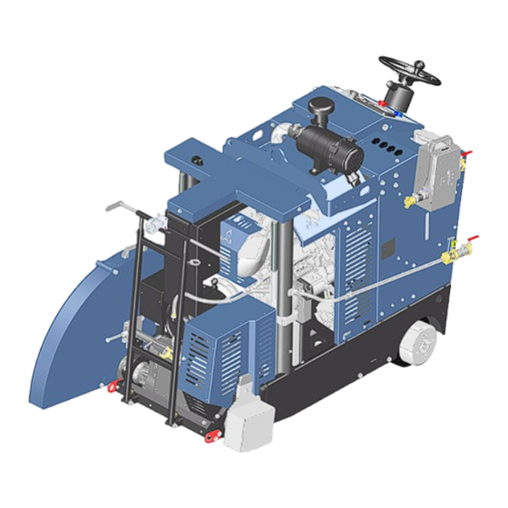
Page 18: Device Description
DEVICE DESCRIPTION 1.9. Designation of the machine parts Pos. 1 Steering wheel Pos. 8 Belt cover Pos. 2 Control panel with emergency stop button Pos. 9 Steering rod Pos. 3 Air filter Pos. 10 Blade guard Pos. 4 Lifting point for crane transport Pos. - Page 19 Pos. 14 Gear selector lever, synchronized/neutral/counter Pos. 19 Rear lashing point rotation Pos. 14a 4-speed manual gearbox (only with SG option) Pos. 20 Water separator Pos. 15 Upper lashing point Pos. 21 Engine oil and oil filter dipstick Pos. 16 Engine coolant filler neck Pos.
- Page 20 Pos. 24 12V sockets Pos. 27 Battery Pos. 25 Blade guard control panel (optional) Pos. 28 Parallel shaft gearmotor Pos. 26 Alternative steering wheel position Pos. 29 Access cover for chain tensioner and steering 20/108...
-
Page 21: Technical Data
1.10. Technical data MULTICUT 590 G MULTICUT 590 SG Max. cutting depth 520 mm 600 - 1200 mm Max. saw blade Ø (fresh concrete 400 - 450 mm) 25.4 mm (castle nut M24) Saw blade arbor 35 mm (6 x M12 -TK 120 mm) Ø... -
Page 22: Sound Power Level
Take regular breaks when working with the machine. The specified value was determined with the maximum saw blade diameter of 1000 mm. The effects can be inversely proportional to the weight of the operator. Vibration total value: Multicut 590 G / SG below 2.5 m/s 22/108... -
Page 23: Exhaust Gases
1.13. Exhaust gases DANGER Toxic exhaust gases The exhaust gases of the combustion motor contain carbon monoxide. It is an invisible, odorless and tasteless gas that can cause unconsciousness and suffocation. It can accumulate quickly in closed rooms and remain there for hours, even after the motor was switched off. Never operate machines with combustion engines in closed or confined spaces ... -
Page 24: Commissioning
2. COMMISSIONING 2.1. Tools (saw blade) NOTICE Selection of the tool No rotating tool, whose maximum speed is lower than the rated speed of the machine, must be used. Defective or broken tools must be replaced immediately. Tool storage The tools used must be protected from moisture. The diamond segments must be protected from damage. Saw blade rotational For optimum cutting performance, the speed of the saw blade must be adapted to the material to be cut. -
Page 25: Water Pump
2.2. Water pump Option The removable water pump is attached to the side of the machine and supplies the saw blade with water. The water connection is made via GEKA couplings. Power supply via 12V plug. The pump has a strainer insert with a transparent cover for daily visual inspection and cleaning. -
Page 26: Refueling With Fuel
2.3. Refueling with fuel WARNING Danger of fire Danger of burns or serious injury due to fire or explosion of fuel vapors. Smoking is absolutely prohibited during the process Remove all flammable sources Do not overfill the tank or spill fuel ... -
Page 27: Saw Blade Installation/Change (Tool)
2.4. Saw blade installation/change (tool) WARNING Danger of cutting and crushing injuries from rotating parts Rotating saw blade or flange can catch and sever clothes or body parts. Switch off the engine and remove the ignition key Before working on the machine, all parts must be stationary. ... - Page 28 Sequence: Loosen the screw (Pos. 1) on the rear of the blade guard (Pos. 2) Remove the blade guard upwards using the handle Remove the flange screws (Pos. 3) with the on-board tool and remove the pressure disk NOTICE Saw blade installation When installing the saw blade, make sure that the flange surfaces are clean.
- Page 29 NOTICE Pressure disc for large saw blades From a saw blade diameter of 800/1000 mm, a larger pressure disc and an additional ring (180 mm) must be fitted to increase the clamping surface. Pressure disc kit Ø35mm for blade sizes ≥...
-
Page 30: Check Drive Belt Tension
Check drive belt tension WARNING Danger of retraction and crushing Body parts and clothing can be retracted on contact with the belt drive. Danger of cutting and crushing injuries up to the severity of amputations. Removing or opening the belt cover or engaging in the rotating belt drive is prohibited This work may only be carried out when the pulley is stationary and the drive motor is switched ... -
Page 31: Replace / Retension V-Belt
2.5. Replace / retension V-belt WARNING Danger of cutting and crushing Body parts and clothing can be retracted on contact with the belt drive. Danger of cutting and crushing injuries up to the severity of amputations. Removing or opening the belt cover or engaging in the rotating belt drive is prohibited ... - Page 32 When cutting in the counter rotation, it is advisable to move the tensioning pulley to the rear. Converting the tension pulley for counter rotation Synchronization Counter-rotation 32/108...
- Page 33 NOTICE Replacing belts We strongly recommend that you only ever replace complete LISSMAC belt sets. Belt sets from other manufacturers may not be able to transmit the required power. The simultaneous use of old and new belts halves the service life of new belts!
-
Page 34: Changing The Cutting Shafts (Only For Version G)
Changing the cutting shafts (only for version G) Conversion kit To change the speed of the MC590 G, the cutting shaft must be replaced with the corresponding belt pulleys and matching V-belt set. Remove the ignition key. Remove the blade guard. Loosen the cutting shaft bracket on both sides and slacken the belt. - Page 35 Remove the V-belt and lift the saw shafts out of the bearing shell. Clean and grease all bearing surfaces. Insert the cutting shaft for the desired speed. CAUTION! Take care not to damage the speed sensor when inserting the shaft! Replace V-belt sets and belt pulleys as required.
-
Page 36: Assignment Diagrams (Only For Version G)
Assignment diagrams (only for version G) #1092814 SPZ 93 x 7 14 x =101010 rpm XPZ 1112 Super XE SPZ 134 x 7 #1092816 10 x SPZ 125 x 5 = 1380 rpm XPZ 1162 Super XE SPZ 132 x 5 #1092818 SPZ 180 x 4 = 2475 rpm... -
Page 37: Transport
3. TRANSPORT 3.1. Transport position WARNING Crushing due to unsecured machine Injuries due to the unintentional change of the position of the machine or the falling of parts. Only transport the floor saw in transport position. Secure the floor saws using attachment points NOTICE Machine transport Avoid large inclinations when transporting the floor saw. -
Page 38: Relocating Using A Crane
3.2. Relocating using a crane WARNING Suspended loads Danger of injury due to falling parts. Do not stay under hoisted machines or parts. Only use undamaged hoisting devices with the sufficient load bearing capacity and length. The machine must only be moved in the transport position. ... -
Page 39: Securing The Machine For Transport
3.3. Securing the machine for transport WARNING Injuries through slipping or tilting of the machine Parts of the body can be crushed if the machine is accidentally moved out of position. Only ever transport the machine in transport position. Secure the machine at the suitable attachment points. -
Page 40: Control Panel On The Floor Saw
CONTROL PANEL ON THE FLOOR SAW NOTICE Operating the machine Before starting the floor saw, you must first familiarize yourself with its operation. Personnel working on the machine must have read the operating manual, in particular the chapter on safety notices, before starting work. Pos. -
Page 41: Hmi Control Unit
3.4. HMI control unit Home page The operator can call up various menus to display and change machine values and settings. Rotary push button Pos. 1 Input fields and functions are selected by turning and activated by pressing. Pos. 2 To the settings preselection page Pos. - Page 42 3.4.1. Dashboard The dashboard provides the user with the most important information at a glance. Pos. 1 Zero position of the depth measurement Pos. 8 Error messages Pos. 2 Lowering speed in % Pos. 9 Indicator of current cutting depth in mm Pos.
- Page 43 3.4.2. Preselection page settings Indicators and settings for cutting mode. Cutting mode settings Preselection is made using the rotary push button. (The current selection field is marked with a red border). The highlighted selection field is activated by pressing it. Activated functions are shown with a green border.
- Page 44 3.4.3. Fault memory In this menu, the detected faults are displayed as Diagnostic Trouble Code (DTC). Engine control errors are displayed as a SPN-FMI number pair (Suspect Parameter Number - Failure Mode Identifier) in accordance with SAE J1939 standardization. Contact the service department with this code if an error cannot be deleted. Pos.
- Page 45 3.4.4. Automatic feed The automatic feed is activated via the soft button. The activated control is indicated by a green frame. When inactive, the frame is black. Pos. 1 Rotary push button Indicators Pos. 2 Direct selection button automatic feed Pos.
- Page 46 3.4.5. Display settings In the display settings menu, the operator can adjust the brightness of the display backlight and the buttons. Pos. 1 Rotary push button Indicators Pos. 2 Direct selection button display settings Pos. 3 Display brightness Pos. 4 Brightness keypad Setting the brightness Press the „Display settings“...
- Page 47 3.4.6. Service menu This service menu is primarily for service technicians. The operator does not need this menu in daily use. Only level 1 (indicator of function monitoring and changeover of units) does not require a password. Pos. 1 Rotary push button Indicators Pos.
- Page 48 3.4.7. Service level 1 Changeover of the displayed units and overview of the control statuses. This service menu is primarily for service technicians. The operator does not need this menu in daily use. Access code: 4444444 Pos. 1 Rotary push button Pos.
- Page 49 3.4.8. Overview of motor parameters Summary of important system information The „Motor parameters“ menu can be accessed at any time via the overview button (Pos. 2). Pos. 3 Motor speed Pos. 9 Zeroing average consumption Indicators Pos. 4 Cooling water temperature Pos.
- Page 50 3.5. Warning indicators NOTICE Absolutely observe error messages Warning lamps indicate an error case in the system. In order to avoid damages to the machine, the displayed error must be rectified immediately. General warning Determine cause via error code and rectify promptly.
-
Page 51: Operation
4. OPERATION 4.1. Safety • The floor saw may only be operated by one person. General rules Ensure that other people vacate the work area or set up a barrier. • The operator must not leave the machine with the engine running. •... - Page 52 WARNING Danger of being cut Serious injuries due to a rotating saw blade or ejected parts. Only cut with the blade guard closed. Keep a safe distance. Never touch the rotating saw blade. Wear personal protective equipment. ...
-
Page 53: Start-Up Preparations
4.2. Start-up preparations Initial preparation In order to use the floor saw safely and properly, the following conditions must be met: • Check the dry extraction for damages, loose screw connections and for the completeness of the attachments parts • Check the engine oil level •... -
Page 54: Setting The Lowering Speed
Setting the lowering speed The lowering speed of the blade is set using the soft button. The speed should only ever be adjusted gradually and should not be set too high in order to prevent damage to the tool and machine. Press the preselection button (1) Use the rotary push control (2) to set the lowering speed to the appropriate value and save the value by pressing it. -
Page 55: Gear Preselection
Gear preselection Cutting is only possible in cutting gear. Press the soft button (1) to change gear. Cutting gear Rapid traverse / relocation Switchable sockets Sockets 1 and 2 on the control panel can be switched via the control unit. If required, press the corresponding soft button (2) to switch the power supply to the respective socket on or off. -
Page 56: Turbo Mode
Turbo mode Turbo mode enables the machine to be moved faster for relocating on the cutting line. When the button is pressed, the travel speed increases to its maximum. This function is only available in cutting gear. If required, press and hold the corresponding soft button (2) to activate turbo mode. Error message A pending error is displayed in this field. -
Page 57: Speed Preselection On The Manual Gearbox
Speed preselection on the manual gearbox NOTICE Gear change only when stationary The four gears allow the optimum tool speed to be set according to the saw blade size and the material being cut. Incorrect operation will result in serious damage to the gearbox. ... -
Page 58: Switching From Counter Rotation To Synchronized Cutting
Switching from counter rotation to synchronized cutting NOTICE Switching the direction of rotation only when stationary Depending on requirements, the changeover can be used to counter rotation or synchronized cutting. Serious gearbox damage due to incorrect operation Only switch when the diesel engine is switched off ... -
Page 59: Starting And Stopping The Engine
4.3. Starting and stopping the engine Starting Turn the ignition key to ignition position 2. Wait until the multifunction display is fully raised. Depending on the outside temperature, the preheating symbol appears in the indicator when the engine is cold. Leave the ignition key in position 2 for 3 to 10 seconds and preheat. -
Page 60: Stopping In An Emergency
Stopping Turn the ignition key to 0. Remove the ignition key. The machine DO NOT switch off via emergency stop! Stopping in an emergency Emergency stop In the event of an emergency or loss of control, press the emergency stop button without hesitation. -
Page 61: Zeroing The Cutting Depth Measurement
Zeroing the cutting depth measurement The cutting depth must always be zeroed before starting to cut so that the correct cutting depth can be shown on the display. Place the saw blade over the cutting line and lower it until it scratches the surface. Pressing the preselection button (1) sets the zero point for the subsequent measurement of the cutting depth. -
Page 62: Preselecting The Cutting Depth
Preselecting the cutting depth The cutting depth can be preset before cutting begins. Maneuver the floor saw into position and lower the blade until it scrapes the surface. Set the depth measurement to zero by pressing the preselection button (Pos. 1). Press the rotary push control (2) The setting page opens. -
Page 63: Cutting With The Floor Saw
4.2. Cutting with the floor saw WARNING Ejected parts If the saw blade for wet cutting is not supplied with sufficient cooling water, segments can break out and there is a risk of overheating. The grinding dust is not sufficiently bound. ... - Page 64 • Emergency stop unlocked Prerequisites • Fuel in the tank • Water supply connected • Blade speed and direction of rotation are set correctly on the gearbox • Feed speed potentiometer is set to 0 Cutting 1. Start the diesel engine (Pos. 7) and maneuver the floor saw with the blade over the cutting line. 2.
-
Page 65: Cutting With The Blade Guard Opened
4.3. Cutting with the blade guard opened WARNING Cutting with the blade guard opened Serious injuries due to rotating saw blade or ejected material. Keep the machine’s cutting area free Never touch the rotating saw blade Wear a safety helmet, work shoes and safety goggles ... -
Page 66: Repositioning The Floor Saw
4.4. Repositioning the floor saw WARNING Danger of injury due to rotating saw blade By touching the rotating saw blade clothes can be pulled in and limbs severed. Any movement of the machine outside the area where cutting work is to be performed must be ... -
Page 67: Switching Off The Floor Saw
Relocating the floor Raise the blade approx. 10 cm from the ground (Pos. 5). Close the water supply. Set the feed potentiometer to zero (Pos. 6) or move the joystick (Pos. 4) to the neutral center position. ... -
Page 68: Change From Right To Left Cutting
Change from right to left cutting WARNING Cutting injury and danger of being drawn in by the rotating saw blade Touching the rotating saw blade can result in cuts, severed limbs and burns. It is forbidden to remove or open the saw blade guard, or to reach into the rotating saw blade ... - Page 69 4.6. Fuses MC 590 Always replace fuses with ones of the same type only. Rated -4AA2 Fuses Function Relay (12V-30/20A) current: Socket 1 Socket 1 Socket 2 Starter Socket 2 Outputs Ignition Brake lift Starter Brake feed Display Outputs Brake lift Brake feed Rated -5AA1...
- Page 70 4.7. Battery and charger Battery Clean battery ODYSSEY PC2150 12V 92Ah - 2100A starting current (replacement only with the same type) If the battery voltage drops below 11V at any time, the control unit deactivates. Check battery voltage regularly. Charge weak batteries or replace old battery. WARNING Danger of electric shock, chemical burns and explosion Explosive oxyhydrogen gas can be produced when charging the battery.
- Page 71 Charging voltage between 14.4-14.7V (not below 13.2V) CAUTION! Read and follow the safety notice in the charger manufacturer's original operating manual. Lissmac cannot be held liable for injuries, damage to the battery and/or the machine caused by the use of unsuitable charging solutions. Charger...
- Page 72 Remedy: Check characteristic curve setting; repeat charging process. flashing Cause: Overtemperature Device switches off Remedy: Allow the device to cool down, the charging process will continue automatically. The technical data can be found on the characteristic curve data sheet enclosed with the LISSMAC charger. 72/108...
-
Page 73: Drain Cooling Water If There Is A Danger Of Frost
Drain cooling water if there is a danger of frost NOTICE Drain the water if there is a danger of frost To prevent frost damage to the gearbox, the cooling water must be drained completely before the machine cools down. Sequence: 1. -
Page 74: Fitting The Running Board (Accessory #1206256)
Fitting the running board (accessory #1206256) Attachment Screw the bracket to the frame on the right or left as required. Screw the bracket to the bottom of the frame. Determine the desired position. The running board can be mounted in the middle or offset by 95 mm to the left or right. Connect the running board and bracket with bolts and secure with cotter pins. - Page 75 Folding in Pull the spring bolt at the bottom right of the connecting joint and fold in the running board. Secure the running board for transportation with a linch pin. 75/108...
-
Page 76: Hydraulic Option For Additional Units
Hydraulic option for additional units Attachment The hydraulic option is installed ready for connection at the factory. Extraction The additional units are connected via quick couplings. system connection Activation The hydraulic unit is activated (on - vertical lever) or deactivated (off - horizontal lever) using the lever on the side Make sure to deactivate the hydraulic unit if no additional units are connected. -
Page 77: Connecting And Disconnecting Hydraulic Plug-In Couplings
Connecting and disconnecting hydraulic plug-in couplings WARNING Injection of oil from high-pressure hydraulic lines A small leak in the high-pressure lines can inject oil under the skin and cause gangrene and amputations. Always keep protective hoses in good condition Do not drop quick couplings and do not expose them to shocks or impacts ... -
Page 78: Attach Holder For Front Units
Attach holder for front units Remove the belt cover and underbody. Dismantle and store the sheet- metal angles. Screw bracket to frame. Screw the retaining rail to the brackets. Notice: When used without the front unit, the rail must be removed in order to be able to fold up the dipstick. -
Page 79: Maintenance
5. MAINTENANCE 5.1. Maintenance WARNING Danger of injury due to rotating parts. Serious injuries due to rotating saw blade or belt drive Maintenance and repairs must only ever be carried out when the machine is switched off. Maintenance and repairs may only be carried out by qualified personnel. ... -
Page 80: Operating Materials
5.2. Operating materials Diesel Only fill up with sulphur-free diesel fuel in accordance with EN 590 / ASTM D 975 (ULSD). If other fuels or fuel mixtures are used, the emission values will change and the warranty will become void. Motor oil Only use engine oil SAE 10W-40 with specification ACEA E6/E7/E9 (API CK-4). - Page 81 5.3. Replacing air filter cartridges The air filter filters the ambient air and prevents the penetration of foreign matter into the combustion chamber. Dust builds up in the air filter over time and reduces the air flow. The performance is reduced and the motor can be damaged thereby. We therefore recommend checking the air filter regularly and replacing it if necessary.
-
Page 82: Gearbox Compartment
Gearbox compartment Pos. 1 Battery Pos. 2 Gear motor travel drive Pos. 3 Maintenance hatch steering linkage / chain tension Pos. 4 Release motor brake Pos. 5 Diesel tank NOTICE Feed speed in cold weather The electric drive does not immediately reach the usual top speed at low temperatures. The reason for this is that the gear oil becomes viscous in cold weather. -
Page 83: Retensioning The Drive Chain
5.4. Changing the coolant We recommend the use of 50% glycol and 50% distilled water. PERKINS ELC long-term coolant Replacement every 6000 operating hours / 3 years Antifreeze according to ASTM D6210 Replacement every 3000 operating hours / 2 years Antifreeze according to ASTM D4985 Replacement every 3000 operating hours / 1 year The cooling system contains 15 liters of fluid. -
Page 84: Drive Chain Wear Test
5.5. Drive chain wear test NOTICE Check drive chain wear regularly The drive chain is an essential component for securing the position of the machine. If the chain fails, the machine can no longer be braked. Lubricate the chain regularly ... -
Page 85: Cleaning The Water Pump Set
NOTICE Always replace the drive set together If the chain wheel and sprocket have run in, the entire drive set including the chain must be replaced. It does not make sense to replace individual elements. Old components wear out the new components much faster. Cleaning the water pump set Check the strainer insert daily before starting work. -
Page 86: Drain The Engine Oil
Drain the engine oil NOTICE Dispose of engine oil safely Avoid environmental pollution and observe country-specific regulations. When draining the engine oil, a collecting vessel must be placed underneath Dispose of used engine oil properly and in an environmentally friendly manner. ... - Page 87 87/108...
-
Page 88: Lubricating The Lift
Lubricating the lift Check the oil level daily before starting work. To read the correct level, the floor saw must be raised so that the motor axle is horizontal. Threaded rods Unscrew the cover on the lifting linkage. Raise the machine until the grease nipple is visible in the opening. -
Page 89: Lubrication Points
Lubrication points The combustion engine must be switched off before carrying out maintenance or repair work. Secure the machine against being accidentally switched on again. Maintenance and service work must only be carried out by qualified technical personnel. Secure the machine with a crane when working underneath it. Daily! Daily! 89/108... -
Page 90: Rectification
Rectification The combustion engine must be switched off before carrying out maintenance or repair work. Secure the machine against being accidentally switched on again. Maintenance and service work must only be carried out by qualified technical personnel. NOTICE In the event of cutting problems, check the following points: ... -
Page 91: Maintenance Schedule
Maintenance schedule This section is to serve as evidence for the maintenance and service book already supplied. All maintenance and service work must be registered as evidence. Machine/type: Serial number/year of manufacture: Date Maintenance or service work carried out Date/signature 91/108... -
Page 92: Warranty
WARRANTY The warranty for this machine is 12 months. Warranty is only provided for the wear parts listed below if the wear is not due to operation. Wear parts are parts which undergo operation-dependent wear during the intended use of the machine. These parts have varying service lives, depending on the intensity with which they are used. - Page 93 Original EC Declaration of Conformity This EC declaration of conformity applies to the following machine: LISSMAC Floor saws MULTICUT 590 in version G and SG. This declaration only refers to the machine in the condition in which it was sold; parts retrofitted by the end user and / or retrospective intervention is not covered by this declaration.
-
Page 94: Circuit Diagram
6. CIRCUIT DIAGRAM 94/108... - Page 95 95/108...
- Page 96 96/108...
- Page 97 97/108...
- Page 98 98/108...
- Page 99 99/108...
- Page 100 100/108...
- Page 101 101/108...
- Page 102 102/108...
- Page 103 103/108...
- Page 104 104/108...
- Page 105 105/108...
- Page 106 106/108...
- Page 107 107/108...
- Page 108 108/108...
Need help?
Do you have a question about the MULTICUT 590 G and is the answer not in the manual?
Questions and answers