Table of Contents
Advertisement
Quick Links
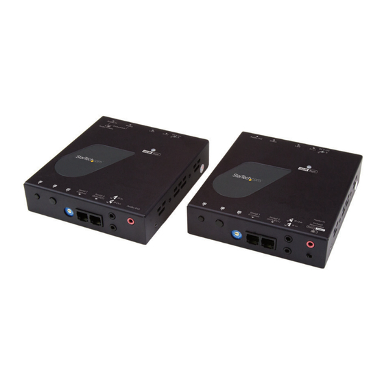
HDMI® Over IP Extender Kit - 4K
ST12MHDLAN4K
FR: Guide de l'utilisateur - fr.startech.com
DE: Bedienungsanleitung - de.startech.com
ES: Guía del usuario - es.startech.com
NL: Gebruiksaanwijzing - nl.startech.com
PT: Guia do usuário - pt.startech.com
IT: Guida per l'uso - it.startech.com
For the latest information, technical specifications, and support for
this product, please visit www.StarTech.com/ST12MHDLAN4K.
Manual Revision: 07/25/2019
*actual product may vary from photos
Advertisement
Table of Contents

Related Manuals for StarTech.com STCST12MHDLAN4K


Summary of Contents for StarTech.com STCST12MHDLAN4K
- Page 1 HDMI® Over IP Extender Kit - 4K ST12MHDLAN4K *actual product may vary from photos FR: Guide de l’utilisateur - fr.startech.com DE: Bedienungsanleitung - de.startech.com ES: Guía del usuario - es.startech.com NL: Gebruiksaanwijzing - nl.startech.com PT: Guia do usuário - pt.startech.com IT: Guida per l’uso - it.startech.com...
- Page 2 StarTech.com. Where they occur these references are for illustrative purposes only and do not represent an endorsement of a product or service by StarTech.com, or an endorsement of the product(s) to which this manual applies by the third-party company in question. Regardless of any direct acknowledgement elsewhere in the body of this document, StarTech.com hereby...
-
Page 3: Table Of Contents
Table of Contents Introduction ....................1 Packaging contents ..........................1 System requirements ..........................1 Product diagram ..................2 Transmitter Unit ............................2 Receiver Unit ............................... 3 Installation ....................4 Preparing your site............................ 4 Hardware installation ..........................4 Software installation ..........................6 Technical support ...................7 Warranty information ................7 Instruction manual... -
Page 4: Introduction
Introduction Packaging contents • 1 x HDMI over IP transmitter • 1 x HDMI over IP receiver • 2 x universal power adapters (NA, EU, UK, ANZ) • 2 x mounting brackets • 2 x CAT5e cables • 2 x RJ11 to RS232 adapters •... -
Page 5: Product Diagram
Product diagram Transmitter unit Front view Back view Function 1 button Network status LED Function 2 button 10. Reset button Dip rotary switch 11. LAN port (RJ-45) Serial control port (not active)* 12. HDMI input port (audio/video) Serial extension (RS-232 signal) 13. -
Page 6: Receiver Unit
Receiver unit Additional receiver units sold separately: StarTech.com SKU: ST12MHDLAN4R Front view Back view Function 1 button Function 2 button Dip rotary switch Serial control (not active)* Serial extension (for extending RS-232 signal) Infrared (in) and (out) ports Audio in port**... -
Page 7: Installation
Installation Preparing your site Note: The HDMI extender kit lets you extend your 4K30 video signals over a Gigabit LAN network, beyond the typical cable length restriction of 330 ft. (100m) of Gigabit network portals. Refer to the manufacturer of the network equipment to determine the length restriction and to ensure the transmitter unit and receiver unit(s) are all within the restricted range of the nearest network portal. - Page 8 Verify that the image from your video source appears on video display(s) attached to the receiver unit(s). HDMI over IP receivers HDMI displays Gigabit network switch HDMI over IP transmitter HDMI video source (Additional receiver units sold separately, StarTech.com SKU: ST12MHDLAN4R) Instruction Manual...
-
Page 9: Software Installation
Android™ for your smartphone or tablet, and for the Google Chrome™ browser. To install the software: Visit http://www.StarTech.com/ST12MHDLAN4K, using the device you intend to install software on. Under the overview tab, select the link for the store that corresponds with your device. - Page 10 Software operation Connecting your transmitters and receivers to the software Note: To ensure the application functions properly, your router must support IGMP snooping. Please refer to your network switch or router documentation to ensure IGMP snooping is supported and enabled. Ensure your computer, smartphone or tablet that the software has been installed on is connected to the same network as your transmitter(s) and receiver(s), and launch the application.
- Page 11 Once launched, the application will open on the Devices tab, and will automatically search for transmitters and receivers on your network and list them within the Devices tab. Note: you can re-initiate the device search, by selecting the refresh button in the top right-hand corner of the Devices tab.
- Page 12 By default, each video device will have an IP address in the range of 169.254.x.x with a subnet mask of 255.255.0.0. Each transmitter and receiver must have an IP address in the same range, and have an identical subnet mask as each other, and the tablet, smartphone or computer you have the software installed on.
- Page 13 b. Click the edit Icon listed in the IP address section. c. Select Static IP and type an IP address and mask for the device. Select DHCP and your network automatically assign an IP address and mask to for the device in the range of the rest of your network devices. Instruction Manual...
- Page 14 Note: DHCP must be enabled on your network to automatically assign an IP address and mask in that range. Switching your remote displays between video sources Once the application is launched, select the Switches tab. A list of each connected receiver will be displayed with all available transmitters displayed beside them.
- Page 15 Note: if the receiver is part of a video wall it will be indicated with a button that lists the wall configuration and the location of the receiver. Instruction Manual...
- Page 16 To assign a video source, or change your video source, select the transmitter listed next to your receiver that you’d like to display. The transmitter will turn yellow and your video source will switch on the remote display. Note: If a receiver that was part of a video wall configuration is altered, that display will no longer be part of the video wall configuration.
- Page 17 Note: a Wall Name will be listed by default, once you type a new name the default name will be overwritten. The next page in the wizard will create an example of the video wall with the number of rows and columns you specified. You will need to use this example to specify which receivers are represented within your video wall configuration.
- Page 18 Note: If you would like to see the receiver device name on each screen, so you can easily identify which display is connected to each receiver, please select the show device names on screen switch. This can be deactivated once you have identified your displays.
- Page 19 On the bezel compensation window, enter the following measurements in millimeters (mm): screen width of each display (ScreenX), screen height of each display (ScreenY), total width of each display (DisplayX) and total height of each display (DisplayY). Then click the Save button. The wizard is now complete and your created video wall configuration will appear on the Walls tab.
- Page 20 Notes: • The display indicators will show the status of the current wall. Blue indicates that the display is active, Grey indicates it is being used for another wall or switch. • You can adjust the settings defined for each video wall configuration or delete your video wall configuration by clicking the arrow next to each video wall.
- Page 21 Help: Lists information and walk-throughs regarding operation of the application. Device Search Mode: Enables you to define your preferred method of transmitter and receiver identification over your network that the software uses. You can choose between two methods of identification: Multicast DNS or Target IP for your transmitters and receivers. Multicast DNS: is the default setting and will search automatically for devices over the network.
-
Page 22: Technical Support
Limitation of liability In no event shall the liability of StarTech.com Ltd. and StarTech.com USA LLP (or their officers, directors, employees or agents) for any damages (whether direct or indirect, special, punitive, incidental, consequential, or otherwise), loss of profits, loss of business, or any pecuniary loss, arising out of or related to the use of the product exceed the actual price paid for the product. - Page 23 StarTech.com is an ISO 9001 Registered manufacturer of connectivity and technology parts. StarTech.com was founded in 1985 and has operations in the United States, Canada, the United Kingdom and Taiwan servicing a worldwide market.
Need help?
Do you have a question about the STCST12MHDLAN4K and is the answer not in the manual?
Questions and answers