Stenner Pumps Classic Series Basic Service Manual
Hide thumbs
Also See for Classic Series:
- Installation and maintenance manual (100 pages) ,
- Basic service manual (48 pages) ,
- Quick start manual (2 pages)
Table of Contents
Advertisement
Quick Links
Advertisement
Table of Contents

Related Manuals for Stenner Pumps Classic Series


Summary of Contents for Stenner Pumps Classic Series
- Page 1 BASIC SERVICE MANUAL Classic Series Pumps...
- Page 3 Always follow safety & operational instructions in the Classic Series manual. The pump is designed for installation and service by properly trained personnel. Meet Max the Tube… the one who does all the work.
-
Page 4: Table Of Contents
Table of Contents GENERAL INFORMATION Safety Information Supplies Classic Series Single Head Adjustable Pump 7 INSTALLATION POINTS Installation Diagram Installation Suction and Discharge Lines Connections SUBASSEMBLY CONNECTIONS Rivet and Slot Identification Separate Subassemblies Reconnect Subassemblies PUMP TUBE Pump Tube Basics... -
Page 5: Safety Information
Safety Information USA and Canada 800.683.2378, International 904.641.1666. -
Page 6: Supplies
Supplies #2 Phillips head screwdriver Flat head screwdriver 3/8" open end wrench (to change index pin lifter) Aquashield Non-citrus cleaner Needle-nose pliers Utility knife www.stenner.com... -
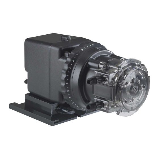
Page 7: Classic Series Single Head Adjustable Pump
Classic Series Single Head Adjustable Pump THREE SUBASSEMBLIES Motor Feed Rate Control (FRC) Pump Head Subassemblies make replacement in the field quick & convenient. USA and Canada 800.683.2378, International 904.641.1666. -
Page 8: Installation Diagram
Installation Diagram for Single Head Pump Always use Rain Roof for outdoor use or if pump is subject to washdowns. Rain Roof slides into wall mounting bracket (no tools necessary). Vertical Wall Mounting Bracket (requires 2 screws) Grounded Power Outlet; protected by Ground-Fault Circuit-Interrupter (GFCI) Disassembled View... -
Page 9: Installation
Installation Mount the single head pump vertically and use the spill recovery to drain chemical back to the tank in the event of tube failure. Vertical installation will help prevent chemical from collecting in the tube housing and on the floor. -
Page 10: Suction And Discharge Lines
Suction and Discharge Lines Allow slack in both the suction & discharge lines to prevent stress on the tube and fittings. The slack allows the tube fittings to flex to help reduce the chance of breakage and leaks. The suction line should not be flush with the nose of the strainer. -
Page 11: Connections
Connections The connections to the pump tube fittings and to the injector are a compression type seal. Overtightening the connections breaks the seal and can cause a twisted tube, damaged fittings, or crushed ferrules. A twisted tube will not stay centered & decreases tube life. -
Page 12: Rivet And Slot Identification
Rivet and Slot Identification Indentation Rivet (3) Motor shaft and pressure spring coated with Aquashield The pressure spring is not needed with the Classic Series Fixed Output Pump. Bump Mounting Plate Rivet Slot (3) Plate Screw (3) www.stenner.com... -
Page 13: Separate Subassemblies
Separate Subassemblies Turn pump off and unplug power cord. Hold feed rate control & turn pump head clockwise until it stops. Pull pump head straight out. Hold motor, grasp feed rate control & turn clockwise until it stops. Pull feed rate control straight out. Feed Rate Control Pump Head Motor... -
Page 14: Reconnect Subassemblies
Reconnect Subassemblies RECONNECT FEED RATE CONTROL TO MOTOR On adjustable models, confirm pressure spring is in place, then slide feed rate control onto the shaft. Turn the feed rate control counterclockwise to line up the flat side of the motor shaft (d shaft) with the flat side of the spider in the feed rate control and push towards the motor. -
Page 15: Pump Tube Basics
Pump Tube Basics The tube is the workhorse of the pump and is perishable. It will eventually reach the end of its service life, indicated by: The very first tube replacement indicates the expected service life for the tube & the specific application if other conditions are not the cause. Before tube replacement, confirm if the tube reached its expected life or correct what has caused reduced service life. -
Page 16: Maximize Tube Life
Maximize Tube Life DO NOT use pliers to secure connections or ferrules can be damaged. The 1/4" connecting nut must be finger tightened only. DO NOT pull on the tube fittings to stretch the tube. Follow instructions in the manual to run the roller assembly in the collapsed position 4 minutes to relax tube. -
Page 17: Visual Reference
Visual Reference When the tube is pressed against the tube housing wall, the shape formed can be used as a visual reference. A tear drop pattern is normal and confirms the roller assembly has been expanded after tube replacement. A diamond pattern indicates excessive back pressure. Excessive back pressure is caused by any blockage, or a clogged duckbill or when the system pressure exceeds the tube pressure rating. -
Page 18: Poor Conditions Reduce Tube Life
Poor Conditions Reduce Tube Life SEIZED ROLLERS Chemical exposure allows corrosive chemicals to collect on the roller bushings causing rollers to seize. Seized rollers stretch and pull instead of smoothly rolling over the tube. SOLUTION Confirm chemical compatibility with housing and tube material. Review factory installation instructions. - Page 19 Poor Conditions Reduce Tube Life EXCESSIVE BACK PRESSURE AT THE POINT OF INJECTION DISCHARGE LINE Calcium or mineral deposits in the injection fitting can cause blockage or restriction creating back pressure exceeding the tube pressure rating. SOLUTION Insert #2 Phillips head screwdriver through injection fitting into the pipe to break up accumulated deposits.
- Page 20 Poor Conditions Reduce Tube Life SPLIT ALONG SIDE OF THE TUBE If the tube is not centered and it continuously rides against the edge of the tube housing, it will split. SOLUTION Always follow the tube replacement instructions in the manual which includes centering the tube. NOTE: The tube will not center if it is twisted during installation or if the rollers are worn.
-
Page 21: Tube Replacement
Tube Replacement PREPARATION Follow all safety precautions prior to tube replacement. Prior to service, pump water or a compatible buffer solution through the pump and suction & discharge lines to remove chemical and avoid contact. REMOVE TUBE Turn pump off and unplug power cord. On the adjustable model, ensure feed rate control is set to 10. - Page 22 Tube Replacement REMOVE TUBE continued Securely hold feed rate or motor (on fixed rate pump). Quickly (snap) rotate cover counterclockwise to collapse roller assembly. The tube will no longer be pressed against the tube housing wall. E NOTE: Counterclockwise is viewed from facing the head of the pump.
- Page 23 Tube Replacement INSTALL TUBE IMPORTANT! DO NOT LUBRICATE PUMP TUBE OR ROLLER ASSEMBLY. Ensure power to pump is off and power cord is unplugged. On the adjustable model, ensure the feed rate is set to 10. H Place new tube in the pump head; use your fingers to center it over the rollers.
- Page 24 Tube Replacement INSTALL TUBE continued With cover latched, plug pump in and turn power on. Allow pump to run the roller assembly in collapsed position for approximately 4 minutes to relax tube. K Turn pump off and unplug power cord. Remove tube housing cover and flip to use as a tool in next step.
- Page 25 Tube Replacement INSTALL TUBE continued ADJUSTABLE MODEL ONLY Expand roller assembly for the Adjustable Model use the cover and gently rotate the roller assembly clockwise to expand roller assembly. The tube will be pressed against the tube housing wall. N & O NOTE: Clockwise is viewed from facing the head of the pump.
- Page 26 Tube Replacement INSTALL TUBE continued FIXED OUTPUT MODEL ONLY Expand roller assembly for the Fixed Model. Slide one latch out to remove from tube housing. Insert latch end into key slot in the vent in rear of motor housing. While pressing latch into rear of motor, gently rotate cover clockwise until it stops.
- Page 27 Tube Replacement INSTALL TUBE continued Apply a small amount of Aquashield to cover bushing ONLY. DO NOT lubricate the pump tube. P 10. Place tube housing cover (feet first) on the tube housing, affix front latches to the cover lip and then press latches back to secure.
- Page 28 Tube Replacement CENTER TUBE Ensure pump is off. Lift latch located between tube fittings, leaving end of latch engaged with the lip on tube housing cover. Leave latch on opposite side closed. R Plug pump in and turn on. Turn tube fitting on suction side not more than 1/8 of a turn in the direction tube must move.
-
Page 29: Pump Head Replacement
Pump Head Replacement REMOVE PUMP HEAD & INSTALL NEW PUMP HEAD ADJUSTABLE MODEL ONLY Turn off Adjustable Model and unplug power cord. To remove pump head, hold feed rate securely, grasp the head and turn clockwise until it stops. A Remove head by pulling it straight out from the pump. - Page 30 Pump Head Replacement REMOVE PUMP HEAD & The illustration show the Classic Adjustable model. INSTALL NEW PUMP HEAD FIXED OUTPUT MODEL ONLY Turn off the Fixed Model and unplug power cord. To remove head, hold motor securely, grasp head and turn clockwise until it stops.
-
Page 31: Feed Rate Control
Feed Rate Control Basics The Feed Rate Control (FRC) adjusts the Dial Ring Setting pump output by utilizing a cam & spring loaded lifter assembly to control the rotation of the roller assembly according to the setting on the dial ring. The dial ring setting controls the amount of cam in the channel. -
Page 32: Feed Rate Control Wear
Feed Rate Control Wear Worn parts affect dosing accuracy. Check the Worn groove in parts for wear if the feed rate control makes plastic cam a skipping or ratcheting sound and/or the flow rate output is less than the setting. At the lower settings, the lifter rides on a large section of the cam and will wear a groove in the cam. - Page 33 Feed Rate Control Wear SEIZED INDEX PIN AND/OR LIFTER ASSEMBLY Water or chemical intrusion will corrode the pin and lifter causing them to seize; the feed rate will malfunction. SOLUTION Replace the index pin and/or lifter assembly as needed. Review factory installation instructions. Check the pump head: –...
-
Page 34: Feed Rate Control Parts Replacement
Feed Rate Control Parts Replacement Remove and set aside: 3 screws, mounting plate, spider, dial ring & index plate If needed, replace lifter & re-assemble. remove assembly from spider. A holder. B pin. C locker* onto holder threads. D careful not to cross thread. Invert worn index plate for use or install new one. - Page 35 Feed Rate Control Parts Replacement Apply Aquashield to inside of dial ring or it will be difficult to rotate. F Insert cam elbow into dial ring boss. G 10. While keeping elbow in boss & cam in channel, pivot dial ring to gently place onto housing.
-
Page 36: Motor Basics
Motor Basics The motor has a cylindrical rotor with shaft encased within a magnetic coil. When power is applied to the coil, the rotor rotates counterclockwise. The helical end of the rotor engages the series of gears in the gear case. Rotor Assembly Coil Helical End... -
Page 37: Motor Malfunction Causes
Motor Malfunction Causes LIQUID INTRUSION The motor is fan cooled and needs proper ventilation while protecting it from water intrusion. SOLUTION Mount the single head pump vertically with pump head downward and use the rain roof in outdoor installations, in areas subject to wash downs, or in wet environments. -
Page 38: Rotor Assembly Replacement
Rotor Assembly Replacement Rotor assembly includes B, D & F. From this view, the copper Remove and set aside: rods are at the top right. Copper Rods B (discard old fan) Remove and discard the rotor F and 2 bearing brackets D. -
Page 39: Coil Replacement
Coil Replacement Disconnect power to pump. Remove motor base & 2 motor screws. Invert pump and use the pump head & feed rate control as a stand to work on the motor. Refer to illustration. Remove fan and set aside. Motor Motor Screws Feed Rate Control... - Page 40 Coil Replacement Disconnect ground wire with eyelet and set screw aside. Cut coil wires from the motor cover at wire nuts. Cut power cord wires from the cover at wire nuts. Set aside cover. Remove and set aside: Remove coil and discard. Ground Wire with eyelet Bearing Bracket Set Screw...
- Page 41 Coil Replacement Install new coil. Place bracket on rotor and securely seat onto coil. Use the image below as a reference to confirm the coil is installed in the correct orientation. On this view, the copper rods are located at the top right.
- Page 42 Coil Replacement 12. With wire strippers set at 16 gauge, strip approx. 1/2” from the power cord & on/off switch wires. 13. Screw ground wire to the coil. 14. Crimp the stripped wires to each of the new coil wires. 15.
-
Page 43: Gears
Gears Motor Metal Reduction Gear Gear Case Phenolic Gear with spacer Motor Shaft & Gear Located in the gear case, the metal reduction gear and phenolic gear control the revolutions per minute (rpm) of the feed rate and pump head. The 45 &... - Page 44 Gears VISUAL DIFFERENCE IN GEAR SETS 45 & 100 Models 26 rpm Both gear diameters 1 3/8" Phenolic Gear Metal Reduction Gear 85 & 170 Models 44 rpm Both gear pinions 9/16" www.stenner.com...
-
Page 45: Gear Wear
Apply a generous amount of Aquashield to gear posts, pinions, gear rings and the motor shaft & gear. Refer to the Trouble Shooting guide in the Classic Series Installation Manual for pump conditions and solutions. USA and Canada 800.683.2378, International 904.641.1666. -
Page 46: Gear Replacement
Gear Replacement Gear Post Phenolic Gear Metal Reduction Gear Thrust Washer Gear Case Phenolic Gear Spacer Motor Shaft & Gear Pressure Spring (adjustable models only) Remove 4 Phillips head screws from gear case cover. Remove gear case cover. Remove gears and inspect thrust washer and posts. To remove posts, grasp with pliers and pull straight out. - Page 47 STENNER PUMPS Series Description Max. Flow Rate Output & PSI Classic Series Electromechanical, fixed output models 170.0 GPD 25 psi or adjustable with 20:1 turndown 40.0 GPD 100 psi S Series Interfaces with process control systems 315.0 GPD 25 psi 9 operational modes, programmable relays 125.0 GPD...
- Page 48 STENNER PRODUCTS Products Description Proportional Injection System Classic 45 or 85 Fixed Rate & Water Meter (3/4", dry contact) & PCM & Flow Indicator ships pre-mounted to a panel for proportional injection based on water system flow. Econ Integrator Econ Integrator or Econ FP &...
- Page 49 NOTES...
- Page 50 NOTES...
- Page 52 STENNER PUMP COMPANY 3174 DeSalvo Road Jacksonville, Florida 32246 USA Phone: 904.641.1666 US Toll Free: 800.683.2378 Fax: 904.642.1012 sales@stenner.com www.stenner.com Hours (EST) Mon.–Fri. 7:00 am–8:00 pm Assembled in the USA with US and international components © Stenner Pump Company All Rights Reserved Product illustrations by David Stiles www.stilesdesigns.com BSME 042524...
Need help?
Do you have a question about the Classic Series and is the answer not in the manual?
Questions and answers