
Subscribe to Our Youtube Channel
Related Manuals for GeoVision GV-GBL12811


Summary of Contents for GeoVision GV-GBL12811
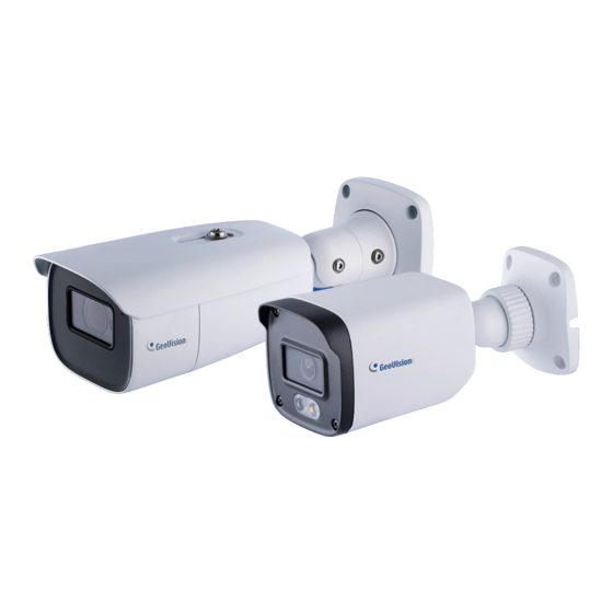
- Page 1 GV-IP Camera User's Manual GV-GBL12811 GV-GBLF2802 Before attempting to connect or operate this product, please read these instructions carefully and save this manual for future use. TVTBL-UM-A...
- Page 2 GeoVision. Every effort has been made to ensure that the information in this manual is accurate. GeoVision, Inc. makes no expressed or implied warranty of any kind and assumes no responsibility for errors or omissions. No liability is assumed for incidental or consequential damages arising from the use of the information or products contained herein.
- Page 3 Preface GV-IP cameras have a variety of models designed to meet different needs. The features described in the manual vary among camera models and versions. Some features may not be available in your camera.
-
Page 4: About The Manual
About the Manual ⚫ This manual is suitable for many models. All examples, screenshots, figures, charts, and illustrations used in the manual are for reference purpose, and actual products may be different with this Manual. ⚫ Please read this user manual carefully to ensure that you can use the device correctly and safely. -
Page 5: Environment
Environment ⚫ Heavy stress, violent vibration or exposure to water is not allowed during transportation, storage and installation. ⚫ Avoid aiming the camera directly towards extremely bright objects, such as, sun, as this may damage the image sensor. ⚫ Keep away from heat sources such as radiators, heat registers, stove, etc. ⚫... - Page 6 Disclaimer Regarding the product with internet access, the use of product shall be wholly at your own ⚫ risks. Our company shall be irresponsible for abnormal operation, privacy leakage or other damages resulting from cyberattack, hacker attack, virus inspection, or other internet security risks;...
-
Page 7: Regulatory Information
Regulatory Information FCC Information FCC compliance The products have been tested and found in compliance with the council FCC rules and regulations part 15 subpart B. These limits are designed to provide reasonable protection against harmful interference. This equipment generates uses and can radiate radio frequency energy and, if not installed and used in accordance with the instruction manual, may cause harmful interference to radio communication. -
Page 8: Table Of Contents
Table of Contents Contents Preface ..........................1 About the Manual ........................ 2 Use of the Product ......................2 Electrical Safety ........................2 Environment ........................3 Operation and Daily Maintenance ..................3 Privacy Protection ....................... 3 Disclaimer ..........................4 Cybersecurity Recommendations ..................4 Regulatory Information ....................... - Page 9 3.3.2 Exception Alarms ..................27 3.3.3 Alarm In ......................29 3.3.4 Alarm Out ....................30 3.3.5 Alarm Server ....................31 3.3.6 Audio Alarm ....................32 3.6.7 Video Exception ..................33 3.6.8 Audio Exception ..................35 3.4 Event Configuration ....................37 3.4.1 Object Abandoned / Missing ...............38 3.4.2 Line Crossing ....................40 3.4.3 Region Intrusion ..................43 3.4.5 Region Entrance ..................45 3.4.6 Region Exiting .....................45...
- Page 10 3.5.15 QoS ......................76 3.6 Security Configuration ...................77 3.6.1 User Configuration ..................77 3.6.2 Online User ....................79 3.6.3 Block and Allow Lists ..................79 3.6.4 Security Management .................79 3.7 Maintenance Configuration ...................81 3.7.1 Backup and Restore ...................81 3.7.2 Reboot ......................81 3.7.3 Upgrade ......................82 3.7.4 Operation Log .....................82 3.7.5 Debug Mode ....................83 3.7.6 Maintenance Information ................83...
-
Page 11: Preface
Chapter 1 Network Connection System Requirement For proper operation of the product, the following requirements should be met for your computer. Operating System: Windows 10 professional version or higher CPU: i7-117000 2.5GHz or higher GPU: AMD770+intel UHD Graphics 750 RAM: 8G or higher Display: 1920*1080 resolution or higher Web browser: Firefox / Edge / Safari / Google Chrome *It is recommended to use the latest version of these web browsers. - Page 12 Make sure the PC and the camera are connected to the same LAN, and GV-IP Device Utility is installed on the PC from our website. On the GV-IP Device Utility window, click the button to search for IP devices connected to the same LAN. To sort, click the Name or Mac Address column. Find the camera with its Mac Address, click on its IP address.
-
Page 13: Directly Access Through Ie
1.1.2 Directly Access through IE The default network settings are as shown below: IP address: 192.168.0.10 Subnet Mask: 255.255.255.0 Gateway: 192.168.226.1 HTTP: 80 Data port: 9008 Use the above default settings when logging in the camera for the first time. Directly connect the camera to the computer through network cable. -
Page 14: Disclaimer
Click the “Properties” button to set the network of the PC. Open a Web browser and enter the default address of the IP-camera. Follow directions to download and install the plug-in. After installation is complete, refresh the browser. Enter the default username and password on the login page and click “Login”. 1.2 WAN Access through a router or virtual server Make sure the camera is connected to the local network and then log in the camera via... - Page 15 Go to Config →Network→TCP/IP menu to modify the IP address. IP Setup Go to the router’s management interface through IE browser to forward the IP address and port of the camera in the “Virtual Server”. Router Setup Open the IE browser and enter its WAN IP and http port to access. (For example, if the http port is changed to 81, please enter “192.198.1.201:81”...
- Page 16 Go to Config →Network→DDNS menu. Before configuring the DDNS, please apply for a domain name first. Please refer to DDNS configuration for detail information. Open the IE browser and enter the domain name and http port to access. Access through static IP The setup steps are as follow: Go to Config→Network→Port menu to set the port number.
-
Page 17: Chapter 2 Live View
Chapter 2 Live View After logging in, the following window will be shown. The following table is the instructions of the icons on the live view interface. Icon Description Icon Description Original size Sensor alarm indicator Fit correct scale Motion alarm indicator Auto (fill the window) Color abnormal indicator Full screen... - Page 18 Icon Description Icon Description Target Counting by Line Zoom out indicator AZ control (only available for the Target Counting by Area model with motorized zoom lens) indicator Face capture (when face event is Object detection indicator selected) (object Abandoned/Missing) Video metadata (when smart event Heat map indicator is selected) Rule information display...
- Page 19 Move left Move right Move lower left Move lower right direction direction Move down Speed adjustment Zoom out Zoom in Focus - Focus + Iris - Iris + Auto scan Wiper Light Radom scan Group scan Preset Select preset and click to call the preset.
-
Page 20: Chapter 3 Network Camera Configuration
Chapter 3 Network Camera Configuration In the Webcam client, choose “Config” to go to the configuration interface. 3.1 System Configuration 3.1.1 Basic Information In the “Basic Information” interface, the system information of the device is listed. 3.1.2 Date and Time Go to Config→System→Date and Time. -
Page 21: Local Config
Note: The time zone of the camera and the computer must be the same. It is recommended to modify the time zone of the camera according to the time zone of the computer. If the time zone of the computer is modified, the current web client needs to be closed. -
Page 22: Storage
3.1.4 Storage Go to Config→System→Storage to go to the interface as shown below. ⚫ SD Card Management Click the “Format” button to format the SD card. All data will be cleared by clicking this button. Click the “Eject” button to stop writing data to SD card. Then the SD card can be ejected safely. - Page 23 3.1.4.1 Schedule Recording Go to Config→System→Storage→Record to go to the interface as shown below. Set record stream, pre-record time, cycle writing. Pre Record Time: Set the time to record before the actual recording begins. Set schedule recording. Check “Enable Schedule Record” and set the schedule. Weekly Schedule Set the alarm time from Monday to Sunday for a single week.
- Page 24 3.1.4.2 Snapshot Settings Go to Config→System→Storage→Snapshot to go to the interface as shown below. Set the format, resolution and quality of the image saved on the SD card and the snapshot interval and quantity and the timing snapshot here. Snapshot Quantity: The number you set here is the maximum quantity of snapshots. The actual quantity of snapshots may be less than this number.
-
Page 25: Image Configuration
3.2 Image Configuration 3.2.1 Display Configuration Go to Image→Display Settings interface as shown below. The image’s brightness, contrast, hue and saturation and so on for common, day and night mode can be set up separately. The image effect can be quickly seen by switching the configuration file. Note: The camera parameters of different cameras may be slightly different. - Page 26 ⚫ HWDR: WDR can adjust the camera to provide a better image when there are both very bright and very dark areas simultaneously in the field of the view by lowering the brightness of the bright area and increasing the brightness of the dark area. ⚫...
-
Page 27: Video / Audio Configuration
Schedule Settings of Image Parameters Click the “Profile Management” tab as shown below. Set full time schedule for common, day, night mode and specified time schedule for day and night. Choose “Timing” in the drop-down box of schedule as shown below. Drag “... - Page 28 Three video streams can be adjustable. Resolution: The size of image. Frame rate: The higher the frame rate, the smoother the video is. Bitrate type: CBR and VBR are optional. Bitrate is related to image quality. CBR means that no matter how much change is seen in the video scene, the compression bitrate will be kept constant.
- Page 29 Click the “Audio” tab to go to the interface as shown below. Audio Encoding: G711A and G711U are selectable. Audio Type: LINE or MIC can be optional. If the internal MIC is supported and used, choose “MIC”. If you want to use external line-level audio input device, choose “LIN”. Audio Output: Talkback, warning or auto can be optional.
-
Page 30: Osd Configuration
3.2.3 OSD Configuration Go to Image→OSD interface as shown below. Set time stamp, device name, OSD content and picture overlap here. After enabling the corresponding display and entering the content, drag them to change their position. Then click the “Save” button to save the settings. Picture Overlap Settings: Check “OSD Content1”, choose “Picture Overlay”... -
Page 31: Video Mask
3.2.4 Video Mask Go to Image→Video Mask interface as shown below. A maximum of 4 zones can be set up. To set up video mask: Enable video mask. Click the “Draw Area” button and then drag the mouse to draw the video mask area. Click the “Save”... -
Page 32: Roi Configuration
3.2.5 ROI Configuration Go to Image→ROI Config interface as shown below. An area in the image can be set as a region of interest. This area will have a higher bitrate than the rest of the image, resulting in better image quality for the identified area. Check “Enable”... -
Page 33: Lens Control
3.2.6 Lens Control This function is only available for the model with motorized zoom lens. Within this section, zoom and focus can be controlled. If the image is out of focus after a manual adjustment, one key focus can be used to set the focus automatically. Go to Config→Image→ Zoom/Focus interface to set. - Page 34 Sensitivity: The higher the value is, the easier the white light will be triggered by targets. 5. Set the duration of the white light. In low ambient light, the system will automatically turn on the visible infrared light. Once there are people/vehicles appearing in the set alarm area, it will automatically switch to full-brightness visible white light.
-
Page 35: Motion Detection
3.3 Alarm Configuration 3.3.1 Motion Detection Go to Alarm→Motion Detection to set motion detection alarm. Check “Enable” check box to activate motion-based alarms. If unchecked, the camera will not send out any signals to trigger motion-based recording to the NVR or CMS, even if there is motion in the video. - Page 36 Set the schedule for motion detection. Weekly schedule Set the alarm time from Monday to Sunday for a single week. Each day is divided in one hour increments. Green means scheduled. Blank means unscheduled. “Add”: Add the schedule for a special day. Drag the mouse to set the time on the timeline. “Erase”: Delete the schedule.
-
Page 37: Exception Alarms
Trigger Alarm Out: If selected, this would trigger an external relay output that is connected to the camera on detecting a motion based alarm. Only some models support this function. 3.3.2 Exception Alarms ⚫ SD Card Full Go to Config→Alarm→Anomaly→SD Card Full. Click “Enable”. - Page 38 ⚫ SD Card Error When there are some errors in writing SD card, the corresponding alarms will be triggered. Go to Config→Alarm→Anomaly→SD Card Error as shown below. Click “Enable”. Set the alarm holding time and alarm trigger options. Trigger alarm out, Email and FTP. The setup steps are the same as motion detection.
-
Page 39: Alarm In
⚫ Cable Disconnection Go to Config→Alarm→Anomaly→Cable Disconnected as shown below. Click “Enable” and set the alarm holding time. Trigger alarm out. When the camera is disconnected, the system will trigger the alarm out. Note: if your camera doesn’t support alarm out, you can go to Config->Maintenance-> Operation Log interface to check the relevant alarm information after enabling this function. -
Page 40: Alarm Out
Click “Linkage” to configure the alarm linkage items. Day/night switch linkage: if enabled, the system will switch to day or night mode upon the occurrence of the sensor alarm. Other setup steps are the same as motion detection. Please refer to Motion Detection section for details. -
Page 41: Alarm Server
Manual Operation: Having selected this mode, select the alarm type and click “Open” to trigger the alarm out immediately; click “Close” to stop alarm. Day/Night Switch Linkage: Having selected this mode, select the alarm type and then choose to open or close alarm out when the camera switches to day mode or night mode. Timing: Select the alarm type. -
Page 42: Audio Alarm
3.3.6 Audio Alarm Only some models support audio alarm function. If your camera doesn’t support this function, please skip the following instructions. → Go to Alarm Audio Alarm interface as shown below. Enable audio alarm. If disabled, the camera will not play the desired warning voice even if an event triggers audio alarm. -
Page 43: Video Exception
3.6.7 Video Exception This function can detect changes in the surveillance environment affected by the external factors. To set exception detection: Go to Config→Event→Video Exception interface as shown below. Enable the applicable detection that’s desired. Scene Change Detection: Alarms will be triggered if the scene of the monitor video has changed. - Page 44 The sensitivity value of Abnormal Color Detection: The higher the value is, the more sensitive the system responds to the color shift of the image. Click “Linkage” to configure the alarm linkage items. The setup steps are the same as motion detection.
-
Page 45: Audio Exception
3.6.8 Audio Exception Alarms will be triggered when the abnormal sound is detected in the surveillance scene, such as the sudden increase/decrease of the sound intensity. To set audio exception detection: → Go to Alarm Audio Exception interface as shown below. Enable audio exception. - Page 46 Real-time audio graphic: Red wavy line stands for the current detected sound intensity. Navy blue line stands for the environment (background) sound intensity. Green line stands for the sound intensity threshold. In order to reduce false alarm, it is recommended to set the sensitivity and sound intensity threshold according to the real-time audio graphic.
-
Page 47: Event Configuration
GV-GBLF2802 only supports the following AI analytics events: Line Crossing and Region Intrusion. The two functions can only be enabled one a time. GV-GBL12811 supports Face Event and Smart Event detection functions. The two functions can only be enabled one a time. -
Page 48: Object Abandoned / Missing
3.4.1 Object Abandoned / Missing Alarms will be triggered when the objects are removed from or left at the pre-defined area. To set abandoned/missing object detection: Go to Config→Event→Object Abandoned/Missing interface as shown below. - Page 49 Enable abandoned/missing object detection and then select the detection type. Enable Abandoned Object Detection: Alarms will be triggered if there are items left in the pre-defined area. Enable Missing Object Detection: Alarms will be triggered if there are items missing in the pre-defined area.
-
Page 50: Line Crossing
3.4.2 Line Crossing Line Crossing: Alarms will be triggered if the target crosses the pre-defined alarm lines. Go to Config→Event→Line Crossing interface as shown below. Enable line crossing alarm and select the snapshot type and the detection target. Save Original Picture to SD Card: If it is enabled, the detected original pictures will be captured and saved to the SD card when the targets cross the alarm line. - Page 51 ⚫ Motor Vehicle: Select it and then alarms will be triggered if a vehicle with four or more wheels (eg. a car, bus or truck) crosses the pre-defined alarm lines. ⚫ Non-motor Vehicle: Select it and then alarms will be triggered if a vehicle with two wheels (eg.
- Page 52 Target: choose “Human”, “Motor Vehicle” or “Motorcycle/Bicycle” as needed. Green box is the maximum target detection box; yellow box is the minimum target detection box. Click the green box to edit the maximum target detection box; click the yellow box to edit the minimum target detection box.
-
Page 53: Region Intrusion
3.4.3 Region Intrusion Region Intrusion: Alarms will be triggered if the target intrudes into the pre-defined areas. This function can be applicable to important supervision places, danger areas and prohibited areas, like military administrative zones, high danger areas, no man’s areas, etc. Go to Config->Event->Region Intrusion interface as shown below. - Page 54 Motorcycle/Bicycle: Select it and then alarms will be triggered if a vehicle with two wheels (eg. a motorcycle or bicycle) intrudes into the pre-defined area. All of the three types of objects can be selected simultaneously. Please select the detection objects as needed.
-
Page 55: Region Entrance
3.4.5 Region Entrance Region Entrance: Alarms will be triggered if the target enters the pre-defined areas. → → Go to Config Event Region Entrance interface. Enable region entrance detection and select the snapshot type and the detection target. Set the alarm holding time. Set alarm areas and target size filter for region entrance detection. -
Page 56: Target Counting By Line
3.4.7 Target Counting by Line This function is to calculate the number of the people or vehicles crossing the alarm line through detecting, tracking and counting the shapes of the people or vehicles. Go to Config→Event→Target Counting by Line as shown below. Enable target counting by line and select the snapshot type and the detection target. - Page 57 Set the alarm holding time. Alarm Holding Time: it is the time that the alarm extends for after an alarm ends. Set alarm lines and target size filter. Set the alarm line number and direction. Only one alarm line can be added. Direction:A->B and A<-B can be optional.
- Page 58 Set the schedule of target counting by line. The setup steps of the schedule are the same as schedule recording setup (See Schedule Recording). Click “Linkage” to configure the alarm linkage items. The setup steps are the same as motion detection. Please refer to Motion Detection section for details.
-
Page 59: Target Counting By Area
※ Configuration requirements of camera and surrounding area See Appendix 2 for details. 3.4.8 Target Counting by Area This function is only available for some models. This function is used to detect, track and count the number of people or vehicles intruding into a pre-defined area. →... - Page 60 Set the statistic area. Select the alarm area number on the right side. Only one alarm area can be added. Click the “Draw Area” button and then click around the area where you want to set as the alarm area in the image on the left side (the alarm area should be a closed area). Click the “Stop Draw”...
- Page 61 View the statistical information in the live view interface. Note: When target counting by line and by area are enabled simultaneously, the OSD position shown in the image depends on the OSD position of target counting by area. ① the statistical number of target counting by area the statistical number of target counting by line Each line of the above OSD information (including OSD content, colon, slashes and images) cannot exceed 37 characters, or some data will not be displayed completely.
-
Page 62: Heat Map
3.4.9 Heat Map Heat Map is to display the flow distribution of people/vehicles in pre-defined areas by different colors. 1. Enable Heat Map, set snapshot type and detection target type as needed. 2. Set heat map display area and target size filter. Up to 4 areas can be set. Click the “Draw Area”... -
Page 63: Loitering Detection
3.4.10 Loitering Detection Loitering Detection: when someone entering and loitering in a pre-defined area exceeds the threshold, alarms will be triggered until the object leaves this area. → Go to Event Loitering Detection interface as shown below. The setting steps are as follows: 1. - Page 64 2. Set sensitivity, time threshold and alarm holding time. Sensitivity: The higher the value is, the easier the alarm can be triggered. Time Threshold: the time that a person is allowed to stay in the area. If a person staying and moving in the specified area exceeds the threshold, alarms will be triggered until this person leaves or stops moving.
-
Page 65: Illegal Parking Detection
Target size filter setup: The setup steps of the target size filter are the same as line crossing target size filter setup (See Line Crossing for details). Set the schedule of loitering detection. The setup steps of the schedule are the same as schedule recording setup (See Schedule Recording for details). - Page 66 Set the detection target, sensitivity, time threshold and alarm holding time. Motor Vehicle: a vehicle with four or more wheels Motorcycle/Bicycle Vehicle: a vehicle with two wheels (eg. a motorcycle or bicycle) Sensitivity: the higher the value is, the easier the alarm can be triggered. Push target trajectory with a persistent connection: Push target trajectory (moving coordinate) to API test tool with a persistent connection.
-
Page 67: Video Metadata
3.4.12 Video Metadata Video Metadata: Human, motor vehicle and motorcycle/bicycle in the video can be classified and captured and the relevant features can be extracted and displayed on the live interface. Go to Config->Event->Video Metadata interface. The setting steps are as follows: Enable video metadata and select the snapshot type and the detection target. - Page 68 Set the detection area, blocked area and target size filter. Detection Area: 4 detection areas can be set. Targets that enter the pre-defined detection area will be captured. Blocked Area: 4 blocked areas can be set. Targets that enter the pre-defined blocked area will not be captured.
- Page 69 Video Metadata View In the live interface, click to view the following smart snapshots. Human information will be shown on the right panel. Motor vehicle and motorcycle/bicycle information will be shown on the left panel. Click the captured human picture to view the detailed information as shown below.
-
Page 70: Face Detection
Click the captured vehicle picture to view the detailed information as shown below. Note: This function is not applicable to the scene with a large flow of people and vehicles. 3.4.13 Face Detection Face detection function is to detect the face appearing in the surveillance scene. Alarms will be triggered when a face is detected. - Page 71 → → Go to Config Event Face Detection as shown below. Enable the face detection function. Save Source Information to SD Card: if checked, the whole picture will be saved to the local PC or SD card when detecting a face. Save Face Information to SD Card: if checked, the captured face picture will be saved to the local PC or SD card when detecting a face.
- Page 72 Set alarm detection area. Click “Draw Area” and drag the border lines of the rectangle to modify its size. Move the rectangle to change its position. Click “Stop Draw” to stop drawing the area. Click “Clear” to clear the area. Then set the detectable face size by defining the maximum value and the minimum value (The default size range of a single face image occupies from 3% to 50% of the entire image).
- Page 73 Face Capture View After enabling face detection function, return to the live view interface. Click to go to the following interface. When there are faces detected, the face pictures will be listed on the right. The features of captured faces also can be displayed, such as gender, whether to wear a mask, whether to wear glasses, age group, etc.
-
Page 74: Network Configuration
3.5 Network Configuration 3.5.1 TCP/IP Go to Config→Network→TCP/IP interface as shown below. There are two ways for network connection. Use IP address (take IPv4 for example): There are two options for IP setup: obtain an IP address automatically by DHCP and use the following IP address. Please choose one of the options as needed. -
Page 75: Port
3.5.2 Port Go to Config→Network→Port interface as shown below. HTTP port, Data port and RTSP port can be set. HTTP Port: The default HTTP port is 80. It can be changed to any port which is not occupied. HTTPS Port: The default HTTPs port is 443. It can be changed to any port which is not occupied. -
Page 76: Onvif
3.5.4 Onvif The camera can be searched and connected to the third-party platform via ONVIF/RTSP protocol. If “Activate Onvif User” is enabled in the device activation interface, the password of ONVIF admin user can be modified simultanously. When you connect the camera through the ONVIF protocol in the third-party platform, you can use this onvif user to connect. - Page 77 Enter www.dvrdydns.com in the IE address bar to visit its website. Then Click the “Registration” button. Create domain name. After the domain name is successfully applied for, the domain name will be listed as below. Enter the username, password, domain you apply for in the DDNS configuration interface.
-
Page 78: Snmp
3.5.6 SNMP To get camera status, parameters and alarm information and remotely manage the camera, the SNMP function can be used. Before using SNMP, please install an SNMP management tool and set the parameters of the SNMP, such as SNMP port, trap address. Go to Config→Network→SNMP. -
Page 79: Rtsp
3.5.7 802.1x If it is enabled, the camera’s data can be protected. When the camera is connected to the network protected by the IEE802.1x, user authentication is needed. To use this function, the camera shall be connected to a switch supporting 802.1x protocol. The switch can be reckoned as an authentication system to identify the device in a local network. -
Page 80: Rtmp
Multicast Address Main stream: The address format is “rtsp://IP address:rtsp port/profile1?transportmode=mcast”. ⚫ Sub stream: The address format is “rtsp://IP address:rtsp port/profile2?transportmode=mcast”. ⚫ Third stream: The address format is “rtsp://IP address:rtsp port/profile3?transportmode=mcast”. ⚫ Audio: Having entered the main/sub stream in a VLC player, the video and audio will play automatically. -
Page 81: Upnp
Click “Edit” and then check “Enable”, select stream type and set the reconnection time after timeout and server address as needed. Server address: Enter the server address allocated by the third-party server. After that, click “Save” to save the settings. Then click “Refresh” to view the connection status. 3.5.10 UPNP If this function is enabled, the camera can be quickly accessed through the LAN. -
Page 82: Ftp
Sender Address: Sender’s e-mail address. User name and password: Sender’s user name and password (you don’t have to enter the username and password if “Anonymous Login” is enabled). Server Address: The SMTP IP address or host name. Select the secure connection type at the “Secure Connection” pull-down list according to what’s required. - Page 83 3. In the event setting interface (like intrusion, line crossing, etc.), trigger FTP as shown below. Rule of FTP storage path: /device MAC address/event type/date/time/ For example: a face detection alarm occurs FTP file path: \00-18-ae-a8-da-2a\VFD\2021-01-09\14\ Event name table: File Name Event Type IP address change MOTION...
-
Page 84: Http Post
3.5.13 HTTP POST Go to Config→Network →HTTP POST interface. 1. Click “Edit”. 2. Click “Add” to add HTTP POST. Protocol type: HTTP Domain/IP: the IP address/domain name of the third-party platform. Server port: the server port of the third-party platform. Path: enter the subdomain of the above server, for example, the URL of alarm information push: /SendAlarmStatus... -
Page 85: Https
3.5.14 HTTPS HTTPs provides authentication of the web site and protects user privacy. Go to Config →Network→HTTPS as shown below. There is a certificate installed by default as shown above. Enable this function and save it. Then the camera can be accessed by entering https://IP: https port via the web browser (e. g. https://192.168.226.201:443). -
Page 86: Qos
*Click “Create a certificate request” to enter the following interface. Click “Create” to create the certificate request. Then download the certificate request and submit it to the trusted certificate authority for signature. After receiving the signed certificate, import the certificate to the device. 3.5.15 QoS QoS (Quality of Service) function is used to provide different quality of services for different network applications. -
Page 87: Security Configuration
3.6 Security Configuration 3.6.1 User Configuration Go to Config→Security→User interface as shown below. Add user: Click the “Add” button to pop up the following textbox. Enter user name in the “User Name” textbox. Enter the password in the “Password” and “Confirm Password” textbox. Please set the password according to the requirement of the password security level (Go to Config→Security→Security Management→Password Security interface to set the security level). - Page 88 Modify user: Select a user to modify password in the user configuration list box. The “Edit user” dialog box pops up by clicking the “Modify” button. Enter the old password of the user in the “Old Password” text box. Enter the new password in the “New password” and “Confirm Password” text box. Select the user permissions for advanced or normal user.
-
Page 89: Online User
3.6.2 Online User Go to Config→Security→Online User to view the user who is viewing the live video. An administrator user can kick out all the other users (including other administrators). 3.6.3 Block and Allow Lists Go to Config→Security→Block and Allow Lists as shown below. The setup steps are as follows: Check the “Enable address filtering”... - Page 90 ⚫ Password Security Please set the password level and expiration time as needed. Password Level: Weak, Medium or Strong. ⚫ Weak: Numbers, special characters, upper or lower case letters can be used. You can choose one of them or any combination of them when setting the password. ⚫...
-
Page 91: Maintenance Configuration
3.7 Maintenance Configuration 3.7.1 Backup and Restore Go to Config→Maintenance→Backup & Restore. Import & Export Settings ⚫ Configuration settings of the camera can be exported form a camera into another camera. Click “Browse” to select the save path for import or export information on the PC. Click the “Import Setting”... -
Page 92: Upgrade
3.7.3 Upgrade Go to Config→Maintenance→Upgrade. In this interface, the camera firmware can be updated. Click “Choose File” to select the save path of the upgrade file Click the “Upgrade” button to start upgrading the firmware. Enter the correct password and then the device will restart automatically. Note: If “Back up and upgrade”... -
Page 93: Debug Mode
3.7.5 Debug Mode Debug Mode is used to record and collect the required system data, so that the technician can quickly find out and analyze the problem, and help us to improve service. Before enabling the debug mode, you are advised to consult our technical support. Note: Once the SD card is used to collect the system data, the SD card will not be used to store snapshots and recorded files. -
Page 94: Chapter 4 Search
Chapter 4 Search 4.1 Image Search Click Search to go to the interface as shown below. Images that are saved on the SD card can be found here. 1. Choose “Picture”. 2. Set time: Select date and choose the start and end time. 3. -
Page 95: Video Search
The descriptions of the buttons are shown as follows. Icon Description Icon Description Close: Select an Close all: Click this image and click this button to close all button to close the images. image. Save: Click this Save All: Click this button to select the button to select the path for saving the... - Page 96 Icon Description Icon Description Play button. After pausing the video, click this Pause button button to continue playing. Stop button Speed down Watermark Speed up display Enable / disable audio; drag the slider to adjust the volume after enabling audio. Note: cannot be displayed in the above interface via the plug-in free browser.
- Page 97 5. Click to download the video file in the PC. Click “Set up” to set the storage directory of the video files. Click “Open” to play the video. Click “Clear List” to clear the downloading list. Click “Close” to close the downloading window.
-
Page 98: Appendix
Appendix Appendix 1 Troubleshooting How to find the password? A: The password for admin can be reset through “Edit Safety Question” function. Click “Forget Password?” on the login page and enter the corresponding answer of the selected question in the popup window. After you correctly answer all questions, you can reset the password for admin. -
Page 99: Appendix 2 Configuration Requirements And Surrounding Area
Appendix 2 Configuration Requirements and Surrounding Area Auto-focusing function should not be enabled. Enabling auto-focusing may cause significant changes in the picture, leading to temporary algorithm interruption. Try to avoid excessive obstruction from trees, while also avoiding excessive variations in lighting conditions in the scene, such as frequent and excessive car headlights, etc., to improve the accuracy of intelligent functions. - Page 100 Correct example: The target meets the minimum size requirements. The yellow box in the image represents the minimum detection box. Incorrect example: The target does not meet the minimum size requirements. The yellow box in the image represents the minimum detection box.
- Page 101 Installation suggestion: Outdoor mounting: The optimal detection distance varies due to different focal length. Please refer to the following table. Human/Motorcycle/Bicycle Motor Vehicle Installation Focal Maximum Maximum Optimal Optimal Length Height(m) Distance(m) Distance(m) Distance(m) Distance(m) 2.8 mm 3-10 10-15 3.6 mm 3-10 5-10 15-20...
Need help?
Do you have a question about the GV-GBL12811 and is the answer not in the manual?
Questions and answers