Table of Contents
Advertisement
Quick Links
Advertisement
Table of Contents

Related Manuals for GeoVision GV-GFER6900


Summary of Contents for GeoVision GV-GFER6900
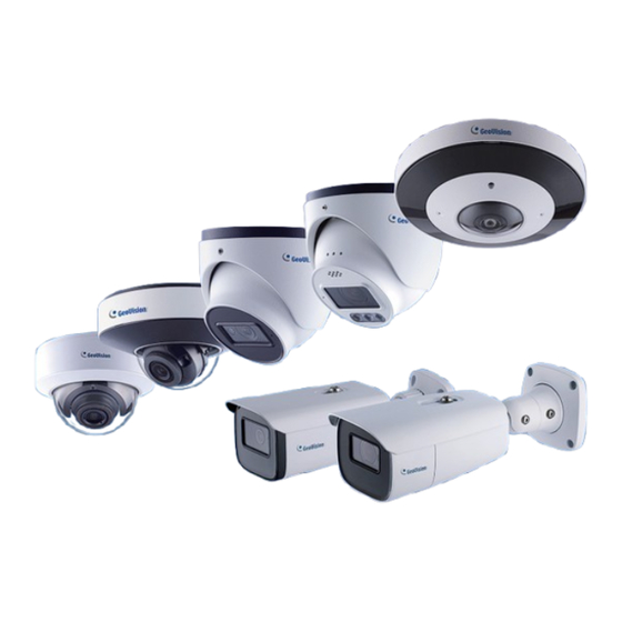
- Page 1 GV-Cloud IP Camera User's Manual GV-GBL4900 / GBL4911 GV-GDR4900 GV-GEB4900 GV-GEBF4911 GV-GFER6900 GV-GVD4910 Before attempting to connect or operate this product, please read these instructions carefully and save this manual for future use. GSERIES-UM-D...
- Page 2 GeoVision. Every effort has been made to ensure that the information in this manual is accurate. GeoVision, Inc. makes no expressed or implied warranty of any kind and assumes no responsibility for errors or omissions. No liability is assumed for incidental or consequential damages arising from the use of the information or products contained herein.
-
Page 3: Safety Instruction
Safety Instruction ⚫ This product is intended to be supplied by a Listed Power Unit, marked with 'Limited Power Source', 'LPS' on unit, output rated minimum 12V/2 A or POE 48V/ 350mA or AC24V (depending on models), no more than 2000m altitude of operation and Tma=60 Deg.C. - Page 4 Disclaimer With regard to the product with internet access, the use of product shall be wholly at your ⚫ own risks. Our company shall be irresponsible for abnormal operation, privacy leakage or other damages resulting from cyber attack, hacker attack, virus inspection, or other internet security risks;...
- Page 5 Regulatory Information FCC Information FCC compliance The products have been tested and found in compliance with the council FCC rules and regulations part 15 subpart B. These limits are designed to provide reasonable protection against harmful interference. This equipment generates uses and can radiate radio frequency energy and, if not installed and used in accordance with the instruction manual, may cause harmful interference to radio communication.
-
Page 6: Table Of Contents
Table of Contents Contents Safety Instruction ................................... i Contents ....................................iv Chapter 1 Introduction ..............................1 Chapter 2 Network Connection ............................2 2.1 LAN ..................................3 2.1.1 Access Through IP-Tool ..........................3 2.1.2 Directly Access Through IE Mode in Edge ....................5 2.2 WAN .................................. - Page 7 4.6.5 802.1x ............................... 100 4.6.6 RTSP ................................ 101 4.6.7 RTMP ................................ 102 4.6.8 UPnP ................................. 103 4.6.9 Email ................................. 104 4.6.10 FTP ................................. 105 4.6.11 HTTP POST ............................107 4.6.12 HTTPS ..............................108 4.6.13 QoS ................................. 109 4.6.14 TS Multicast ............................110 4.7 Security Configuration ............................
-
Page 8: Chapter 1 Introduction
Chapter 1 Introduction Surveillance Application... -
Page 9: Chapter 2 Network Connection
Chapter 2 Network Connection System Requirement For proper operation of the product, the following requirements should be met for your computer. Web browser: Edge / IE mode in Edge (plug-in required) / Chrome / Firefox / Safari *It is recommended to use the latest version of these web browsers. The menu display and operation of the camera may be slightly different by using the browser with plug-in (IE mode in Microsoft Edge) or without plug-in. -
Page 10: Lan
2.1 LAN In a LAN environment, there are two ways to access the IP camera: 1. through GV-IP Device Utility; 2. directly through IE mode in Microsoft Edge. 2.1.1 Access Through IP-Tool Network connection: By default, when the camera is connected to LAN with DHCP server, it is automatically assigned with a dynamic IP address. - Page 11 Type a new password and click OK. Click on its IP address again and select Webpage to open its Web interface. Type the set password on the login page and click Login. IMPORTANT: By default, the Administrator’s username is admin and cannot be modified. To change the password using GV-IP Device Utility, click on the camera’s IP address, and select Configure >...
-
Page 12: Directly Access Through Ie Mode In Edge
2.1.2 Directly Access Through IE Mode in Edge The default network settings are as shown below: IP address: 192.168.0.10 Subnet Mask: 255.255.255.0 Gateway: 192.168.226.1 HTTP: 80 Data port: 9008 Use the above default settings when logging in the camera for the first time. Directly connect the camera to the computer through network cable. - Page 13 Next, click the “Properties” button to set the network of the PC. Open the Web browser and enter the default address of the IP-camera. Follow directions to download and install the plug-in. Enter the default username and password on the login page and click “Login”.
-
Page 14: Wan
2.2 WAN Access through the router or virtual server Make sure the camera is connected to the local network and then log in the camera via LAN and go to Config→Network→Port menu to set the port number. Port Setup Go to Config →Network→TCP/IP menu to modify the IP address. IP Setup Go to the router’s management interface through IE mode in Microsoft Edge to forward the IP address and port of the camera in the “Virtual Server”. - Page 15 Access through PPPoE dial-up Network connection Access the camera through PPPoE auto dial-up. The setup steps are as follow: Go to Config→Network→Port menu to set the port number. Go to Config →Network→TCP/IP→PPPoE Config menu. Enable PPPoE and then enter the user name and password from your internet service provider. Go to Config →Network→DDNS menu.
-
Page 16: Chapter 3 Live View
Chapter 3 Live View After logging in, the following window will be shown. Note: Two-way audio, local recording, and the preview mode switch (real-time / balanced / fluent mode) are only supported in IE mode in Microsoft Edge. For GV-GBL4900 / GBL4911 / GDR4900 / GEB4900 / GEBF4911 / GVD4910: For GV-GFER4900: Before you view the live image, please set the stream mode and installation method as needed (see... - Page 17 Select live preview mode (only Sensor alarm indicator for GV-GFER6900) Original size Motion alarm indicator Color abnormal indicator (not Fit correct scale applicable to GV-GFER6900) Abnormal clarity indicator (not Adapt applicable to GV-GFER6900) Scene change indicator (not Full screen applicable to GV-GFER6900)
- Page 18 Loitering detection indicator PTZ control (not applicable to GV-GEBF4911 / GFER6900) Illegal parking detection Face Detection (not applicable indicator (not applicable to to GV-GFER6900) GV-GEBF4911 / GFER6900) Video metadata extraction Rule information display indicator (not applicable to GV-GFER6900) Note: 1. Those smart alarm indicators will flash only when the camera supports those functions and the corresponding events are enabled.
- Page 19 Live Preview Mode Click to select the live view mode. Note: The Live Preview Mode menu is only applicable to GV-GFER6900. Fisheye view mode: See the picture as shown above. Panoramic view mode: Fisheye+ 3PTZ view mode: Panoramic + 3PTZ view mode:...
- Page 20 4PTZ view mode: Requires switching the stream mode in the Fisheye Parameters settings 4PTZ fusion view mode: Displays a complete image formed by 4 smaller windows, none of which can be controlled via the PTZ panel. In Panoramic + 3PTZ view mode, Fisheye + 3PTZ view mode, or 4PTZ view mode, select a PTZ window and view the image from every direction by controlling the PTZ panel.
- Page 21 Speed adjustment Zoom out Zoom in Automatic cruise (only for Create and call cruise GV-GFER6900) (only for GV-GFER6900) Focus – (not applicable to Focus + (not applicable to GV-GFER6900) GV-GFER6900) Iris - (not applicable to Iris + (not applicable to...
- Page 22 To create a cruise (only for GV-GFER6900): Click as shown below. 2. Click to create a cruise. In the cruise creation window, enter the cruise name and then click “Add preset”. 3. In the preset adding window, select the preset name and time. Click “OK” to add this preset.
- Page 23 Rule Information Color Descriptions of Target Recognition box: Green box: detect human Purple box: detect motor vehicle Light blue box: detect non-motor vehicle (motorcycle/bicycle) Rule line or area color display: Rule line or area: blue Rule line or area after an event is triggered: turn from blue to red...
-
Page 24: Chapter 4 Network Camera Configuration
Chapter 4 Network Camera Configuration In the Webcam client, choose “Config” to go to the configuration interface. Note: Wherever applicable, click the “Save” button to save the settings. 4.1 System Configuration 4.1.1 Basic Information In the “Basic Information” interface, the system information of the device is listed. 4.1.2 Date and Time Go to Config→System→Date and Time. - Page 25 Note: The time zone of the camera and the computer must be the same. It is recommended to modify the time zone of the camera according to the time zone of the computer. If the time zone of the computer is modified, the current web client needs to be closed.
-
Page 26: Local Config
4.1.3 Local Config Go to Config→System→Local Config to set up the storage path of captured pictures and recorded videos on the local PC. There is also an option to enable or disable the bitrate display in the recorded files. Additionally, “Local smart snapshot storage” can be enabled or disabled here. If enabled, the captured pictures triggered by smart events (like line crossing detection, region entrance, etc.) will be saved to the local PC. -
Page 27: Storage
4.1.4 Storage Go to Config→System→Storage to go to the interface as shown below. 4.1.4.1 SD Card Management Click the “Format” button to format the SD card. All data will be cleared by clicking this button. Click the “Eject” button to stop writing data to SD card. Then the SD card can be ejected safely. - Page 28 4.1.4.2 Schedule Recording Settings Go to Config→System→Storage→Record to go to the interface as shown below. Set record stream, pre-record time, cycle writing. Pre Record Time: Set the time to record before the actual recording begins. Set schedule recording. Check “Enable Schedule Record” and set the schedule. Weekly Schedule Set the alarm time from Monday to Sunday for a single week.
- Page 29 4.1.4.3 Snapshot Settings Go to Config→System→Storage→Snapshot to go to the interface as shown below. Set the format, resolution and quality of the image saved on the SD card and the snapshot interval and quantity and the timing snapshot here. Snapshot Quantity: The number you set here is the maximum quantity of snapshots. The actual quantity of snapshots may be less than this number.
-
Page 30: Configuring Fisheye Parameters
Before viewing the live image, please go to Config→System→Fisheye Parameters menu to set the stream mode and installation method. Note: The Fisheye Parameters menu is only applicable to GV-GFER6900. Stream Mode: Fisheye, Panoramic View, Fisheye + Panoramic view + 3PTZ, Fisheye + 4PTZ, and Fisheye + 4PTZ Fusion modes are optional. -
Page 31: Image Configuration
4.2 Image Configuration 4.2.1 Display Configuration Go to Image→Display Settings interface as shown below. The image’s brightness, contrast, hue and saturation and so on for common, day and night mode can be set up separately. The image effect can be quickly seen by switching the configuration file. Brightness: Set the brightness level of the camera’s image. - Page 32 ⚫ HLC: Lowers the brightness of the entire image by suppressing the brightness of the image’s bright area and reducing the size of the halo area. ⚫ BLC: If enabled, the auto exposure will activate according to the scene so that the object of the image in the darkest area will be seen clearly.
- Page 33 Frequency: 50 Hz and 60 Hz can be optional. Corridor Pattern (not applicable to GV-GFER6900): Corridor viewing modes can be used for situations such as long hallways. 0, 90, 180 and 270 are available. The default value is 0.
-
Page 34: Video / Audio Configuration
4.2.2 Video / Audio Configuration Go to Image→Video / Audio interface as shown below. In this interface, set the resolution, frame rate, bitrate type, video quality and so on subject to the actual network condition. Note: The video stream parameters of different camera series may be different. The following pictures and descriptions are for reference only. - Page 35 bandwidth usage. However, if the value is set too high, and there is a high frequency of movement in the video, there is a risk of frame skipping. Video Compression: MJPEG, H264+, H264, H265 or H265+ are applicable. MJPEG is not available for main stream.
- Page 36 Audio Output (not applicable to GV-GFER6900): Talkback, warning or auto can be optional. If “Talkback” is selected, the audio output will be used to output sound for two-way talk. If “Warning” is selected, the audio output will be used to output the pre-defined audio alarm. If “Auto”...
-
Page 37: Osd Configuration
4.2.3 OSD Configuration Go to Image→OSD interface as shown below. For GV-GEBF4911 Set time stamp, device name, OSD content and picture overlap here. After enabling the corresponding display and entering the content, drag them to change their position. Then click the “Save”... - Page 38 Then click “Open” to upload the overlap picture. The pixel of the image shall not exceed 200*200, or it cannot be uploaded. Note: For GV-GFER6900, the OSD information can only be overlaid on the Fisheye channel.
-
Page 39: Video Mask
4.2.4 Video Mask Go to Image→Video Mask interface as shown below. A maximum of 4 zones can be set up. To set up video mask: Enable video mask. Click the “Draw Area” button and then drag the mouse to draw the video mask area. Click the “Save”... -
Page 40: Roi Configuration
4.2.5 ROI Configuration Go to Image→ROI Config interface as shown below. An area in the image can be set as a region of interest. This area will have a higher bitrate than the rest of the image, resulting in better image quality for the identified area. Check “Enable”... -
Page 41: Lens Control
4.2.6 Lens Control This function is only available for the model with motorized zoom lens. Within this section, zoom and focus can be controlled. If the image is out of focus after a manual adjustment, one key focus can be used to set the focus automatically. Go to Config→Image→ Zoom/Focus interface to set. -
Page 42: Alarm Configuration
4.3 Alarm Configuration 4.3.1 Motion Detection Go to Alarm→Motion Detection to set motion detection alarm. For GV-GEBF4911 / GFER6900 1. Check “Enable” check box to activate motion based alarms. If unchecked, the camera will not send out any signals to trigger motion-based recording to the NVR or CMS, even if there is motion in the video. - Page 43 2. Set motion detection area and sensitivity. Click the “Area and Sensitivity” tab to go to the interface as shown below. Move the “Sensitivity” scroll bar to set the sensitivity. Higher sensitivity value means that motion will be triggered more easily. Select “Add”...
- Page 44 For GV-GBL4900 / GBL4911 / GDR4900 / GEB4900 / GVD4910 1. Check “Enable” check box to activate motion-based alarms. If unchecked, the camera will not send out any signals to trigger motion-based recording to the NVR or CMS, even if there is motion in the video.
-
Page 45: Exception Alarm
4.3.2 Exception Alarm ⚫ SD Card Full Go to Config→Alarm→Exception Alarm→SD Card Full. Click “Enable”. Set the alarm holding time and alarm trigger options. The setup steps are the same as motion detection. Please refer to 4.3.1 Motion Detection for details. ⚫... - Page 46 ⚫ IP Address Conflict Go to Config→Alarm→Exception Alarm→IP Address Collision as shown below. Click “Enable” and set the alarm holding time. Trigger alarm out. When the IP address of the camera conflicts with the IP address of other devices, the system will trigger the alarm out. ⚫...
-
Page 47: Alarm In
4.3.3 Alarm In To set sensor alarm (alarm in): Go to Config→Alarm→Alarm In interface as shown below. GV-GEBF4911 / GFER6900 GV-GBL4900 / GBL4911 / GDR4900 / GEB4900 / GVD4910 Click “Enable” and set the alarm type, alarm holding time and sensor name. Set alarm trigger options. -
Page 48: Alarm Out
4.3.4 Alarm Out Go to Config→Alarm→Alarm Out. Alarm Out ID: The alarm out can be set respectively by selecting alarm out ID. Alarm Out Mode: Alarm linkage, manual operation, day/night switch linkage and timing are optional. Alarm Linkage: Having selected this mode, select alarm out name, alarm holding time at the “Alarm Holding Time”... -
Page 49: Alarm Server
4.3.6 Audio Alarm Go to Alarm→Audio Alarm interface as shown below. Enable audio alarm. If disabled, the warning sound will not be uttered by clicking the icon in the live view interface. Note: The Audio Alarm function is not applicable to GV-GFER6900. - Page 50 1. Select the warning voice. If you want to customize the voice, you can chose “Customize”. Click “Browse” to choose the audio file you to upload and then enter the audio name. Finally, click “Upload” to upload the audio file. Note that the format of the audio file must meet the requirement, or it will not be uploaded.
-
Page 51: Light Alarm
4.3.7 Light Alarm Go to Alarm→Audio Alarm interface as shown below. Note: The Audio Alarm function is only applicable to GV-GEBF4911. Enable light alarm as needed. If it is disabled, the flashing light will not be turned on by clicking in the live view interface. -
Page 52: Audio Exception
4.3.9 Audio Exception Alarms will be triggered when the abnormal sound is detected in the surveillance scene, such as the sudden increase/decrease of the sound intensity. Note: The Audio Exception function is only applicable to GV-GBL4900 / GBL4911 / GDR4900 / GEB4900 / GVD4910. To set audio exception detection: Go to Alarm→Audio Exception interface as shown below. - Page 53 Real-time audio graphic: Red wavy line stands for the current detected sound intensity. Navy blue line stands for the environment (background) sound intensity. Green line stands for the sound intensity threshold. In order to reduce false alarm, it is recommended to set the sensitivity and sound intensity threshold according to the real-time audio graphic.
-
Page 54: Event Configuration
4.4 Event Configuration For more accuracy, here are some recommendations for installation. Cameras should be installed on stable surfaces, as vibrations can affect the accuracy of ⚫ detection. Avoid pointing the camera at the reflective surfaces (like shiny floors, mirrors, glass, lake ⚫... - Page 55 After a successful reboot, the corresponding event will be displayed. Configure as needed. For GV-GFER6900: Only 1 AI event can be enabled at a time: smart events only, as GV-GFER6900 does not support face events. Only 1 smart event is supported when connected to GV-Cloud VMS or GV-Center V2.
-
Page 56: Object Abandoned / Missing
GV-GBL4900 / GBL4911 / GDR4900 / GEB4900 / GVD4910 Note: The Object Abandoned / Missing function is not applicable to GV-GFER6900. Enable abandoned/missing object detection and then select the detection type. Enable Abandoned Object Detection: Alarms will be triggered if there are items left in the pre-defined area. - Page 57 For GV-GEBF4911 Click “Save” button to save the settings. Set the alarm area of the abandoned/missing object detection. Click the “Area” tab to go to the interface as shown below. Set the alarm area number and then enter the desired alarm area name. Only one alarm area can be added.
- Page 58 ※ The configuration requirements of camera and surrounding areas The range of the detection object should occupy from 1/50 to 1/3 of the entire image. The detection time of objects in the camera shall be from 3 to 5 seconds. The defined area cannot be covered frequently and continuously (like people and traffic flow).
-
Page 59: Video Exception
This function can detect changes in the surveillance environment affected by the external factors. To set exception detection: Note: The Video Exception function is not applicable to GV-GFER6900. For GV-GEBF4911 Go to Config→Event→Video Exception interface as shown below. Enable the applicable detection that’s desired. - Page 60 Set the sensitivity of the exception detection. Click “Sensitivity” tab to go to the interface as shown below. Drag the slider to set the sensitivity value or directly enter the sensitivity value in the textbox. Click “Save” button to save the settings. The sensitivity value of Scene Change Detection: The higher the value is, the more sensitive the system responds to the amplitude of the scene change.
- Page 61 For GV-GBL4900 / GBL4911 / GDR4900 / GEB4900 / GVD4910 Go to Config→Alarm→Video Exception interface as shown below. Enable the applicable detection that’s desired. Scene Change Detection: Alarms will be triggered if the scene of the monitor video has changed. Video Blur Detection: Alarms will be triggered if the video becomes blurry.
-
Page 62: Line Crossing
4.4.3 Line Crossing Line Crossing: Alarms will be triggered if the target crosses the pre-defined alarm lines. Go to Config→Event→Line Crossing interface as shown below. GV-GEBF4911 / GFER6900 GV-GBL4900 / GBL4911 / GDR4900 / GEB4900 / GVD4910 Enable line crossing alarm and select the snapshot type and the detection target. Save Original Picture to SD Card: If it is enabled, the detected original pictures will be captured and saved to the SD card when the targets cross the alarm line. - Page 63 Set area and sensitivity of the line crossing alarm. Click the “Area and Sensitivity” tab (“Area” tab for GV-GFER6900) to go to the interface as shown below. Set the alarm line number and direction. Up to 4 lines can be added. Multiple lines cannot be added simultaneously.
- Page 64 For GV-GBL4900 / GBL4911 / GDR4900 / GEB4900 / GVD4910 Set alarm lines and target size filter for line crossing detection. Set the alarm line number and direction. Four lines can be added. Multiple lines cannot be added simultaneously. Direction: A←→B, A→B and A←B optional. This indicates the direction of the intruder who crosses over the alarm line that would trigger the alarm.
- Page 65 4. Click “Save” button to save the settings. 5. Set the schedule of the line crossing detection. The setup steps of schedule are the same as the motion detection schedule settings (See 4.1.4.2 Schedule Recording Settings). 6. Click “Linkage” to configure the alarm linkage items. The setup steps are the same as motion detection.
- Page 66 Correct example The target recognition box meets the requirements of the minimum size. The yellow box stands for the minimum recognition size. The green box stands for the set target box. Wrong example The yellow box stands for the minimum recognition size. The green box stands for the set target box.
- Page 67 Installation suggestion: Outdoor mounting: The optimal detection distance varies due to different focal length. Please refer to the following table. Human/Motorcycle/Bicycle Motor Vehicle Focal Installation Maximum Optimal Maximum Optimal Length Height(m) Distance(m) Distance(m) Distance(m) Distance(m) 2.8 mm 3-10 10-15 3.6 mm 3-10 5-10 15-20...
-
Page 68: Region Entrance
4.4.4 Region Entrance Region Entrance: Alarms will be triggered if the target enters the pre-defined areas. Go to Config→Event→Region Entrance interface as shown below. GV-GEBF4911 / GFER6900 GV-GBL4900 / GBL4911 / GDR4900 / GEB4900 / GVD4910 Enable region entrance detection and select the snapshot type and the detection target. Save Original Picture to SD Card: If it is enabled, the detected original pictures will be captured and saved to the SD card when the targets intrude into the pre-defined areas. - Page 69 Push target trajectory with a persistent connection (for GV-GBL4900 / GBL4911 / GDR4900 / GEB4900 / GFER6900 / GVD4910): Push target trajectory (moving coordinate) to API test tool with a persistent connection. If enabled, the system will push the target trajectory upon detecting a target. If disabled, the system will push the target trajectory only when triggering line crossing alarm.
- Page 70 Set the schedule of the region entrance detection. The setup steps of schedule are the same as the motion detection schedule settings (See 4.1.4.2 Schedule Recording Settings). Click “Linkage” to configure the alarm linkage items. The setup steps are the same as motion detection.
-
Page 71: Region Exiting
4.4.5 Region Exiting Region Exiting: Alarms will be triggered if the target exits from the pre-defined areas. Go to Config→Event→Region Exiting interface as shown below. GV-GEBF4911 / GFER6900 GV-GBL4900 / GBL4911 / GDR4900 / GEB4900 / GVD4910 Enable region exiting detection and select the snapshot type and the detection target. Set the alarm holding time and alarm trigger options. -
Page 72: Target Counting By Line
4.4.6 Target Counting by Line This function is to calculate the number of the people or vehicles crossing the alarm line through detecting, tracking and counting the shapes of the people or vehicles. Go to Config→Event→Target Counting by Line as shown below. GV-GEBF4911 / GFER6900 GV-GBL4900 / GBL4911 / GDR4900 / GEB4900 / GVD4910... - Page 73 4.1.4.2 Schedule Recording Settings). View the statistical information in the live view interface. (For GV-GFER6900, click the Fisheye live preview mode in the live view interface.) View the statistical information of target counting by line. Click “Statistics” to enter the following interface.
- Page 74 Select the start time and then click “Count”. Then the counting result will display in the statistic result area. Click Table or Chart to display the result in different way. GV-GBL4900 / GBL4911 / GDR4900 / GEB4900 / GVD4910 Set the alarm holding time. Set alarm lines and target size filter.
- Page 75 Click “Save” button to save the settings. Set the schedule of the target counting by line. The setup steps of schedule are the same as the motion detection schedule settings (See 4.1.4.2 Schedule Recording Settings). Click “Linkage” to configure the alarm linkage items. The setup steps are the same as motion detection.
- Page 76 Select the start time and then click “Count”. Then the counting result will display in the statistic result area. Click Table or Statistics to display the result in different way. ※ Configuration requirements of camera and surrounding area The requirements are similar to line crossing detection. Please refer to Configuration requirements of camera and surrounding area in 4.4.3 Line Crossing for details.
-
Page 77: Target Counting By Area
Go to Config→Event→Target Counting by Area as shown below. GV-GEBF4911 GV-GBL4900 / GBL4911 / GDR4900 / GEB4900 / GVD4910 Note: The Target Counting by Area function is not applicable to GV-GFER6900. Enable target counting by area, select the snapshot type, the detection target, counting reset. For GV-GEBF4911 Set up alarm triggers. - Page 78 Select the alarm area number on the right side. Only one alarm area can be added. Click the “Draw Area” button and then click around the area where you want to set as the alarm area in the image on the left side (the alarm area should be a closed area). Click the “Stop Draw”...
- Page 79 Only for GV-GBL4900 / GBL4911 / GDR4900 / GEB4900 / GVD4910 ○ 1 : the statistical number of target counting by area ○ 2 : the statistical number of target counting by line Each line of the above OSD information (including OSD content, colon, slashes and images) cannot exceed 37 characters, or some data will not be displayed completely.
-
Page 80: Region Intrusion
4.4.8 Region Intrusion Region Intrusion: Alarms will be triggered if the target intrudes into the pre-defined areas. This function can be applicable to important supervision places, danger areas and prohibited areas, like military administrative zones, high danger areas, no man’s areas, etc. Go to Config→Event→Region Intrusion interface as shown below. - Page 81 6. Set the schedule of the region intrusion detection. The setup steps of the schedule are the same as schedule recording setup (See 4.1.4.2 Schedule Recording Settings). 7. In the live view interface, click “Fisheye” (ceiling mounting mode) to view region intrusion detection. (This step is only applicable to GV-GFER6900)
- Page 82 For GV-GBL4900 / GBL4911 / GDR4900 / GEB4900 / GVD4910 Set alarm areas and target size filter for region intrusion detection. Set the alarm area number. Four alarm areas can be added. Click the “Draw Area” button and then click around the area where you want to set as the alarm area in the image (the alarm area should be a closed area).
-
Page 83: Face Detection
Face detection function is to detect the face appearing in the surveillance scene. Alarms will be triggered when a face is detected. Note: The Face Detection function is not applicable to GV-GFER6900. The setting steps are as follows: For GV-GEBF4911... - Page 84 Enable the face detection function. Save Source Information to SD Card: if checked, the whole picture will be saved to the local PC or SD card when detecting a face. Save Face Information to SD Card: if checked, the captured face picture will be saved to the local PC or SD card when detecting a face.
- Page 85 Advanced settings. Choose the snapshot interval and number as needed to avoid capturing multiple similar pictures in a very short period of time. Snapshot Interval: If 5 seconds is selected, the camera will capture the same target once every 5 seconds during its continuous tracking period. Snapshot Number: If the snapshot number is enabled and set (eg.
- Page 86 For GV-GBL4900 / GBL4911 / GDR4900 / GEB4900 / GVD4910 Click Config→Event→Enable Event. Select the face event and then save the setting. After the camera restarts successfully, you can view the face detection menu. Go to Config→Event→Face Detection as shown below. Enable the face detection function.
- Page 87 Advanced settings. Choose the snapshot interval and number as needed to avoid capturing multiple similar pictures in a very short period of time. Deduplication Period: If 30 seconds is selected, the camera will capture the same target once every 30 seconds during its continuous tracking period. Snapshot Number: If the snapshot number is enabled and set (eg.
- Page 88 Face Capture View After enabling face detection function, return to the live view interface. Click to go to the following interface. When there are faces detected, the face pictures will be listed on the right. The features of captured faces also can be displayed, such as gender, whether to wear a mask, whether to wear glasses, age group, etc.
-
Page 89: Crowd Density
This function can detect the density of the people in a specified area (like square, supermarket). Go to Config→Event→Crowd Density as shown below. Note: The Crowd Density function is only applicable to GV-GFER6900. 1. Enable the crowd density detection. 2. Set “Refresh Frequency”, “Density Alarm Threshold” and “Alarm Holding Time”. - Page 90 5. Set the schedule of the crowd density detection. The setup steps of the schedule are the same as schedule recording setup (See 4.1.4.2 Schedule Recording Settings). Note: The camera only can roughly calculate the crowd density through detecting the human faces.
-
Page 91: Heat Map
For GV-GEBF4911 / GFER6900 1. Enable Heat Map, set snapshot type and detection target type as needed. Note: For GV-GFER6900: The Motor Vehicle and Motorcycle/Bicycle targets are not applicable. The Heat Map function is only available when the installation method is set to “Ceiling”. - Page 92 Click “Count” to view the heat map as shown below. The default heat map is people flow data display. Click “Motor Vehicle” or “Non-motor Vehicle” to view the corresponding data. (People flow data is the only display option for GV-GFER6900.)
- Page 93 For GV-GBL4900 / GBL4911 / GDR4900 / GEB4900 / GVD4910 1. Enable Heat Map, set snapshot type and detection target type as needed. 2. Set heat map display area and target size filter. Up to 4 areas can be set. Click the “Draw Area”...
-
Page 94: Video Metadata
GV-GBL4900 / GBL4911 / GDR4900 / GEB4900 / GVD4910 Note: The Video Metadata function is not applicable to GV-GFER6900. Enable video metadata and select the snapshot type and the detection target. Save Original Picture to SD Card: If it is enabled, the detected original pictures will be captured and saved to the SD card when the targets enter the pre-defined areas. - Page 95 Detection Area: 4 detection areas can be set. Targets that enter in the pre-defined detection area will be counted and captured. Blocked Area: 4 blocked areas can be set. Targets that enter in the pre-defined blocked area will not be counted and captured. You need to set the detection area and blocked area separately.
- Page 96 Video Metadata View In the live interface, click to view the following smart snapshots. Human information will be shown on the right panel. Motor vehicle and non-motor vehicle information will be shown on the left panel. Click the captured picture to view the detailed information, including original picture, target picture and detailed attributes.
-
Page 97: Loitering Detection
4.4.13 Loitering Detection Loitering Detection: when someone entering and loitering in a pre-defined area exceeds the threshold, alarms will be triggered until the object leaves this area. Note: The Loitering Detection function is only applicable to GV-GBL4900 / GBL4911 / GDR4900 / GEB4900 / GVD4910. - Page 98 Target size filter setup: The setup steps of the target size filter are the same as line crossing target size filter setup (See 4.4.3 Line Crossing for details). 4. Set the schedule of the target counting by line. The setup steps of schedule are the same as the motion detection schedule settings (See 4.1.4.2 Schedule Recording Settings).
-
Page 99: Illegal Parking Detection
4.4.14 Illegal Parking Detection Illegal Parking Detection: when a vehicle (like a car, truck, motorcycle, etc.) staying in a no-parking zone exceeds the threshold, alarms will be triggered until the vehicle is driven away. Note: The Illegal Parking Detection function is only applicable to GV-GBL4900 / GBL4911 / GDR4900 / GEB4900 / GVD4910. - Page 100 Click the “Draw Area” button and then click around the area where you want to set as the alarm area in the image (the alarm area should be a closed area). Click the “Clear” button to delete the alarm area. Click the “Save” button to save the settings. Target size filter setup: The setup steps of the target size filter are the same as line crossing target size filter setup (See 4.4.3 Line Crossing...
-
Page 101: Service
4.5 Service 4.5.1 GV-Cloud VMS The GV-Cloud VMS service is a cloud-based data center and video surveillance solution. Thousands of on-site videos, alarm devices, and AI events can be monitored and managed from a single platform. With GV-Cloud VMS, you can easily search for events and watch live streams or recordings from anywhere using a web browser. -
Page 102: Gv-Center V2
4.5.2 GV-Center V2 GV-Center V2 is a Central Monitoring System (CMS) software that allows users to monitor, receive and record events from IP cameras and surveillance systems on a single platform. During alert events, GV-Center V2 receives live view and messages with attached recordings, allowing users to track any abnormalities on the premises. -
Page 103: Network Configuration
4.6 Network Configuration 4.6.1 TCP/IP Go to Config→Network→TCP/IP interface as shown below. There are two ways for network connection. Use IP address (take IPv4 for example): There are two options for IP setup: obtain an IP address automatically by DHCP and use the following IP address. Please choose one of the options as needed. -
Page 104: Port
4.6.2 Port Go to Config→Network→Port interface as shown below. HTTP port, Data port and RTSP port can be set. HTTP Port: The default HTTP port is 80. It can be changed to any port which is not occupied. HTTPS Port: The default HTTPs port is 443. It can be changed to any port which is not occupied. -
Page 105: Ddns
4.6.3 DDNS If the camera is set up with a DHCP connection, DDNS should be set for the internet. Go to Config→Network→ DDNS. Apply for a domain name. Take www.dvrdyndns.com for example. Enter www.dvrdydns.com in the address bar of IE mode in Microsoft Edge to visit its website. -
Page 106: Snmp
4.6.4 SNMP To get camera status, parameters and alarm information and remotely manage the camera, the SNMP function can be used. Before using SNMP, please install an SNMP management tool and set the parameters of the SNMP, such as SNMP port, trap address. Go to Config→Network→SNMP. -
Page 107: 100
4.6.5 802.1x If it is enabled, the camera’s data can be protected. When the camera is connected to the network protected by the IEEE 802.1x, user authentication is needed. To use this function, the camera shall be connected to a switch supporting 802.1x protocol. The switch can be reckoned as an authentication system to identify the device in a local network. -
Page 108: Rtsp
4.6.6 RTSP Go to Config→Network→RTSP. For GV-GBL4900 / GBL4911 / GDR4900 / GEB4900 / GFER6900 / GVD4910: Click “Edit” to start the setup. Select “Enable” to enable the RTSP function. Port: Access port of the streaming media. The default number is 554. RTSP Address: The RTSP address (unicast) format that can be used to play the stream in a media player. -
Page 109: Rtmp
4.6.7 RTMP You can access the third-party (like YouTube) to realize video live view through RTMP protocol. Go to Config→Network→RTMP. For GV-GBL4900 / GBL4911 / GDR4900 / GEB4900 / GFER6900 / GVD4910: Click “Edit” to start the setup. Check “Enable”, select stream type, set the reconnection time after timeout and server address as needed. -
Page 110: Upnp
4.6.8 UPnP If this function is enabled, the camera can be quickly accessed through the LAN. Go to Config→Network→UPnP. Enable UPNP and then enter UPnP name. -
Page 111: Email
4.6.9 Email If you need to trigger Email when an alarm happens or IP address is changed, please set the Email here first. Go to Config→Network →Email. For GV-GBL4900 / GBL4911 / GDR4900 / GEB4900 / GFER6900 / GVD4911, click “Edit and Test”... -
Page 112: Ftp
4.6.10 FTP After an FTP server is set up, captured pictures from events will be uploaded to the FTP server. 1. Go to Config→Network →FTP. 2. For GV-GBL4900 / GBL4911 / GDR4900 / GEB4900 / GFER6900 / GVD4910: Click “Edit and Test”... - Page 113 MOTION Motion Detection SENSOR Sensor Alarm TRIPWIRE Line Crossing Detection PERIMETER Region Intrusion Detection Object Abandoned/Missing Video Exception Face Detection AOIENTRY Region Entrance AOILEAVE Region Exiting PASSLINECOUNT Target Counting by Line TRAFFIC Target Counting by Area LOITER Loitering Detection Illegal Parking Detection SDFULL SD Full SDERROR...
-
Page 114: Http Post
4.6.11 HTTP POST For GV-GBL4900 / GBL4911 / GDR4900 / GEB4900 / GFER6900 / GVD4910: Click “Edit” to start the setup. Go to Config→Network →HTTP POST interface. Check “Enable”, select protocol type and then set the server address (IP address/domain name), server port and heartbeat interval. -
Page 115: Https
4.6.12 HTTPS HTTPs provides authentication of the web site and protects user privacy. Go to Config →Network→HTTPS as shown below. There is a certificate installed by default as shown above. Enable this function and save it. Then the camera can be accessed by entering https://IP: https port via the web browser (e.g., https://192.168.226.201:443). -
Page 116: Qos
4.6.13 QoS QoS (Quality of Service) function is used to provide different quality of services for different network applications. With the deficient bandwidth, the router or switch will sort the data streams and transfer them according to their priority to solve the network delay and network congestion by using this function. -
Page 117: Ts Multicast
4.6.14 TS Multicast By using transport stream multicast (TS Multicast), multiple users can view the video image simultaneously even if there is not enough bandwidth. Note: TS Multicast is only applicable to GV-GEBF4911. Multicast address: the multicast IP address of Main Stream/Sub Stream/Third Stream ranges from 224.0.0.0 to 239.255.255.255. -
Page 118: Security Configuration
4.7 Security Configuration 4.7.1 User Configuration Go to Config→Security→User interface as shown below. Add user: Click the “Add” button to pop up the following textbox. Enter user name in the “User Name” textbox. Enter the password in the “Password” and “Confirm Password” textbox. Please set the password according to the requirement of the password security level (Go to Config→Security→Security Management→Password Security interface to set the security level). - Page 119 Modify user: Select a user to modify password in the user configuration list box. The “Edit user” dialog box pops up by clicking the “Modify” button. Enter the old password of the user in the “Old Password” text box. Enter the new password in the “New password” and “Confirm Password” text box. Select the user permissions for advanced or normal user.
-
Page 120: Online User
4.7.2 Online User Go to Config→Security→Online User to view the user who is viewing the live video. An administrator user can kick out all the other users (including other administrators). 4.7.3 Block and Allow Lists Go to Config→Security→Block and Allow Lists as shown below. The setup steps are as follows: Check the “Enable address filtering”... -
Page 121: Security Management
4.7.4 Security Management Go to Config→Security→Security Management as shown below. ⚫ Security Service In order to prevent against malicious password unlocking, “locking once illegal login” function can be enabled here. If this function is enabled, login failure after trying six times will make the login interface locked. -
Page 122: Maintenance Configuration
4.8 Maintenance Configuration 4.8.1 Backup and Restore Go to Config→Maintenance→Backup and Restore. GV-GEBF4911 Import & Export Settings ⚫ Configuration settings of the camera can be exported form a camera into another camera. Click “Browse” to select the save path for import or export information on the PC. Click the “Import Setting”... - Page 123 GV-GBL4900 / GBL4911 / GDR4900 / GEB4900 / GFER6900 / GVD4910 Import & Export Settings ⚫ Configuration settings of the camera can be exported form a camera into another camera. Click “Browse” to select the save path for import or export information on the PC. Click the “Import Setting”...
-
Page 124: Reboot
4.8.2 Reboot Go to Config→Maintenance→Reboot. Click the “Reboot” button to reboot the device. Timed Reboot Setting: If necessary, the camera can be set up to reboot on a time interval. Enable “Time Settings”, set the date and time and then click the “Save” button to save the settings. 4.8.3 Upgrade Go to Config→Maintenance→Upgrade. -
Page 125: Operation Log
4.8.4 Operation Log To query and export log: Go to Config→Maintenance→Operation Log. Select the main type, sub type, start and end time. Click “Search” to view the operation log. Click “Export” to export the operation log. 4.8.5 Advanced The software photosensitive 2.0 function is used to enable software light sensitivity mode depending on the setup environment. -
Page 126: Chapter 5 Search
Chapter 5 Search 5.1 Image Search Click Search to go to the interface as shown below. Images that are saved on the SD card can be found here. Note: Local images can only be searched in IE mode in Microsoft Edge. - Page 127 For GV-GEBF4911 ⚫ Local Image Search 1. Choose “Picture”—“Local”. 2. Set time: Select date and choose the start and end time. 3. Click to search the images. 4. Double click a file name in the list to view the captured photos. Click to return to the previous interface.
- Page 128 GV-GBL4900 / GBL4911 / GDR4900 / GEB4900 / GFER6900 / GVD4910 ⚫ SD Card Image Search 1. Choose “Picture”. 2. Set time: Select date and choose the start and end time. 3. Choose the alarm events at the bottom of the interface. 4.
- Page 129 The descriptions of the buttons are shown as follows. Icon Description Icon Description Close: Select an image Close all: Click this button to and click this button to close all images. close the image. Save: Click this button to Save All: Click this button to select the path for saving select the path for saving all the image on the PC.
-
Page 130: Video Search
5.2 Video Search Click Search to go to the interface as shown below. Videos were recorded locally to the PC / save in the SD card can be played in this interface. Note: Local videos can only be searched in IE mode in Microsoft Edge. For GV-GEBF4911 ⚫... - Page 131 ⚫ SD Card Video Search 1. Choose “Record”—“SD Card”. 2. Set search time: Select the date and choose the start and end time. 3. Click to search the images. 4. Select the alarm events at the bottom of the interface. 5.
- Page 132 For GV-GBL4900 / GBL4911 / GDR4900 / GEB4900 / GFER6900 / GVD4910 1. Choose “Record”. 2. Set search time: Select the date and choose the start and end time. 3. Click to search the images. 4. Select the alarm events at the bottom of the interface. 5.
- Page 133 Icon Description Icon Description Play button. After pausing the video, click this button Pause button to continue playing. Stop button Speed down Speed up Watermark display Enable / disable audio; drag the slider to adjust the volume after enabling audio. Note: can only be displayed in the above interface via IE mode in Microsoft Edge.
-
Page 134: Appendix
Appendix Appendix 1 Troubleshooting How to find the password? A: The password for admin can be reset through “Edit Safety Question” function. Click “Forget Password?” on the login page and enter the corresponding answer of the selected question in the popup window. After you correctly answer all questions, you can reset the password for admin. - Page 135 B. Other plug-ins or anti-virus blocks the plug-in. Please uninstall or close them. No sound can be heard. A: Audio input device is not connected. Please connect and try again. B: Audio function is not enabled at the corresponding channel. Please enable this function. What’s the Web/ONVIF/RTSP connection limit? A maximum of 6 connections of Web/ONVIF/RTSP is supported.
-
Page 136: Appendix 2 Configuration Requirements And Surrounding Area
Appendix 2 Configuration Requirements and Surrounding Area Auto-focusing function should not be enabled. Enabling auto-focusing may cause significant changes in the picture, leading to temporary algorithm interruption. Try to avoid excessive obstruction from trees, while also avoiding excessive variations in lighting conditions in the scene, such as frequent and excessive car headlights, etc., to improve the accuracy of intelligent functions. - Page 137 Correct example: The target meets the minimum size requirements. The yellow box in the image represents the minimum detection box. Incorrect example: The target does not meet the minimum size requirements. The yellow box in the image represents the minimum detection box.
- Page 138 Installation suggestion: Outdoor mounting: The optimal detection distance varies due to different focal length. Please refer to the following table. Human/Motorcycle/Bicycle Motor Vehicle Focal Installation Maximum Optimal Maximum Optimal Length Height (m) Distance Distance Distance Distance 2.8 mm 3-10 10-15 3.6 mm 3-10 5-10...
Need help?
Do you have a question about the GV-GFER6900 and is the answer not in the manual?
Questions and answers