Table of Contents
Advertisement
Quick Links
6
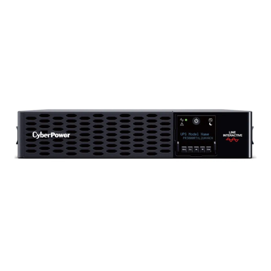
FEATURES
1. Power Switch
2. Toolless Battery Access Door
(behind faceplate)
3. Front Panel Access Tabs
(behind faceplate)
4. LCD Module
5. Faceplate
4241 12th Avenue East, Suite 400 | Shakopee, MN 55379 | CyberPowerSystems.com
YOUR ULTIMATE ALLY IN POWER
SMART APP SINEWAVE UPS SERIES
PR2200RTXL2UHVACN / PR3000RTXL2UHVACN
USER MANUAL
7
Cyber Power Systems (USA), Inc.
5
18
17
6. Battery Backed and Surge
Protected Outlets
7. Output Circuit Breaker
8. SNMP/HTTP Network Slot
9. Cloud Monitoring (Ethernet Port)
10. Input Circuit Breaker
11. AC Inlet
12. BM Port
13. Dry Contact
14. Serial Port
15. USB Port
16. EPO/ROO Port
17. TVSS Screw
18. Extended Battery Module
Connector Socket
1
2
4
8
9
10
11
16
15
14
13
12
3
Advertisement
Table of Contents

Subscribe to Our Youtube Channel
Related Manuals for Cyber Power Smart App Sinewave PR2200RTXL2UHVACN


Summary of Contents for Cyber Power Smart App Sinewave PR2200RTXL2UHVACN
- Page 1 12. BM Port 13. Dry Contact 14. Serial Port 15. USB Port 16. EPO/ROO Port 17. TVSS Screw 18. Extended Battery Module Connector Socket Cyber Power Systems (USA), Inc. 4241 12th Avenue East, Suite 400 | Shakopee, MN 55379 | CyberPowerSystems.com...
-
Page 2: Product Registration
PRODUCT REGISTRATION Thank you for purchasing a CyberPower product. Please take a few minutes to register your product at www.cyberpowersystems.com/registration. Registration certifies your product’s warranty, confirms your ownership in the event of a product loss or theft and entitles you to free technical support. -
Page 3: Installing Your Ups System
INSTALLING YOUR UPS SYSTEM UNPACKING PFC compatible for safeguarding mission- critical servers, telecom equipment, VoIP Inspect the UPS upon receipt. and internetworking hardware that require The box should contain the following: seamless sine wave power. Its full Automatic (a) UPS unit Voltage Regulation (AVR) boost/buck (b) Faceplate technology delivers a consistent and clean... - Page 4 INSTALLING YOUR UPS SYSTEM - CONTINUED INSTALLATION The product is designed for tower installation and rack installation for 2-post rack and 4-post rack. Read and follow the procedures thoroughly before and during your installation of the product. The installation videos are available online. Scan the QR code below for detailed information.
-
Page 5: Basic Operation
INSTALLING YOUR UPS SYSTEM - CONTINUED Tower Installation Attach the brackets to the baseplate with the provided M4 flat head screws. 2. Remove the faceplate and rotate the LCD module, then re-install the faceplate. 3. Screw the rubber feet with provided M4 round head screws and then put the UPS onto the assembled tower stand. -
Page 6: Cleaning And Maintenance
BASIC OPERATION - CONTINUED E. To prevent the risk of electric shock, follow When there is no utility, you need to the steps to ground the UPS: follow below procedures to turn on the UPS. Slightly press the power switch on (a) Connect a ground wire to the TVSS LCD module once. -
Page 7: Network Operation
NETWORK OPERATION Local Monitoring Connect either the USB cable or Serial cable to the corresponding port on the UPS and on the computer with PowerPanel Business software installed. PowerPanel Business software is available on our website. Please go to www.cyberpowersystems.com/products/software/power- panel-business for the free download. - Page 8 NETWORK OPERATION - CONTINUED 4. Add a device in the PowerPanel Cloud App. Click “+” in the upper right corner of the homepage. Locate the “Add Device by QR Code” to add your Cloud UPS. Scan the QR Code on the top side of the UPS. If the QR Code scan was successful, click “Add”...
- Page 9 LCD OPERATION GUIDE Display Interface Power Switch/Power On Indicator 2. Online Indicator 3. Fault/Warning Indicator 4. On Battery Indicator 5. Battery Fault Indicator 6. Display Screen 7. Menu Button 8. Esc Button 9. Up Button 10. Down Button 11. Enter Button Menu Enter Basic Operation...
- Page 10 LCD OPERATION GUIDE - CONTINUED - table continued Menu Item UPS Model Name UPS Firmware Version UPS Serial Number IP Address BM Status About Last Battery Change Date MAC ID UPS Battery Information Next Battery Change Date Service Port number Subnet Mask Output Voltage Schedule Test...
- Page 11 LCD OPERATION GUIDE - CONTINUED Menu / Ambient Setup The settings in this menu affect the UPS display, alarm, and noise. Customize your UPS to meet your needs. Item Default Option Description When Active is selected, the UPS will change Active related setup functions in this menu automatically Inactive...
- Page 12 LCD OPERATION GUIDE - CONTINUED Menu / Outlet Control Use this menu to configure UPS outlet performance. Outlets are divided into Critical (CL) and Non-Critical (NCL) outlets. Connect the mission critical devices into Critical outlets and nonessential equipment into NCL outlets. If equipment needs to be shut down or reboot in a specific order, plug the equipment into separate outlet groups.
- Page 13 LCD OPERATION GUIDE - CONTINUED Submenu / Config NCL Item Default Option Description Delay On NCL Switch This is the main switch for NCL outlet groups. Delay Off Reboot Delay Reboot The amount of time that the NCL outlets will wait Delay Turn On 4 seconds 0-600 seconds...
- Page 14 LCD OPERATION GUIDE - CONTINUED - table continued Item Default Option Description The amount of time that the NCL outlets will provide power in battery mode if power failure 0-7200 seconds Power Failure Never Off event has been triggered. After the amount of time, Delay Off Never Off the NCL outlets will be turned off.
- Page 15 LCD OPERATION GUIDE - CONTINUED Menu / Advanced Setup This menu contains more adjustable and detailed items for UPS advanced usage. Read the item descriptions below thoroughly before you change the settings. Item Default Option Description 200V 208V 120V Output Voltage 220V Select the AC output voltage on battery mode.
- Page 16 LCD OPERATION GUIDE - CONTINUED - table continued Item Default Option Description Year/Month/Day ----/--/-- Date and Time Set the Date and Time for use in data/event logs. --:-- Hour:Minute Power Meter Select Yes to reset the value of Load Energy in Reset Status Menu.
- Page 17 LCD OPERATION GUIDE - CONTINUED Display Screen Display Screen LED Indicator Alarm Line 1 Line 2 E01-Overcharge: Contact UPS Fault! Beeps once every 2 seconds* CyberPower for repair. E03-No Charge: Contact UPS Fault! CyberPower for repair. E20-Output Short: Connected UPS Off! equipment may have problems, Beeps for 3 seconds remove them and check.
- Page 18 EPO AND ROO CONFIGURATION The Emergency Power Off (EPO) port is a safety feature that can be used to immediately shut down the UPS and cut off its power supply to connected equipment. It is necessary to manually press the power switch on the LCD module to restart the UPS and reapply power to connected equipment.
-
Page 19: Dry Contact
DRY CONTACT This UPS offers users the solution for UPS status monitoring via two output relays. Refer to Network Operation in this manual, verifying the UPS is connected to a computer with PowerPanel Business software installed or is equipped with RMCARD. Follow below circuit to wire your dry contact port and choose your preferred monitoring status via those interfaces. -
Page 20: Battery Replacement
BATTERY REPLACEMENT Read and follow the important safety instructions before servicing the batteries. Visit the CyberPower official website at www.cyberpowersystems.com or contact your dealer for more information on replacement batteries. The battery replacement video is available online. Scan the QR code below for detailed information. CAUTION! RISK OF EXPLOSION IF BATTERY IS REPLACED BY AN INCORRECT TYPE. -
Page 21: Technical Specifications
TECHNICAL SPECIFICATIONS MODEL PR2200RTXL2UHVACN PR3000RTXL2UHVACN GENERAL UPS Topology Line-Interactive Energy Saving GreenPower UPS Bypass Technology INPUT Nominal Input Voltage 200/208/220/230/240V Input Frequency Range 50/60Hz +/- 3Hz (Auto-sensing) Plug Type NEMA L6-20P Power Cord Length 10 ft. (3.0 m) OUTPUT Power Capacity 2200VA/2200W 3000VA/3000W On Battery Output Voltage... -
Page 22: Troubleshooting
TROUBLESHOOTING Problem Possible Cause Solution Turn the UPS off and unplug at least one Circuit breaker has tripped due to piece of equipment. Wait 10 seconds, an overload. reset the circuit breaker, and then turn the UPS on. Batteries are discharged. Recharge the UPS for at least 3 hours. - Page 23 TROUBLESHOOTING - CONTINUED Problem Possible Cause Solution Perform a runtime estimation via PowerPanel Business software to verify battery capacity is sufficient and acceptable. The Battery Replacement Date “Service Battery” message has reached the recommended If batteries have been recently replaced, appears on display screen.
-
Page 24: Fcc Compliance Statement
CyberPower is the warrantor under this Limited Warranty. For further information please feel free to contact CyberPower at: Cyber Power Systems (USA), Inc. 4241 12th Ave E., STE 400, Shakopee, MN 55379; call us at (877) 297-6937; or submit a web ticket online at cyberpowersystems.com/support.
Need help?
Do you have a question about the Smart App Sinewave PR2200RTXL2UHVACN and is the answer not in the manual?
Questions and answers