
Related Manuals for Mindray ZONARE z.one pro


Summary of Contents for Mindray ZONARE z.one pro
- Page 1 z.one pro Ultrasound System (Including Special Procedures interface option) Instructions for Use...
- Page 2 ©2023 Shenzhen Mindray Bio-Medical Electronics Co., Ltd. All rights reserved. For this Instructions for use manual, the issue date is 2023-04. ZONARE, the ZONARE logo, ZS3 and z.one pro are all trademarks of Shenzhen Mindray Bio-Medical Electronics Co., Ltd. All other trademarks are the property of their respective holders.
-
Page 3: Table Of Contents
Contents Contents ............................III Intellectual Property Statement ......................IV Responsibility on the Manufacturer Party ................... IV Warranty ..............................V Exemptions ............................V Notification of Adverse Events ........................V Important Information..........................V Introduction ........................... 1 Getting Started ........................7 Imaging ..........................20 Transducers and Needle-Guided Brackets ................ -
Page 4: Contents
Contents of this manual are subject to change without prior notice. All information contained in this manual is believed to be correct. Mindray shall not be liable for errors contained herein or for incidental or consequential damages in connection with the furnishing, performance, or use of this manual. -
Page 5: Warranty
FOR ANY PARTICULAR PURPOSE. Exemptions Mindray's obligation or liability under this warranty does not include any transportation or other charges or liability for direct, indirect or consequential damages or delay resulting from the improper use or application of the product or the use of parts or accessories not approved by Mindray or repairs by people other than Mindray authorized personnel. -
Page 7: Introduction
1. Introduction United States Federal Law restricts this device to sale by or on the order of a licensed healthcare practitioner, licensed by the law of the jurisdiction in which they practice, to use or order the use of this device. Only qualified personnel should perform ultrasound scanning of human subjects for medical diagnostics. - Page 8 Device Description The z.one pro Ultrasound Platform and products derived there from (for example, but not limited to, the ZS3 and the z.one pro with and without the SP UI option) is used for ultrasound evaluation of the following applications: Laparoscopic, Fetal, Abdominal, Intra- operative, Pediatric, Ophthalmic, Small Organ/Parts (breast/testes, thyroid, etc.), Transvaginal, Transrectal, Transcranial, OB/GYN, Cardiac, Pelvic, Neonatal/Adult Cephalic, Vascular, Tissue Elasticity, Contrast Imaging, Musculoskeletal, Superficial Musculoskeletal...
- Page 9 Remarks Item Smart OB/NT AutoIMT Stress Echo Total Recall Protocol Needle OPT Anat Mmode Battery Pack ECG cable Barcode Reader USB Foot Pedal Ultrasound gel warmer assembly Including ultrasound gel warmer and bracket. Intra-cavitary probe holder pack Installed in the right side. Including intra-cavitary probe holder and bracket.
- Page 10 Waste Electrical & Electronic Equipment Standard Applies to EU Member States only: this system should not be treated as household waste. Mindray meets the WEEE Standard. For more information on returning or recycling this system, please contact Shenzhen Mindray Bio-Medical Electronics Co. or the distributor from whom you purchased the system.
- Page 11 Symbol Description Shipping & Storage: Keep dry Shipping & Storage: Temperature limits Shipping & Storage: This side UP Shipping& Storage: Do not stack above this container Shipping & Storage: Humidity limits Shipping & Storage: Pressure limits Federal law restricts this device to sale by or on the order of a licensed healthcare practitioner (USA).
- Page 12 The general meaning assigned to geometric shapes, safety colors and contrast colors for safety signs are as follows: Graphical Geometric shape Meaning Safety color Contrast color symbol color Prohibition White Black Mandatory action Blue White White Warning Yellow Black Black z.one pro Instructions P a g e...
-
Page 13: Getting Started
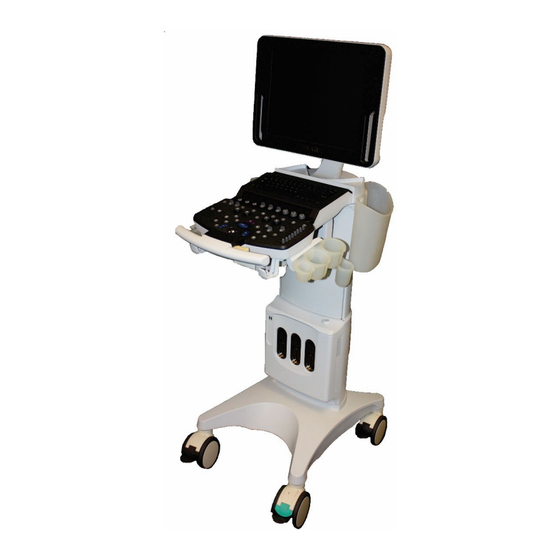
2. Getting Started Please read this document carefully before using the ultrasound system. Overview of Console, System and Features 17 inch display Speakers User Interface Storage Bins Gel Bottle Holder Control Panel height adjust Cable management hooks Power button 2 USB Ports Multi-Transducer Bins Port (MTP) - Page 14 Function Key which can be configured in Setup/Keys or alternately by using the Pointer to click on the Full Image Display ICON located in the lower left corner of the imaging screen. Once in Full Image Display, the screen will display Thumbnails or F Keys/OLEDs and Small Thumbnails.
- Page 15 Patient accession numbers, ID, name, age, DOB, gender, Operator ID etc. can be entered via a selection of Mindray-approved barcode readers that can connect to a system USB port (note: capability and content is dependent on type of scanner used).
- Page 16 Function Name Network port. Used for connecting router, ultrasound workstation, server, etc. Serial Port - eSATAp Used for connecting storage device. USB Port Used for connecting storage device. High definition Used for connecting TV, projector, multimedia interface. ultrasound workstation video capture card, etc.
- Page 17 Moving the z.one pro system Moving the System Lower the adjustable height to MINIMUM using the height adjustment release lever. Fold the monitor display down to a horizontal position and lock in place. The monitor arm will lock into a non-rotating position when the two parts of the articulating arm are in-line with each other AND centered with the system.
- Page 18 User Interface and Onscreen Display Figure 2.4: Keyboard Figure 2.5: User Interface (See Section 3 Imaging for more details) z.one pro Instructions 12 | P a g e...
- Page 19 User Interface (Special Procedures interface) z.one pro Instructions 13 | P a g e...
- Page 20 Patient and Institution Information Image Image Parameter Menu Area OLEDs Trackball – Priority ICON Programmable Keys z.one pro Instructions 14 | P a g e...
- Page 21 Figure 2.7: Full Image Onscreen Display Patient and Institution Information Includes Manufacturer Logo and Institution Name: Configured in Setup/System/General. Includes Patient Name, ID, Gender, and Age: Information entered on the Patient ID page. Also displays: Probe/Preset as selected with transducer, exam type, exam date/time, and Operator Menus Includes annotation lists, measurement options, calculations menus, stress echo navigation, and protocol information.
- Page 22 6 Priority States (Six squares with labels indicating states available to toggle. Active state • displayed in green font). Priority is changed as modes are turned on and off but can also be changed using the priority key on the user interface or by using the Pointer to point directly to the onscreen state desired. Softkey OLEDs Displays current functions of softkey OLED controls.
- Page 23 Quick Start Guide Figure 2.2: Control Panel Powering On/Off Press and release the Power button (located above the transducer connector) to turn the system on. Check the z.one pro display to ensure the startup screen is shown. When initialization is complete, the system is ready for imaging. To Power Off press and release the Power button.
- Page 24 Send Exams to USB Press Archive (back row of QWERTY keyboard). Point to the exam to send to USB. Select Send Exam from the drop down menu. This will launch a page to select the destination Select the Target Media from the list. Select file type (JPG/AVI, BMP/AVI, TIFF/AVI, DCM).
- Page 25 confirm. Click OK. To view the image in the image area, (Double Click) Set key. To return to live imaging, press Exit Review OLED Current Exam again. z.one pro Instructions 19 | P a g e...
-
Page 27: Imaging
3. Imaging Patient Information Press the New Patient key on the Alphanumeric Keyboard to enter Patient Information Select Transducer, Exam Type and Preset • General Information: • • Patient Name, ID, Gender, DOB, Age • Access Modality Worklist Diagnosis Information: •... - Page 28 Onscreen Help Bar will also include information to help the user navigate functions or features. (See User Interface / Onscreen Display for details. Control Description/Use Set Buttons Left and Right Set buttons provide primary functionality and navigation. For instance: Selecting calculations, •...
- Page 29 Priority Button Press the Priority button to gain access to OLED controls assigned to modes that are ‘ON’ but do not have priority. Onscreen Trackball - Priority ICON reflects changes. For example, while PW Doppler is active, the OLED controls and Onscreen Trackball - Priority ICON will reflect PW Mode controls as the active mode.
- Page 30 Overall/DGC gain: Press the Optimize button to automatically balance the Optimize overall/DGC gain. The B-Mode image adjusts the brightness of the image to the default target gain value. Sound speed compensation: Press and hold down Optimize to automatically compensate for the sound speed in tissue. The B-Mode image pauses momentarily, then adjusts for the detected sound speed.
- Page 31 HD Scope Description/Use Control HD Scope Toggle the OLED up to turn HD Scope on and off and down to turn pHD Scope on and off. pHD Scope Alternately, a programmable key can be assigned to turn these functions on and off. HDOff, HD0, HD1, HD2, Turn the OLED dial to toggle HD ‘Settings’, which are predefined multi-imaging parameter combinations for faster optimization.
- Page 32 Anatomic M-Mode can be configured to a Programmable Function key. These keys can be configured in Setup/Keys. Press Setup -> Keys. Select an ‘F’ key Click to select Anatomic M-Mode from the drop down menu. Click Save to complete the setting. ...
- Page 33 Rotate the outer ring of the M-Mode button to adjust the M-Mode strip gain. Gain Increasing the gain will brighten the M-Mode strip, increasing received signals. However, noise may also be increased. Priority Press the Priority button to gain access to OLED controls assigned to modes that are ‘ON’...
- Page 34 Frequency Press the Frequency button to cycle through the transmit frequency choices for CM Mode. The selected value is displayed in the Image Information area. lease select the frequency according to the detection depth and current tissue features. Priority Press the Priority button to gain access to OLED controls assigned to modes that are ‘ON’...
- Page 35 The optimization controls available in PDI, dPDI, and cTDI are generally the same as in CDV. Spectral Doppler Mode Controls (Pulsed Wave, Continuous Wave, and Tissue Doppler) Note: Continuous Wave Doppler imaging is available only on z.one pro systems equipped with the Echocardiology or Advanced Vascular Options.
- Page 36 on the onscreen Trackball Priority ICON with the Trackball and Set Keys. CINE Control Description/Use Trim Pressing this control allows user to trim a section of cine buffer or stored clips, to save as separate clips Cine Flush Pushing the dial flushes the CINE buffer resetting the frame counter to 0 Retro Toggle Retrospective Capture On and Off On/Off...
- Page 37 Pressing this knob toggles between controlling the position and size of the Resp trace. Turning the knob changes the position or size. NOTE: Mindray recommends the following ECG patient cables and lead wires from Advantage Medical Cables (AMC) (www.advantagemed.com): z.one pro Instructions z.one pro Instructions...
-
Page 39: Transducers And Needle-Guided Brackets
Always examine transducers for damage, such as cracks, splitting, holes, or fluid leaks. If damage is evident, discontinue use of the transducer and contact Mindray. Transducers NOTE (1): The z.one pro Ultrasound System is designed for compatibility with the following transducers. - Page 40 Transducer Applications for the Applications for the Applications for Pictures FDA Region Canada Region Other Regions A2CW Pediatric, Cardiac Pediatric, Cardiac Adult Cardiac, Adult, Cardiac Adult, Cardiac Pediatric Pediatric Cardiac, Pediatric Pediatric A5CW Pediatric, Peripheral Pediatric, Peripheral Pediatric, Peripheral vessel vessel Vascular C4-1...
- Page 41 Transducer Applications for the Applications for the Applications for Pictures FDA Region Canada Region Other Regions C6-1 Fetal, Abdominal Fetal, Abdominal Abdominal (includes (includes renal, (includes renal, renal, GYN/Pelvic), GYN/Pelvic), Pediatric, GYN/Pelvic), Pediatric, Contrast, Fetal, Peripheral vessel Peripheral vessel Pediatric, Peripheral Vascular, Urology C8-3 3D Fetal, Abdominal...
- Page 42 Transducer Applications for the Applications for the Applications for Pictures FDA Region Canada Region Other Regions C9-3sp Fetal, Abdominal Fetal, Abdominal Abdominal (includes (includes renal, (includes renal, renal, GYN/Pelvic), GYN/Pelvic), Intra GYN/Pelvic), Intra Contrast, Fetal, operative include operative include Intraoperative (abdominal, and (abdominal, and (Neuro, abdominal,...
- Page 43 Transducer Applications for the Applications for the Applications for Pictures FDA Region Canada Region Other Regions C18-5 Ophthalmic, Fetal, Ophthalmic, Fetal, Ophthalmic, Abdominal (includes Abdominal (includes Abdominal (includes renal, GYN/Pelvic), renal, GYN/Pelvic), renal, GYN/Pelvic), Intra-operative Pediatric, Small Organ Contrast, Fetal, (abdominal, thoracic (Thyroid, Breast, Musculo-skel...
- Page 44 Transducer Applications for the Applications for the Applications for Pictures FDA Region Canada Region Other Regions E9-3 Fetal, Abdominal Fetal, Abdominal Abdominal (includes (includes renal, (includes renal, renal, GYN/Pelvic), GYN/Pelvic), Trans- GYN/Pelvic), Trans- Fetal, Trans-rectal, rectal, Trans-vaginal rectal, Trans-vaginal Trans-vaginal, Contrast E9-4 Fetal, Abdominal...
- Page 45 Transducer Applications for the Applications for the Applications for Pictures FDA Region Canada Region Other Regions L8-3 Fetal, Abdominal Fetal, Abdominal Fetal, Abdominal (includes renal, (includes renal, (includes renal, GYN/Pelvic), Intra- GYN/Pelvic), Pediatric, GYN/Pelvic), Intra- operative (abdominal, Small Organ (Thyroid, operative (Neuro, thoracic (Cardiac) and Breast, Testes, etc.),...
- Page 46 Transducer Applications for the Applications for the Applications for Pictures FDA Region Canada Region Other Regions L14-5w Ophthalmic, Fetal, Ophthalmic, Fetal, Ophthalmic, Abdominal (includes Abdominal (includes Abdominal (includes renal, GYN/Pelvic), renal, GYN/Pelvic), renal, GYN/Pelvic), Intra-operative Pediatric, Small Organ Contrast, Fetal, (abdominal, thoracic (Thyroid, Breast, Intraoperative...
- Page 47 Transducer Applications for the Applications for the Applications for Pictures FDA Region Canada Region Other Regions L20-5 Ophthalmic, Fetal, Ophthalmic, Fetal, Ophthalmic, Abdominal (includes Abdominal (includes Abdominal (includes renal, GYN/Pelvic, renal, GYN/Pelvic, renal, GYN/Pelvic), Intra-operative Pediatric, Small Organ Contrast, Fetal, (abdominal, thoracic (Thyroid, Breast, Intraoperative...
- Page 48 Transducer Applications for the Applications for the Applications for Pictures FDA Region Canada Region Other Regions P8-3mTEE Trans-esoph. (non- Trans-esoph. (non- Transesophageal Card.), Trans-esoph. Card.), Trans-esoph. Echocardiography (Cardiac) (Cardiac) (non-cardiac and cardiac), Contrast P9-3ic Intra-cardiac L30-8 Ophthalmic, Small Ophthalmic, Small Organ (Thyroid, Parts, Vascular, Breast, Testes, etc.),...
- Page 49 Transducer Applications for the Applications for the Applications for Pictures FDA Region Canada Region Other Regions C12-4lp Laparoscopic Notes: For details about the P8-3TEE and P8-3mTEE transducers, please refer to the TEE transducer manual. For details about the C12-4lp transducer, please refer to the laparoscopic transducer manual. 41 | P a g e...
-
Page 50: Needle-Guided Bracket
Needle-guided brackets are available for purchase as optional accessories and are used in combination with the probe. Some probes have corresponding needle-guided brackets and needles. To order needle-guided brackets, contact the MINDRAY Customer Service Department or a sales representative. For biopsy or treatment, ultrasound-guided biopsy procedures can be performed using the probe together with a needle-guided bracket (optional accessory) and a biopsy needle (provided by the user). - Page 51 NGB-022 Metal/needle undetachable needle-guided bracket Needle fixing nut Groove Lock pin Clamp Needle type dial scale Angle adjusting base Angle fixing nut Needle guide hole Installing the Needle-Guided Bracket NGB-022 (1) Put on the sterile transducer sheath. (2) Hold the transducer by one hand, select the proper needle-guided bracket, and hold it with the other hand.
-
Page 52: Tee Transducers/Laparoscopic Transducers
(2) Separate the bracket and the transducer from the needle. (3) Screw the pinch nut to release the needle-guided bracket. (4) Separate the bracket and the transducer. Biopsy Menu/Guideline Verification Adjusting the needle mark is necessary before each biopsy procedure. 1. - Page 53 Refer to TEE and laparoscopic Transducer for instructions on inspecting, cleaning, and maintaining the TEE and laparoscopic transducers. C12-4lp Left Zero position Right Right Left Zero position Down Down Figure 4-1: Laparoscopic Transducer Handle and Adjusting Levers Scan plane rotation is controlled by two adjusting levers on the control handle and can be rotated from -90°...
- Page 54 Figure 4-2: Adult TEE Transducer Handle and Scan Plane Adjustments Figure 4-3: Adult TEE Transducer Tip Deflection Controls z.one pro Instructions 46 | P a g e...
- Page 55 Figure 4-4: Adult TEE Transducer Lock Operation P8-3m TEE The smaller wheel on the handle of the transducer controls the scan plane. The transducer scan plane can be rotated from 0° (transversal plane) to 90° (longitudinal plane) to 180° (transversal plane, left/right inverted) All planes in between can also be chosen.
- Page 56 Figure 4-6: P8-3m Adult and Pediatric TEE Scan Plane adjustment Lock Up/D Lock - Red Unlock Figure 4-7: P8-3m Adult and Pediatric TEE Lock Operation The TEE probes include sensors to monitor the temperature of the tip during use. While imaging the following on-screen indicator is shown: The angle of rotation shows the scan plane rotation while the temperature indicator shows the temperature at the transducer face.
- Page 57 off if the temperature is below 40.5ºC. Above that temperature the indicator will always be displayed. In addition: If the temperature reaches 41.5ºC the system will automatically freeze and display a • warning message. This warning message can be dismissed and imaging can continue.
-
Page 58: Wearing The Probe Sheath
Small Abdomina Cardia Transducer Obstetrics Gynecology Vascular Pediatric Urology Parts E9-3 3D E9-3 E9-4 P4-1c P8-3TEE P8-3m TEE P9-3ic L30-8 P7-3c C12-4lp Wearing the Probe Sheath A legally marketed probe sheath must be installed over the probe before performing intra- cavitary and intra-operative examination. - Page 59 1. Place an appropriate amount of gel 2. Insert the probe into the sheath; make inside the sheath or on the probe sure to use proper sterile technique. Pull acoustic lens. Poor imaging may cover tightly over probe acoustic lens to result if no gel is used.
- Page 60 Probe Length(mm) Width(mm) Height(mm) Cable Length(mm) C18-5 24.1 1980±50 L14-5w 66.5 25.6 1980±50 L14-5sp 95.1 70.8 25.4 2489±50 L10-5 106.5 43.3 1950±50 L20-5 24.1 1980±50 L8-3 100.1 56.3 27.9 1950±50 E9-3 3D 297.1 39.6 32.2 1950±50 E9-3 44.6 34.2 1950±50 E9-4 44.6 34.2...
-
Page 61: Transducer Tracking
Transducer Tracking Transducer Tracking is a feature designed to track usage of transducers by serial number. Press the Service key on the Alphanumeric Keyboard To Enable Transducer Tracking • Check the desired Data Retention box to establish timeframe to maintain this data •... - Page 62 Press the key and select the buttons to include the Setup DICOM Set DICOM Service • Transducer Information in the DICOM transfer. z.one pro Instructions 54 | P a g e...
-
Page 63: Measurements And Calculations
5. Measurements and Calculations Basic Measurements Operation Measurements and calculations can be performed on zoomed images, stored images, real- time images or frozen images. Control Description/Use Caliper Button Generic measurement tool are accessed in all imaging modes by pressing the Caliper button. A subset of measurements is available in live imaging. - Page 64 The system displays and updates measurement and calculations results in the Results Window. Point to and press Set to move the Results Window around the imaging area as needed. Help information concerning measurement and calculations is displayed in the Help Bar at the bottom of the screen.
- Page 65 Distance (A/B) Measures the lengths of any two lines and calculates the ratio. Ratio Area Ratio Measures the areas of any two regions and calculates the ratio. Measurement Tools Available Function using the Caliper Button Volume Measures the volume of cardiac chambers (Bullet, Simpson) M-Mode The following M Mode measurement tools are available by pressing the Caliper key.
- Page 66 Velocity of two peaks on the Doppler spectrum are measured to calculate the ratio A/B. N intervals (n≤8) are measured to calculate a PW mode derived HR value in Beats Per Minute (BPM). Measuremen Function Measures the Peak Systolic Velocity of a waveform; the highest velocity of red blood cells crossing the sample volume.
- Page 67 OB - used for measuring fetal growth indices (including EFW) as well as GA and EDD calculations. The fetus can be evaluated through growth graph analysis and the fetal biophysical profile. Cardiac - used for left ventricle function measurements and measuring chambers, main artery and vein parameters, etc.
- Page 68 Configuration Auto IMT is a purchased license. Please confirm Auto IMT has been configured before use. Operations are as follows: Press <Service> key to enter User Diagnostics Panel interface. Click [License Info] to enter License Information interface, and check if Auto IMT is displayed on Features list.
- Page 69 Acquire an apical two-chamber view to measure the EDV(A2C) and ESV(A2C) and/or Acquire an apical four-chamber view to measure the EDV (A4C) and ESV (A4C). Press Freeze. Press <Calc> key to enter measurement mode and select Auto EF or press the programmable key assigned to Auto EF.
- Page 70 Table 3 1D image measurements Parameter Range Error Distance Full Screen Within ±3% Time Timeline Display Within ±2% Heart Rate Timeline Display Within ±4% 10-200cm/s (for C4-1, C10- 3, C6-2, C9-3, C8-3 3D, E9-3, E9-4, E9-3 3D, L10- 5, L8-3, L14-5sp, L14-5w, When angle ≤60º, ≤5%.
-
Page 71: Annotations, Arrows, And Body Markers
6. Annotations, Arrows, and Body Markers Annotations Enter Annotation Text Manually The annotation function may be invoked by pressing the Spacebar, the Text key on the keyboard, or the Annotation button on the console. The trackball is used to define where onscreen the text will be written. - Page 72 Text can be temporarily removed from the screen by pressing the softkey OLED • Display Text and can be replaced onscreen by pressing Display Text again. Moving Text: A block of text can be moved around the screen by double-clicking the •...
- Page 73 Moving transducer designator on Body Marker: When Body Marker is activated, the transducer is attached to the trackball, so • moving the trackball will move the location of the transducer designator within the Body Marker. Rotate the transducer by: • •...
-
Page 75: Archiving, Review And Management
7. Archiving, Review and Management Image Print and Storage There are three keys that can be configured to either print or store: Store 1, Store 2, Print. These can be configured to send still images, clips, and screen shots to an optional printer, hard drive, USB device, DICOM networked device, or FTP site. - Page 76 active exam. Archive: Press Keyboard control to display a list of previous exams. By default this • shows the list of exams present on the internal hard drive. • A drop-down menu on this screen (Data Source) will switch to a list from media inserted in the USB port.
- Page 77 Figure 7-2: Setup; General; Auto Launch Total Recall Imaging Selectively Load Total Recall Data: No Setup is necessary. • • Total Recall data will NOT automatically be loaded when an image or clip is selected for Review • An OLED will become available with options to ‘Load TRI’ or ‘Delete TRI’ data if an image with TRI data is selected for Review.
- Page 78 If Total Recall Data is automatically loaded, turn the dial to toggle between Exit • TRI and Delete TRI, then press the dial to select the action. Load/Delete/Exit If Total Recall Data is not automatically loaded, turn the dial and then press the •...
- Page 79 external media. Data can be restored to the ultrasound system if this method of copying is selected. Exams that are backed up to external media can be restored to the Restore Exam: • ultrasound system using this option. Select the exam from the list of exams on the external media.
- Page 80 Images can be imported from a USB device and added to existing collections using the • Import to Image Gallery onscreen button. From the Archive Page • Check Image Gallery box to display and sort Image Gallery collections only for easy •...
- Page 81 Wireless (Option) Mindray supports wireless connectivity using the Quatech Airborne Direct Wireless Ethernet Bridge. This is intended as a workflow enhancement to enable remote viewing and archival of data when a physical Ethernet connection is not available. It should not be relied upon however when time-critical diagnoses are required as multiple environmental factors may affect wireless connectivity performance.
-
Page 83: Advanced Features And Options
8. Advanced Features and Options Contrast Enhanced Ultrasound (CEUS) Contrast imaging is a separately purchased option. It is a detection mode specifically designed to enhance ultrasound contrast agent signals. Similar to 2D (B-Mode), a suite of additional optimization controls are provided to further enhance contrast agent imaging performance. The contrast imaging is used in conjunction with ultrasound contrast agents to enhance imaging of blood flow and microcirculation. - Page 84 2. Click to select CEUS to the desired key. 3. Click Save to complete the setting. Once configured, CEUS is invoked by pressing the configured function key. General Imaging - By default the image presents as a dual display, with the contrast image on the left and a reference image on the right (OLED control available to have contrast image on right and reference image on the left).
- Page 85 While in Contrast (CEUS), the softkey OLEDs display options specific to contrast imaging. Contrast Control Description/Use Softkeys OLED While CEUS is active, the Softkeys at the back of the console contain the controls o p t i m i z a t i o n and navigation controls specific to CEUS Imaging and affecting the CEUS image only.
-
Page 86: Elastography
Play/Pause When the image is frozen, this control provides a means to toggle between playing and pausing the contents of the Cine Buffer. When Paused, the same dial navigates frame by frame. When the image is playing, this control increases and/or decreases the playback speed. - Page 87 Strain Elastography Strain Elastography is a separately purchased option. Elastography must be configured to a programmable function before use. These keys can be configured in Setup/Keys. Once configured, elastography is invoked by pressing the configured function key. By default the image goes to a dual display, with the elastography image on the left and a reference image on the right.
- Page 88 The image will pause momentarily while the ARFI is fired and then return to live imaging. A results box will appear on the screen with the ARFI data, ROI size, ROI position, and Quality Factor in one of three forms as shown below: a) If a site or segment was not selected before pressing Select to start ARFI, generic data...
- Page 89 ARFI Control Description/Use Liver Segment Indicates which liver segment is being measured (values: 1, 2, 3, 4a, 4b, 5, 6, 7, 8) Push the dial to turn the onscreen graphic on and off. Turn the dial to change the segment and onscreen graphic display which will automatically label ARFI acquisitions by segment to be stored in the report If this control is off, users can assign ARFI measurement to a generic site or liver segment after it has been acquired as described in calculations section.
- Page 90 Press the <Select> key to start an ARFI acquisition. The ARFI Velocity result window will display on the image area. The stiffness is converted into a velocity value by the formula: stiffness √ , ρ = 1.03. ARFI velocity 3*ρ The measurement accuracy of the ARFI velocity is about 50%, and the measure repeatability of the ARFI velocity is about 20% ...
-
Page 91: D & 4D Imaging With Advanced Lighting (Option)
9. 3D & 4D Imaging with Advanced Lighting (Option) 3D/4D imaging is available on z.one pro when used with the C8-3 3D or E9-3 3D transducers. A Programmable Function key must be assigned to 3D in order to invoke 3D/4D imaging. These keys can be configured in Setup / Keys / Programmable Keys. - Page 92 One-up / 4-up Toggle Press to display Volume as a single, large image Softkey Label: Press again to return to 4-up (A, B, C planes and Volume) Acquisition Quality Press to select the Quality factor of the Volume set: Softkey Label: Quality HIGH / BALanced / FAST Default is HIGH Elevation Sweep Angle...
- Page 93 Light (6 Directions) Toggle up or down to select the light direction for the active volume. Softkey Label: Default is front view. Trackball will also control direction of light while this softkey is active. Volume Rotation Press to rotate the volume to one of 4 discrete degrees: Softkey Label: 0 / 90 / 180 / 270 Default is 270 degrees.
- Page 94 Render Quality Changes the resolution quality of the rendered image Press arrows to make selection: FAST / BALANCED / HIGH / MAX Chosen option displays on Data Display Tint Press arrows to select among 4 tints: 1 gray / 3 colorized Render Smoothing Press arrows to select the amount of smoothing desired: 0 / 1 / 2 / 3 / 4 / 5...
- Page 95 an onscreen graphic is displayed with direction of the light. The Light softkey controls the direction of the light. Figure 9-2: Render Mode with Light Figure 9-3: Light Direction Examples MPR Mode MPR mode displays orthogonal planes (A, B & C) vertically; larger image is blow up of active image Figure 9-4: MPR Mode Features include:...
- Page 96 Tomo Mode In Tomo mode, 9 images are displayed (9-up) with one image as reference for slices. Figure 9-5: Tomo Mode Features include the following abilities: Change line spacing between slices in mm and position of the set of lines using the •...
-
Page 97: Needle Optimization Mode (For Improved Needle Visualization)
10. Needle Optimization Mode (For Improved Needle Visualization) Needle Opt Mode provides for improved needle visualization by adjusting system parameters to optimally receive echoes from needles. Needle Opt Mode is available on the z.one pro when using the L14-5w, L20-5, L10-5 and L8-3 transducers during B-Mode Imaging. - Page 98 Figure 10-1 Optimum Needle Opt Setup Needle and dotted line of the shaded area form a 90 degree angle z.one pro Instructions 88 | P a g e...
-
Page 99: Protocols
11. Protocols Protocols Overview The main objective of ultrasound workflow automation (Protocols) is to speed up exam times and reduce the excessive number of user interface manual key strokes that can lead to repetitive strain injuries over time. Protocols automate clinical workflow in a logical “step by step” manner. They also prevent missing important parts of examinations as well as decreasing exam times. - Page 100 The following Softkey (OLED) controls are available while Protocol is active. Soft Keys (OLED) Protocol Control Description/Use General Softkeys OLED Repeat views, replace views, overwrite multiple views in sequence, delete views, and controls advance or go back views. Suspend Protocol Press the Softkey OLED to Suspend protocols to evaluate anatomy and pathology...
-
Page 101: Stress Echo
12. Stress Echo Stress Echo Overview CAUTION: Stress echo data are provided for reference only, not for confirming diagnoses. Overview Stress Echo is an option. The Stress Echo feature allows you to capture and review cardiac clips for multiple-phase (multiple-stage) Stress Echo protocols. Stress Echo data consists of Stress Echo loops, wall motion scores, and all other information pertaining to the Stress Echo portion of a patient examination. - Page 102 Programmable Key Pressed Protocol Key Pressed Onscreen prompts in the Help Bar will guide the user in terms of next keys to press to advance the Stress Echo protocol. Where not labeled, pointing to onscreen controls will display a quick hint as to function of the control.
- Page 103 the continuous capture. To halt saving acquired images for the selected stage, press <Freeze> directly. The time stops increasing. Press <Freeze> again to continue. To end the current acquisition, press <Store> on the control panel. To select another continuous stage, press <Stage XXX> key. ...
- Page 104 Select Mode Stage and available End SE Mode views to choose from Suspend SE. If SE is Suspend exam: If SE Stages Navigation arrows for suspended, pressing is suspended, available images and Protocol key or pressing Views pages programmable key programmable key assigned to SE will re- assigned to SE will...
-
Page 105: Setup
13. Setup The Setup function is designed to set the configuration parameters of operating the system and maintaining user workflow setup data. The setup data of the user and system are stored to the hard drive, and should be backed up to USB memory device. To enter Setup, press the Setup key on the User Interface. - Page 106 Preset Description of Control Management Enable / Disable Select transducer, category and preset combinations that will be available for selection. Exam Type can be disabled independent or transducer/preset. Customization Assign Exam Type and Preset to softkey OLED controls for easy access Delete Select User Presets for deletion by transducer and category.
- Page 107 Stress Echo Description of Control Protocol Create, edit, import, load, and delete SE protocols Maintenance Select and configure onscreen labels, ROI type, and default WMS type. Customize or reset clip triggers. DICOM – Set Description of Control DICOM Service Storage Configure a DICOM destination including AE Title, port, transfer specifics and options, and image/clip specifics and options including Tissue Tracking.
- Page 108 Keys Description of Control Programmable Configure exam category (Cardiac, Abdominal, Obstetrics, Gynecology, Vascular, Keys Pediatrics, Urology, POC, and Small Parts) specific programmable keys including Function keys, and Footswitches. Selections are also available to configure the B Mode Knob (B Mode or B Mode Home) and trackball speed which are not category specific.
-
Page 109: System Security
14. System Security System security features available on the z.one pro platform include Anti-Virus Scan, Secure Data Deletion, Patient Data Encryption, Password Protected User Accounts, Secure Network Transfers, and Backup to external media with Encryption. Anti-Virus The Anti-Virus scan feature is accessed under the boot_app display (press Service Key/ select Maintenance / select Service Reboot softkey to access the boot_app display). - Page 110 Patient exam data can be encrypted and then stored to the system hard drive in conformance with the Advanced Encryption Standard (AES). (***Note: The archive must be empty to either enable or disable encryption.) Configuration options are available through Setup; System; Security/ Exam Data Encryption A password is required to enable and disable encryption.
- Page 111 for any user login; whereas, other users can only change their own login passwords. Admin • Operator • Emergency • Passwords must include the following to be considered ‘strong’: 6-16 alpha-numeric characters • At least two uppercase letters • At least two lowercase letters •...
- Page 112 Lightweight Directory Access Protocol (LDAP) Configuration z.one pro integrates with existing Lightweight Directory Access Protocol server on the customer premise for centralized user authentication. To configure, press the Setup key; select the Security Tab; Enable User Account Control; LDAP Configuration and follow onscreen prompts. Secure Network Transfers Patient data can be transferred over a network VPN connection using TLS/SSL encryption (TLS 1, 2 or above).
- Page 113 Backup Exam Data to USB with Encryption The z.one pro system can be set up to encrypt patient exam data before backing up the data to removable media like USB. Select a patient exam from the Archive. Choose Backup Exam and select the appropriate external media as the destination.
-
Page 115: Maintenance
Capturing current image screen and storing as a BMP file • Transferring the contents of the internal log directory (using an internet connection) to • the MINDRAY/ZONARE FTP site Checking (over the Internet) for availability of software and firmware (cart) updates from • the MINDRAY/ZONARE FTP site Transducer diagnostics •... - Page 116 Press the Undo key to exit transducer diagnostics. Notes: Probe check is provided for reference only, not for confirming a diagnosis. Each time a transducer is connected to the main system or activated, the users are recommended to implement probe check of transducer performance. System Care and Cleaning Before cleaning, turn off the AC circuit breaker on the z.one pro system to remove all power from the unit.
-
Page 117: Safety
Permanently installed or non-permanently installed: Non-permanently installed Safety Standards All MINDRAY/ZONARE instruments, cables, and diagnostic ultrasound imaging transducers have been designed to meet the essential requirements contained in 93/42/EEC (Medical Device Directive), and all appropriate requirements contained within IEC 60601-1, AAMI STD ES 60601-1, CSA STD C22.2 NO. 60601-1 (Medical electrical... - Page 118 Ultrasound System and compatible transducers. Warnings Do not use an aftermarket probe other than those specified by Mindray. The probes may • damage the system causing a profound failure, e.g. a fire in the worst case.
- Page 119 The system does not contain a user-serviceable lithium ion battery. • The optional ZPAK cart battery is not a user serviceable item. Contact Mindray Technical • Support group for assistance with the ZPAK battery. Follow guidelines provided by relevant IEC standards when connecting peripherals.
- Page 120 If using relevant IEC standards compliant equipment that was not provided by • MINDRAY/ZONARE, it is required that total leakage currents be tested and validated to be below the IEC 60601-1 limits in chapter 21. This equipment must only be connected to a supply main with protective earth.
- Page 121 Use only the recommended patient cable supplied by Mindray. Make sure that bare parts of the electrodes and the patient do not come in contact with conductive parts, such as metal examination beds, trolleys, and similar items.
- Page 122 The systems and/or the external equipment can be damaged if signal levels are not appropriate. If peripheral equipment not specifically authorized by Mindray is to be connected to the system, it must meet all applicable electrical safety standards that apply to the system in order to maintain safety integrity.
- Page 123 (including the warranties of merchantability or fitness for a particular use), with respect to such devices. Use of peripherals or other equipment not provided by Mindray may result in system damage or •...
- Page 124 previous patient exam directory. Some components or devices such as transducer covers used with systems are for single- • patient use only. Reuse, reprocessing, or re-sterilization of these devices may compromise their structural integrity. Any image sets stored on the system that are not identified by patient name and number will •...
- Page 125 TEE Quick Reference Guide for details. TEE: Clean and disinfect after each use. • TEE: Always use a bite guard. • TEE: Always use single-use probe sheath. • TEE: Ensure articulation locks are disengaged and straighten mechanism during device • insertion or extraction from patient.
- Page 126 A good B Mode/2D image is important for a high-quality 3D/4D image. • Precautions - WIRELESS WIRELESS: The Mindray Wireless option device is an RF Receiver and Transmitter, • operating using industry standard 802.11 b/g protocols. Use of the wireless option, in the presence of other high energy RF radiating devices may interfere with the transmission of data to the network interfaces.
- Page 127 understand the implications of such use. The American Institute of Ultrasound in Medicine (AIUM) has published a document titled Medical Ultrasound Safety (AIUM 1994). ALARA is an abbreviation for the principle of prudent use of diagnostic ultrasound by obtaining the diagnostic information at a power output that is as low as reasonably achievable.
-
Page 129: Acoustic Output
17. Acoustic Output This section describes acoustic-output-related parameters and considers the relation between these parameters and user controls on the systems. The display accuracy and measurements precision of these parameters is also discussed. Detailed information on acoustical power output for each transducer, in each operating modality, is in the dedicated table provided in Acoustic Power Manual. - Page 130 brochure developed by the American Institute of Ultrasound in Medicine (AIUM) and supplied with ultrasound systems. Direct Controls Per Track 3, the ultrasound system control acoustic output to not exceed a mechanical index (MI) level of 1.9, and I of 720 mW/cm or a thermal index (TI) value of 6.0.
- Page 131 Medical Diagnostic and Monitoring Equipment and the United States Food and Drug Administration’s Guidance Document, “Information for Manufacturers Seeking Marketing Clearance of Diagnostic Ultrasound Systems and Transducers” limits.. Transmit Power: Transmit power controls the transmit voltage, and therefore the amplitude of the transmitted ultrasonic waves.
- Page 132 decrease the TI, and an increasing frame rate may increase the TI. Color Doppler Controls Image Width: Narrowing the image width may increase the frame rate, which may increase the TI. Velocity Scale: Increasing the Velocity scale may increase the TI by increasing the pulse repetition frequency.
- Page 133 Combinational with B, COLOR and PW: Use of combination modes affects the TI and MI through the combination of pulse types. Because the TI is additive, simultaneous pulsing of B, COLOR and PW modes may cause larger TI values than sequential pulsing (e.g. auto- update).
-
Page 135: Display Accuracy And Precision
18. Display Accuracy and Precision The output display indices are calculated with the accuracy described below. Also listed is the precision of the displays. A discussion of the accuracy statements follows their specification. Thermal Index Display Accuracy and Precision It is estimated that 90% of TI values will be +/– 45% of the displayed TI value or +/–... - Page 136 percentage. Measurement Uncertainty Parameter Description Uncertainty Pulse Intensity Integral (PII) ) in an ultrasonic pressure wave. +20.4% Energy density (mJoules/cm Used in TI, Ispta.0, and Ispta.3 determination. -26.5% Peak Rarefactional Pressure (Pr) Largest pressure amplitude (MPa) of the negative pressure. +11.7% Used in MI determination.
-
Page 137: Guidance Documents
19. Guidance Documents Medical Ultrasound Safety. American Institute of Ultrasound in Medical (AIUM), 1994. NEMA UD 2, Acoustic Output Measurement Standard for Diagnostic Ultrasound Equipment, Revision 3. National Electrical Manufacturers Association, American Institute of Ultrasound in Medicine, 2004. Acoustic Output Measurement and Labeling Standard for Diagnostic Ultrasound Equipment. American Institute of Ultrasound in Medical (AIUM), January 1998. -
Page 139: Standards And Compliance
20. Standards and Compliance z.one pro system has been designed, manufactured, tested, and certified to comply with the following internationally recognized standards: IEC 60601-1: 2012: Medical electrical equipment part 1: General requirements for basic safety and essential performance. IEC 60601-1-2: 2014: Medical electrical equipment part 1-2: General requirements for basic safety and essential performance. - Page 140 The system complies with the EMC standard IEC 60601-1-2: 2014. Intended Environments: Professional healthcare facility environment. WARNING: The use of unapproved accessories may diminish system performance. Use of components, accessories, probes, and cables other than those specified may result in increased emission or decreased immunity of system.
- Page 141 Imaging; Doppler acoustic spectral displaying; Taking measurements; Patient information; Date/time information. TABLE 1 GUIDANCE AND MINDRAY DECLARATION—ELECTROMAGNETIC The system is intended for use in the electromagnetic environment specified below. ELECTROMAGNETIC ENVIROMENT- EMISSIONS TEST COMPLIANCE GUIDANCE RF emissions The system uses RF energy only for its...
- Page 142 TABLE 2 GUIDANCE AND MINDRAY DECLARATION—ELECTROMAGNETIC The system is intended for use in the electromagnetic environment specified below. COMPLIAN ELECTROMAGNETI IMMUNITY TEST 60601 C ENVIRONMENT- Electrostatic Floors should be wood, Discharge(ES concrete or ceramic tile. If D) IEC floors are covered with ±8 kV contact;...
- Page 143 TABLE 3 GUIDANCE AND MINDRAY DECLARATION—ELECTROMAGNETIC The system is intended for use in the electromagnetic environment specified below. The customer IEC 60601 COMPLIAN ELECTROMAGNETIC IMMUNITY TEST ENVIRONMENT- TEST LEVEL LEVEL GUIDANCE 3 Vrms 3 Vrms Conduced RF Portable and mobile RF 0,15 MHz –...
- Page 144 TABLE 4 RECOMMENDED SEPARATION DISTANCES BETWEEN PORTABLE AND MOBILE The system is intended for use in an electromagnetic environment in which radiated disturbance are controlled. The customer or the user of system can help prevent electromagnetic interference by maintaining a minimum distance between portable and mobile RF communication equipment (transmitters) and system as d d b l t th...
-
Page 145: Product Labeling
21. Product Labeling Contact Mindray if any of the labels are missing or damaged beyond legibility. With the ultrasound system, the L10-5 and L14-5sp transducers are classified as Type-CF (Cardiac Floating). All other transducer types are Type-BF (Body Floating). Earlier transducers labeled without these symbols are Type-BF. -
Page 147: Specifications
22. Specifications Parameter Value Type Electrical Power requirements 100–240V~, 50–60Hz, 6A max Battery Battery power supply voltage DC 15.6V (NiMH battery) Battery capacity No less than 13000mAh for a single battery (NiMH battery) The main unit working time when powered by At least 1.5 hours (NiMH battery) battery Battery charging time... - Page 148 Type Parameter Value Wireless Option Manufacturer PN: ABDN-ER-DP551U Wireless Technology IEEE 802.11a/b/g/n, Wi-Fi compliant Wired Interface 10/100 Ethernet port (Bridge, Router (NAT3) Modes) Frequency DSSS, CCK, OFDM Modulation Technology DSSS, CCK, OFDM Modulation Type DBPSK, DQPSK, CCK, BPSK, QPSK, 16QAM, 64QAM Network Access Modes Infrastructure, Ad Hoc Channels...
- Page 149 Type Parameter Value Wireless Option Wireless Security Disabled, WEP 64 & 128bit, WPA (TKIP), WPA (AES), WPA2 (AES), 802.1x (EAP) Supplicant 802.11I, WPA & WPA2 Enterprise supplicants (EAP-TLS, EAP-TTLS (MSCHAPv2), EAPTTLS (MDS5), EAP- PEAPv0 (MSCHAPv2, LEAP), EAP- FAST, LEAP) Supports Certificates and Private Key Upload and Storage (Multiple) Antenna...
- Page 150 Database Sqlite Database Version/Kernel Version: 3.6.16 Supplier: Open Source Operating Environment: Linux Cyber Security ClamAV Version/Kernel Version: 0.97 Supplier: Open Source Operating Environment: Linux Application Software OpenConnect Version/Kernel Version: 3.2 Supplier: Open Source Operating Environment: Linux Supplier: Open Source z.one pro Instructions 135 | P a g e...
- Page 151 P/N: 046-012366-01 (5.0)
Need help?
Do you have a question about the ZONARE z.one pro and is the answer not in the manual?
Questions and answers