
Related Manuals for Mindray DC-70 Pro


Summary of Contents for Mindray DC-70 Pro
- Page 1 DC-70/DC-70T/DC-70 Pro/DC-70 Exp/DC-70S/DC-75/DC-78/DC-75 Exp/DC-78 Exp/DC-70W/DC-70 CV/DC-70 Nova/DC-70 Plus/DC-68 Diagnostic Ultrasound System Service Manual Revision 7.0...
-
Page 3: Table Of Contents
Table of Content Table of Content ........................i Revision History ........................I Intellectual Property Statement ....................II Applicable for .........................II Statement ..........................II Responsibility on the Manufacturer Party .................III Customer Service Department ....................III Safety Precautions ..................... 1-1 Meaning of Signal Words ..................... 1-1 Symbols ..........................1-1 1.2.1 Meaning of Safety Symbols .................. - Page 4 3.4.2 Installing a Graph / Laser Printer ................3-10 3.4.3 Installing Video Printer ....................3-12 3.4.4 Position a Printer ......................3-12 3.4.5 Installing Barcode Scanner ..................3-13 System Configuration ......................3-14 3.5.1 Running the System ....................3-14 3.5.2 Enter Doppler ......................3-14 3.5.3 System Preset ......................
- Page 5 Function and Performance Checking Method ............5-1 NOTE ........................... 5-1 System Running Status ......................5-1 5.2.1 Running Status ......................5-1 5.2.2 Working Condition ......................5-1 General exam ........................5-2 5.3.1 Check Flow ........................5-2 5.3.2 Checking Content ......................5-2 Function Checking ......................... 5-5 5.4.1 Checking Flow ......................
- Page 6 Preparation ........................... 9-2 9.2.1 Disassembly Tools Required ..................9-2 9.2.2 Engineers Required ...................... 9-2 9.2.3 Disassembly Requirements ..................9-2 Assembly/Disassembly ......................9-2 9.3.1 Display (Monitor) Assembly ..................9-4 9.3.2 Probe Board Assembly ....................9-5 9.3.3 Disassembling ECG Assembly ..................9-6 9.3.4 Outlet Fan ........................
- Page 7 11.3.2 Abnormal Voltage of System Power ................11-8 11.3.3 Abnormal Temperature ....................11-9 11.3.4 Fan Error ........................11-10 11.3.5 PHV Error ........................11-11 11.3.6 Gel Warmer Abnormality ................... 11-12 11.3.7 Other Errors ......................11-13 11.4 Self Test ..........................11-13 11.4.1 Self Test Introduction ....................11-13 11.4.2 Operation Procedure of Maintenance Self Test ............
- Page 8 13.7.1 Related Modules or Boards ..................13-9 13.7.2 Key Points Supporting Troubleshooting ..............13-9 13.7.3 Troubleshooting of the Monitor ................... 13-9 13.8 ECG Module Failure ......................13-10 13.8.1 Related Modules or Boards ..................13-10 13.8.2 Key Points Supporting Troubleshooting ..............13-10 13.8.3 Troubleshooting for ECG Module ................
-
Page 9: Revision History
Revision History Mindray may revise this publication from time to time without written notice. Revision Date Reason for Change Initial release 2021.1 2021.04 Upgrade the FRU table Upgrade the FRU table 2021.10 2021.11 Upgrade the FRU table 2022.3 Upgrade TR64 board information in FRU table 1. -
Page 10: Intellectual Property Statement
Intellectual Property Statement SHENZHEN MINDRAY BIO-MEDICAL ELECTRONICS CO., LTD. (hereinafter called Mindray) owns the intellectual property rights to this Mindray product and this manual. This manual may referring to information protected by copyright or patents and does not convey any license under the patent rights or copyright of Mindray, or of others. -
Page 11: Customer Service Department
Mindray or repairs by people other than Mindray authorized personnel. -
Page 13: Safety Precautions
Safety Precautions This chapter describes important issues related to safety precautions, as well as the labels and icons on the ultrasound machine. Meaning of Signal Words DANGER WARNING CAUTION In this operator’s manual, the signal words NOTE and Tip are used regarding safety and other important instructions. The signal words and their meanings are defined as follows. -
Page 14: Warning Labels
1.2.2 Warning Labels Warning Labels Meaning a. Do not place the system on a sloped surface. Otherwise the system may slide, resulting in personal injury or the system malfunction. Two persons are required to move the system over a sloped surface. b. - Page 15 Symbol Description USB port Used for VGA output. Reserved, used for separate video output S-VIDEO Used for stereo audio output. AUDIO HDMI High definition multimedia interface. Microphone input jack When the lever located at the bottom of the monitor supporting arm points to you can move the monitor to the right and left.
-
Page 16: Safety Precautions
Use the power cord accompanied with the system provided by Mindray. Disconnect the AC power before you clean or uninstall the ultrasound machine, otherwise, electric shock may result. -
Page 17: Mechanical Safety
The user is not allowed to open the covers and panel of the system, neither NOTE: device disassemble is allowed. To ensure the system performance and safety, only Mindray engineers or engineers authorized by Mindray can perform maintenance. Only technical professionals from Mindray or engineers authorized by Mindray after training can perform maintenance. -
Page 19: Specifications
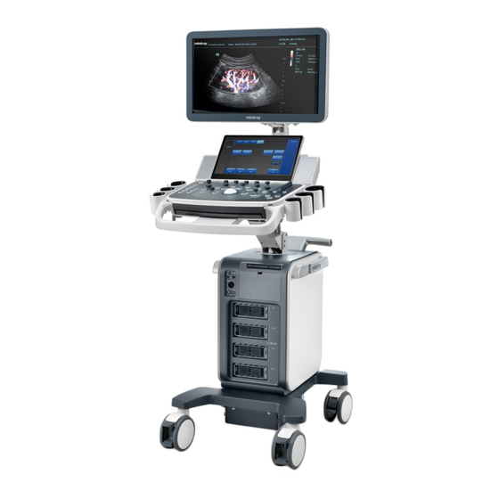
Specifications Overview 2.1.1 Intended Use The DC-70 series diagnostic ultrasound system is intended for use in clinical ultrasonic diagnosis. 2.1.2 Introduction of Each Unit Name Function Monitor Displays the images and parameters during scanning. Touch screen panel Operator-system interface or control. Speaker Sound output. - Page 20 Name Function Control panel adjusting Used for lifting or swiveling the control panel. lever Keyboard Used for typing characters or entering some functions. Main control panel Operator-system interface or control. USB_MIC port USB/MIC port Hanger Intracavitary probe Used for fixing the intracavitary probe. holder Ultrasound gel Used for placing the ultrasound gel or installing the gel warmer.
- Page 21 2.1.2.1 I/O panel Symbol Function <1> USB ports. <2> HDMI High definition multimedia interface. <3> Network port. <4> VGA signal output. <5> S-Video Used for separate video output. <6> Audio signal output port, left channel. Audio signal output port, right channel. <7>...
- Page 22 2.1.2.2 Power Supply Panel Name Function <1> Power outlet Supplies power to optional peripheral devices. <2> Power inlet AC power inlet. Equipotential terminal Used for equipotential bonding which balances the protective earth <3> potentials between the system and other electrical equipment. 2-4 Specifications...
- Page 23 2.1.2.3 Physio Panel Name Function <1> USB port Connects USB device. <2> Pencil probe port Used for connecting a pencil probe. <3> MIC port Used for connecting a microphone. Connects to ECG leads to directly obtain the patient's ECG ECG lead signal input signals.
- Page 24 2.1.2.4 Control Panel Name Description Power button <1> Press the button to turn on the system, the system enters the work status and the indicator becomes green. <2> Volume Adjust the volume. <3> <4> <5> Adjust the corresponding functions on the touch screen. <6>...
- Page 25 Name Description <13> End Exam End the current exam. <14> Text Enter/exit the textual comment status. <15> Clear Clear the comments or measurement caliper. Press to enter the Cine Review status from non-cine status when <16> Cine there is a multi-frame cine file playing. <17>...
- Page 26 Name Description <39> Move the trackball to change the cursor position. Confirm an operation. The function is same with the left-button of <40> the mouse. <41> Freeze Freeze/defreeze the image. <42> Save Save the image; user-defined key. <43> User-defined keys, functions of which can be defined in preset. <44>...
- Page 27 Keyboard Common functional keys Function Confirm the entered data, or move the cursor to the top of the next row of the Enter text or input field. Cancel the operation or exit. Jump to the next operable item. Space key Insert a space.
-
Page 28: Peripherals Supported
2.1.3 Peripherals Supported Item Model Black/white digital video MITSUBISHI P95DW-N, SONY UP-D898MD printer Black/white analog SONY UP-X898MD, MITSUBISHI P93W-Z video printer Color digital video SONY UP-D25MD printer HP Officejet 7000 wide format, HP Officejet Pro 8100 (the printer driver Graph/text printer requires manually installed) USB port: FS-81-SP-2 (1-pedal) Foot switch... -
Page 29: Monitor Specification
Do not use this system in the conditions other than those Warning: specified 2.2.4 Monitor Specification 2.2.4.1 Main Monitor Dimension 21.5 inch, 23.8 inch Resolution 1920×1080 Visible angle 89° left/right; 89° up/down 2.2.4.2 Touch Screen Dimension 13.3 inch Resolution 1920×1080 Visible angle 85°... -
Page 31: System Installation
System Installation Preparations for Installation Do not install the machine in the following locations: NOTE: Locations near heat generators; Locations of high humidity; Locations with flammable gases. 3.1.1 Electrical Requirements 3.1.1.1 Requirement of Regulated Power Supply Power specification is showing in chapter 2.2.2. Due to the difference of the power supply stability of different districts, please advise the user to adopt a regulator of good quality and performance such as an on-line UPS. -
Page 32: Installation Conditions
Installation Conditions 3.1.2 3.1.2.1 Space Requirements Place the system with necessary peripherals in a position that is convenient for operation: 1. Place the system in a room with good ventilation or an air conditioner. 2. The door is at least 0.8m wide. The ultrasound machines can move into the room easily. 3. -
Page 33: Confirmation Before Installation
3.1.3 Confirmation before Installation Perform the following confirmation before installing the system: 1. The video format used in the region or country where the system is installed. 2. The language used in the region or country where the system is installed. 3. - Page 34 3. Remove the close carton box. Press the clasps down to release them. See the figure below: 4. Turn the monitor foam to the position as shown below: 3-4 System Installation...
-
Page 35: Check
1. After unpacking, check the objects in the container with the package list to see if anything is in short supply or is wrong. 2. Ensure there is no damage, indentation or cracks occurring to the machine. If any, please contact Mindray Customer Service Department. Installation of Main Unit NOTE: To prevent the machine from damage, when you perform the following operations, please lock the casters if the machine doesn’t to be moved... -
Page 36: Open Up The Monitor
3.3.1 Open up the Monitor Adjust the monitor to the position as shown in the figure below. NOTE: Take care of your hands when adjust the monitor up and down. 3.3.2 Connecting the Power Cord 1. Push the retaining clamp upward, and insert the power plug into the receptacle, as shown in the figure (a) below. -
Page 37: Connecting Ecg
Grounding terminal NOTE: Make sure to allow sufficient slack in the cable so that the plug is not pulled out of the wall if the system is moved slightly. 3.3.3 Connecting ECG Connect the ECG cable to the corresponding interface on the physio panel under the control panel. See “2.1.2.3 Physio Panel”... -
Page 38: Connecting The Transducer
Uninstalling Press the clip in the direction of the arrow to get out the holder. 3.3.5 Connecting the Transducer Four sockets (A, B, C, D) are configured on the system; every socket can be connected with all types of supported transducers. 1. -
Page 39: Installing Peripherals
3. Place the probe properly to avoid being treaded or wrapping with other devices (use hanger or hooker). DO NOT allow the probe head to hang free. 4. Turn the lock handle 90° anticlockwise to unlock it, and then pull out the connector. NOTE: Before inserting the connector into the probe port, inspect the connector pins. -
Page 40: Installing A Graph / Laser Printer
3.4.2 Installing a Graph / Laser Printer NOTE: Please restart the ultrasound system after printer installation. Connecting a local printer NOTE: Printers listed in “2.1.3 Peripherals Supported” Chapter have drivers installed already. As shown in the figure below, a graph / text printer has a power cord and data cable. The power cord shall be directly plugged into a well-grounded outlet. - Page 41 8. Locate the printer driver folder by clicking “Browse” on the following dialog box. 9. Click [Next], and the prompt of successful installation is displayed as follows. NOTE: 1. Before adding the local printer, make sure the printer is powered on, and the printer has been well connected with the ultrasound device (a sound feedback will be heard when connecting) 2.
-
Page 42: Installing Video Printer
In "[Setup]→[Print Preset]" screen, select the "Report Print" column in the service list. You can select printer from the driver list next to “Printer” in the lower screen and set the items in the "Property" box. Click [Save] after you have finished setting. Please refer to the accompanying manuals of the printers for more details. -
Page 43: Installing Barcode Scanner
Gate 3.4.5 Installing Barcode Scanner The system supports barcode reader to read the patient information (ID). 1. For structure of the scanner, see the figure below. The important parts are: LED indicator, scanning surface, and the switch. Scanning surface LED indicator Switch 2. -
Page 44: System Configuration
Scanning surface Bracket Bracket 2D scanner 1D scanner System Configuration 3.5.1 Running the System Connect the AC power; make sure the ultrasound system and other optional devices are correctly connected. When the AC power indicator on the control panel is light on (indicator is in green), press the power button on the control panel to turn on the system. - Page 45 System Installation 3-15...
-
Page 46: System Preset
3.5.3 System Preset 1. Press <F10> on the keyboard to open the Setup menu. 2. The system displays the System Preset screen. The following settings can be performed on the System Preset screen. Item Region: preset the hospital name, date and time, and select the language. Key Config: preset the function of user defined keys (Print, Save, P, F3, F4, F5, F6 and 3-16 System Installation... -
Page 47: Print Preset
F12) and the footswitch, key lightness, key volume and trackball speed can be adjusted. You can also define the gesture. General: preset the time in standby mode, set the brightness/contrast of the display. 3.5.4 Print Preset See chapter “3.4.2 Installing a Graph / Laser Printer” and “3.4.3 Installing Video Printer” for details. 3.5.5 Network Settings The Network Settings screen is as follows:... - Page 48 Parameter Description No driver: click [SetupDriver] to enter the "TAP-Windows 9.21.2 Setup" interface, and do as instructed. Ready: the VPN is ready for use. Status Advance: VPN Advance Configuration Connected: VPN is successfully connected. Disconnected: VPN is disconnected. Error: error connection. Server IP Group User Name...
-
Page 49: Network Configuration
NOTE: Please do not switch [Disable Wifi]/[Enable Wifi] frequently. If [Start]/[Stop] button become available after frequent switching or the DC-70 can no longer search any other hotspots, please click [Disable Wifi] again and then click [Enable Wifi] to see if it works. 3.5.6 Network Configuration ... -
Page 50: Security
Or, select "Static", input the IP address, subnet mask and gateway, then click [OK]. IP address of the system should be at the same network segment as that of the NOTE: server. 3.5.7 Security Click [Security] on the Setup menu to enter the security-setting screen. Drive Encryption/Secure Data Wipe Encrypt the patient data stored in the hard disk. -
Page 51: Dicom/Hl7 Preset
Windows Defender is already installed on the system. The McAfee software is an option. If the McAfee software is installed, the system displays "McAfee is running". If you want to buy McAfee, contact Mindray representatives. Notes: McAfee cannot be uninstalled after successful installation. - Page 52 AE Title should be the same with the SCU AE Title preset in the server NOTE: (PACS/RIS/HIS). DICOM communication port should be the same with the one in the server. If the currently entered name has already existed, the system will pop up: “The server name exists!”...
-
Page 53: Check System Information
NOTE: Only if DICOM basic option is configured, Worklist page is available. 3.5.9 Check System Information In System Information screen, it displays the product configuration, the optional installation status, software version, hardware & boards, and driver related information. You can check the product information here. - Page 54 Before replacing the HDD, contact Mindray service engineer to download the configuration file from Mindray's internal platform. On a computer, unzip the file obtained from Mindray to a USB flash drive and confirm the “Config.key” file is included. After replacing the HDD, Insert the USB flash drive into a USB port on the device. The system will prompt to import the product configuration file on startup.
-
Page 55: Product Principle
Product Principle Hardware System Diagram Communication Medical Positioning Module Communication Physiological Signal Module Reset/Control/Clocks TX/RX Clock Prb Con A ATGC POUT(64) POUT(64) POUT(64) Prb Con B Probe Signal Power Switch Data Data Data Prb Con C Sync FPGA FPGA FPGA FPGA Sampling PHV Control... -
Page 56: Ultrasound Front-End Unit
Control interface, the clock, Rate, sub-module information management (in the place, board ID) are all based on the engine board, which distributes to other sub-modules. The management functions of the probe decouple the transmitting/receiving channel, and communicate with the engine board. ... -
Page 57: Probe Board
Figure 4-2 Schematic diagram of ultrasound system front-end Front-end unit mainly consists of: Engine board TR board Probe board CW mini board 4D board The engine board takes charge of the front-end unit and controls each module of the front-end control. -
Page 58: Tr Board
The switch of control signal on the probe containing high-voltage switch is produced by DSP_FPGA. The probe distributes out to each probe’s socket. After being selected and distributed, the control and signal’s feedback of various special probes (such as 4D, bi-planar, TEE) are connected to the engine board. The selection and the distribution is realized by CPLD which is controlled DSP_FPGA. -
Page 59: Cw Module
Transmitting: in accomplishing the transmitting focus of the entire unit, TR_FPGA controls 64 channels on a single board to send high-voltage ultrasound signal to the probe. Receiving: in accomplishing the receiving focus, TR_FPGA controls 64 channels on a single board to receive ultrasound echo signal of the probe. - Page 60 Engine Board 4D motor signals temperature / 4D&TEE angle from TEE Psychological present / UART Board present/ID Signal Module DAC SPI present / ID ADC SPI Pen Probe manager communication interrupts Probe Board PrbManager_JTAG various signals from/to probes. e.g. 4D/TEE reset reset status TR Board...
-
Page 61: Module
Response to the software control. The software configures DSP_FPGA’s register to complete the configuration on entire front-end via PCIE interface. TR control board. XCVR from DSP_FPGA controls each TR board respectively. Scanning generator. It is produced by DSP_FPGA. ... -
Page 62: Ecg Module
Figure 4-6 Schematic diagram of 4D&TEE module 4.2.6 ECG Module ECG test and PCG test can be achieved on ECG module. ECG module communicates with engine board via UART. Ultrasound Back-end Unit Taking PC module as the center, back-end unit is the platform of the ultrasound software system. It takes charge of back-end’s central control. -
Page 63: Pc Module
4.3.1 PC Module PC module aggregates CPU, iGPU (core graphics/integrated graphics), host bridge (IO extension), memory bank, network adaptor, etc. Together with PC carrier board and hard disk, as the calculation and control center of the entire unit, PC module fulfills the comprehensive functions on the computer system. -
Page 64: Gpu Module
After EAF518F, the functions of the PC module and the PC carrier board are integrated on the same board, which is called the PC carrier board CPU module. The new PC processer is pentium G5400; the memory capacity is DDR4, which is 8 GB. The SSD interface type is changed from mSATA to M.2. -
Page 65: Extension And Distribution
Extension and Distribution 4.4.1 Video Extension Function Video distribution plans of DC-70 V4.0 product are: Primary display and secondary display both adopt DVI signals. PC carrier board offers DDC channel. It communicates with primary display, secondary display, VGA peripheral, HDMI peripheral. The display parameters, such as the brightness of primary display and secondary display and the contrast, are achieved on DDC channel. -
Page 66: Audio Interface
4.4.2 Audio Interface Audio interface plans of DC-70 V4.0 product are: The speakers on the device support dual sound tracks of 10 W/8 Ω. Video output is from PC module; video input goes into PC module. Audio amplifier is accomplished on PC carrier board. -
Page 67: Network Interface
Carrier Board Mother Board Control Panel USB 1.1 Port 0 Keyboard USB 2.0 Controller Port 1 Touch Screen 01_OC User Port x2 PC Module VBUS USB 2.0 User Port Port 2 VBUS USB 2.0 User Port Port 3 VBUS OC_N 23_OC IO Board USB 2.0... -
Page 68: Pcie Interface Distribution
Wired network: is realized based on PC module (MAC+PHY) and isolation transformer of IO board. The network capability is decided by PC module. Isolation transformer and RJ45 network circuit have to meet the security requirements of creepage distance. ... -
Page 69: Power Supply Unit
Power Supply Unit The power supply function is shown as below. The power supply unit can be divided into AC unit and DC unit from the aspect of power supply transfer flow. PC Assembly DC-DC Board PHV Board 5V_STB 12V DC 14.8V 24V DC Cable Connection... -
Page 70: Ac Connecting Board
control Control System DC Unit Ultrasound Functions power Mainframe Box Metal Plate Power Box AC Unit Figure 4-13 The connection of power supply box and main unit box 4.5.1 AC Connecting Board The functions of AC connecting board are as follows. ... -
Page 71: Dc-Dc Board
Power supply monitoring and management: after 5VSTB is powered on stably, the board sends out PWR_BTN_PC; LED indication of powers; AC power-on status and battery status indication; Communication with master computer. The module is connected with external modules by using BTW, as shown in the following figure. AC-DC 24V_ACDC Module... -
Page 72: User Interaction Unit
PC module starts BIOS. The power-on indicator on the control panel blinks during the process. If the indicator blinks in green, it indicates SUS_S3_N of PC module does not rise higher. PC module is poorly assembled or corrupted. If the indicator blinks in orange, it indicates PC12V is not powered on. -
Page 73: Primary Display Assembly
4.6.2 Primary Display Assembly Primary display shows the interface of ultrasound application program, including imaging area. The specifications of DC-70 V4.0’s primary display are: 21.5 inches; resolution: 1920*1080. Visual angle: right/left angle is equal to or larger than 85°; the top and the bottom are equal to or larger than 85°. -
Page 75: Function And Performance Checking Method
Function and Performance Checking Method NOTE The chapter supplies the detailed method for product main function and performance checking. This is used for referring or studying by engineer but not required. System Running Status 5.2.1 Running Status 1. Normal power on/off operation (duration time is normal), no abnormal sounds or phenomena occur during normal operation. -
Page 76: General Exam
General exam 5.3.1 Check Flow Check the control panel Check the monitor Check the touch panel Check DVD-R/W Check peripherals Check ECG module Check I/O ports 5.3.2 Checking Content 5.3.2.1 Check Control Panel Procedure Checking standard Check all buttons, keys and knobs All keys and knobs are effective. - Page 77 5.3.2.2 Check the Monitor Procedure Standard Adjust LCD brightness Press “+”, the brightness increases; and press “-”, the brightness decreases. Adjust LCD contrast Press “+”, the contrast increases; and press “-”, the Enter [Preset]->[General], click contrast decreases.
- Page 78 5.3.2.5 Check Peripherals Procedure Standard Footswitch: Press the freeze key (the right key), image is frozen, the freeze menu is displayed; press the Connect footswitch; check key again, image is unfrozen. functions of footswitch according to the functions listed in Key Config. (e.g. right Press the print key (middle key), color printing key- image frozen, middle key- color print, starts.
-
Page 79: Function Checking
Function Checking NOTE: A complete function inspection is described here, do the checking according to the actual system configuration. 5.4.1 Checking Flow Check each imaging mode Check the measurements Check in cine mode Check the probe application Image & video management Record and save the exam 5.4.2 Content... - Page 80 Procedure Checking criteria Press <B> button. Enter B mode image. B mode interface appears. Gain adjustment G Gain increases with rotating the knob clockwise; Rotate <B> button Gain decreases with rotating the knob anticlockwise; Depth adjustment D The depth of the image changes accordingly. Depth range varies depending upon the probe types.
- Page 81 Dynamic Range The adjusting range of parameter is 30-180 dB in increments of 5 image touch screen-[Dynamic Range]. iClear The system provides 7 levels of iClear effects adjustment, Off represents iClear is disabled, and the bigger the value is the B image touch screen-[iClear].
- Page 82 Echo Boost [Echo Boost] is enabled when it is on in B mode. (Highlighted) the B image touch screen-[Echo system is in “Echo Boost” status. Boost]. 2. M mode In M mode scanning, the image parameter area in the upper left corner of the screen displays the real-time parameter values as follows: Parameter Meaning...
- Page 83 5. PW/CW mode The parameters will be displayed in the image parameter area on the left part of the screen as follows: Display Angle Frequency Gain Pulse SV Size Angle Parameters Repetition (Wall Position (only CW ) Frequency Filter) ...
- Page 84 When the value is 0, the system exits auto play mode. Set the start point of cine loop. Move the cursor onto the desired start point of the cine loop, click [Set First Frame] in the menu or soft menu to set the start point. Move the cursor onto the desired end point of the Set the end point of cine loop.
-
Page 85: Performance Test
Press <End Exam> during image scanning Press <Review> key. The system enters into image review mode. Click [Exit] on the Review screen; or, press The system exits image review mode. <Review> again, or, press <Esc> key ... - Page 86 Scanning techniques: contact the probe with the acoustic window of the phantom, no spacing nor pressing. Tips: For the testing phantoms, please refer to Appendix B. KS107BD is low frequency phantom and used when Probe focus frequency is less than 4MHZ; KS107BG is high frequency phantom and used when Probe focus frequency is more than 5MHZ;...
- Page 87 the scan surface, making the longitudinal resolution testing targets to be displayed around the midline of the image. Adjust the focus point focuses at the position where the longitudinal resolution testing targets are displayed. Adjust parameters like gain, dynamic range, TGC, making the background tissue unseen, just displaying the target image clearly.
- Page 88 Record the depth of the furthest target (the target can be seen clearly). NOTE: Increasing the gain will also increase the noise, and echo may be covered. When using a linear probe, please completely contact the probe with the scan surface, no side clearance is allowed.
- Page 89 5.5.2.3 Geometric positioning accuracy Longitudinal geometric positioning accuracy Test Step: Do adjustments as the way in testing the maximum depth. Record the distance by 20mm each segment on the longitudinal targets line using the measurement caliper; Select the value with the greatest error (to 20mm), calculate the accuracy using the formula below The measurement caliper should be positioned at the upper edge of the NOTE:...
- Page 90 Record the distance by 20mm each segment on the transverse targets line by using the measurement caliper Select the value with the greatest error (to 20mm), calculate the accuracy by using the formula below NOTE: When using a linear probe, record the transverse distance by segment. When using a convex probe, all transverse targets should be displayed integrally in an image.
- Page 91 5.5.2.4 Blackout Area Test Step: Cover the scan surface of the phantom with water or couple gel, gently contact the probe with the scan surface Adjust the depth at a lower value, and set the focus at the nearest place to the scan surface. Decrease the value of parameters like AP, Gain until the background noise just can be seen.
-
Page 93: Software Installation &Maintenance
Software Installation &Maintenance Enter Maintenance NOTE: Before the maintenance operation, the engineer should login the system with the account of Service. Login: 1. When Access Control is disabled: press [ctrl]+[/] to open the login dialogue box and select Service as the user name. If Access Control is enabled, log in as the admin first and then press [ctrl]+[/] to see the Service in User Name. - Page 94 Click [Generate], and tick off “Display Password”. The password generated by the system will be displayed in “Password List”, as shown below. Take the Figure above as an example. Note: the first time installment is the down payment. The system creates each 4 installment password for 4 times installment. First installment password: After the user paying off the down payment, the installment dialog box appears after turning on the device.
- Page 95 Installment due. The user pays off the amount of this period installment. The installment dialog box appears after turning on the device when installment is due. Enter this password in “Period Password” list, and click [Start] to log in the system. The using of the third and the fourth installment password is identical with that of the second one.
-
Page 96: Software Installation/Restoration
Enter Windows 1. Open [Enter Windows] to enter the interface to set the password (website: http://apollo.mindray.com/ukmo/). The following dialog box appears after clicking Make Pwd icon. 2. Type device’s Mac address and serial number (see System Information). The password of Mac address to Windows system is created after clicking Make Pwd. -
Page 97: Fast Startup
NOTE: The log can be exported to the external USB storage device only. Make sure there is enough space for the storage and USB flash disk is plugged in properly before exporting. Note: if there is image error condition happens, such as abnormal frozen, interruption, dark strips, abnormal noises and abnormal spectrum, press <Fn>+<F5>... - Page 98 Select [System and Security], and then select [System]. Check the activation status. If Windows 10 is not activated, close Windows Explorer to return to the ultrasound screen. If the “Activate Windows” button is displayed on the screen, as shown in the above figure, Windows 10 is not activated.
- Page 99 Double-click the "BackToDoppler" tool in the desktop to return to the ultrasound screen. Navigate to [Setup] > [Maintenance] > [Setup] and click [Disable ms-setting]. 10. Select [OK] > [Save] to exit and power off the system. Note: After clicking [Enable ms-setting], you can make settings for the operating system on Windows interface.
-
Page 100: Data Backup And Storage
Select your country or region, and click [Next] to continue. Call one of the phone numbers displayed on above. Choose the proper option number according to the voice prompts, and enter the Installation ID. Then write down the Confirmation ID according to the voice prompts. Windows 10 on the ultrasound system is pre-installed with a volume license. -
Page 101: Patient Data Backup And Restoration
6.6.1.1 Back up the Setup Data 1. Click [Export] to open the Export Data dialogue box. 2. Select the path to save data. 3. Click [OK]. A progress bar appears and the setup data of the selected item is exported to the specified path. -
Page 102: Introduction On Hard Disk's Partitions
Introduction on Hard disk's Partitions The entire capacity of the system hard disk is 1TB. The details are shown as follows: NOTEs Blocks(G) NOTEs NTFS ≥860G NTFS NTFS Data distribution on each drive is shown as follows: 1. D drive Data directory of drive D Data Description... -
Page 103: Adjustments
Adjustments Monitor Adjustment 7.1.1 Position Adjustment Gently hold the bottom edge of the monitor when adjusting its position. Height adjustment Move the monitor support arm up or down to adjust the height, back and forth to adjust the displacement. NOTE: Take care not to trap your hands when adjusting the monitor up and down. -
Page 104: Brightness And Contrast Adjustment
Tilt the monitor When positioned vertically, the monitor can be tilted 20° backward and can be tilted forward to a horizontal position. When transporting or moving the system, keep the monitor in the horizontal position, as shown below: Lock the monitor To move the machine, first move the monitor and supporting arm to the middle position, and lock the locking lever to... -
Page 105: Monitor Test
NOTE: On the monitor, the brightness adjustment comes before contrast. After readjusting the monitor’s contrast and brightness, adjust all preset and peripheral settings. 7.1.3 Monitor Test 1. Log on as the "Service"; refer to chapter 6.1 for details. 2. Press the [F10] key on the keyboard to enter setup menu, and click [Maintenance] to enter the screen. -
Page 106: Touch Screen Test
the images. Gray rank of low level is not obviously lean to red or green, and then the test is passed. Images of different color rank levels can be distinguished easily with a ColorRank smooth transition, and the brightness transition can also be obtained from the images. -
Page 107: Control Panel Adjustment
NOTE: After changing the 13.3 inch LCD screen, parameter setting must be performed before using. Control Panel Adjustment Control Panel Position Adjustment Press the control lever downwards for about 30° to rotate the control panel ±45°. Press the lever downwards for about 60°... -
Page 108: Caster Adjustment
Caster Adjustment There are four braking casters of the main unit, as shown in the figure: tread the 2 “On” button downwards by foot to lock the caster, tread the 1 “Off” button downwards by foot to release the caster. When locking or releasing the casters, move the casters if necessary. RELEASING LOCKING 7-6 Adjustments... -
Page 109: Field Replaceable Unit
Field Replaceable Unit This chapter lists the details of the Field Replaceable Units (FRU) of the system. Please refer to the exploded view and the FRU table below. Level 0 represents the main assemblies of the system, and the whole system is divided into 7 assemblies. Level X represents the main parts of Level 0 assembly. -
Page 110: Exploded View
Exploded View 8-2 Field Replaceable Unit... -
Page 111: Assembly Exploded View
Assembly Exploded View 8.2.1 Monitor Assembly (A0) Field Replaceable Unit 8-3... - Page 112 2145NO. Label(DC-70 W) 047-021467-00 2145NO. Label(DC-75) 047-021468-00 2145NO. Label(DC-75 Exp) 047-021469-00 2145NO. Label(DC-78 Exp) 047-023013-00 2145NO. Label(DC-78) 047-023014-00 2145NO. Label(DC-70T) 047-023015-00 2145NO. Label(DC-70) 047-023016-00 2145NO. Label(DC-70 Pro) 047-023017-00 2145NO. Label(DC-70 Exp) 047-023018-00 2145NO. Label(DC-70S) 047-034937-00 2145NO. Label(DC-68) 8-4 Field Replaceable Unit...
-
Page 113: Monitor Support Arm Assembly (B0)
8.2.2 Monitor Support Arm Assembly (B0) Order Number Part Name Qty. Remark 115-048345-00 Monitor Support Arm Assembly(FRU) 043-008277-00 Proactive Cover of Monitor's Support Arm 043-008884-00 Arm Cover 115-051552-00 Display Base Assembly(FRU) Field Replaceable Unit 8-5... - Page 114 B1-1 Order Number Part Name Qty. Remark B1-1 115-048346-00 Cover of Monitor Support Arm(FRU) Including the all covers of the arm 8-6 Field Replaceable Unit...
-
Page 115: Main Control Panel Assembly (C0)
8.2.3 Main Control Panel Assembly (C0) Field Replaceable Unit 8-7... - Page 116 Order Number Part Name Qty. Remark 043-003505-00 Behind panel cover 043-003504-01 Bevel panel cover 115-051489-00 Touch Screen Assembly(13.3"/FRU) 020-000049-00 SPEAKER 8ohm 4.5W wire Including one loudspeaker 043-008974-00 Top cover of right speaker 043-008973-00 Top cover of left speaker 044-000610-00 Bevel control base 115-024688-00 Left Probe Holder Assembly Kit For upgrade use and repair...
- Page 117 C10-1 Order Number Part Name Qty. Remark C10-1 043-003498-00 Bracket of heater jack For repair Field Replaceable Unit 8-9...
- Page 118 Order Number Part Name Qty. Remark 043-003977-00 Small Encoder Cap 043-003978-00 Big Encoder Cap 8-10 Field Replaceable Unit...
- Page 119 Order Number Part Name Qty. Remark 043-004910-00 TGC Cap 115-051517-03 Keyboard Assembly(2145/FRU) Need to upgrade the software to V4.2.1 801-2119-00034-00 TGC Silica(FRU) 115-057729-00 TGC Board(2148/FRU) 115-041020-00 Encoder Board(2123&2127 FRU) 023-001157-00 2" trackball C28-10 C28-11 Field Replaceable Unit 8-11...
- Page 120 Order Number Part Name Qty. Remark C24-1 043-005175-01 2123 Small Circular Key(Power) C24-2 043-005174-01 2123 Circular Key(P) C24-3 043-005176-01 2123 Small Square Key(Patient) C24-4 043-005177-01 2123 Small Square Key(Probe) C24-5 043-005178-01 2123 Small Square Key(Review) C24-6 043-005179-01 2123 Small Square Key(Report) C24-7 043-005180-01 2123 Small Square Key(End Exam)
-
Page 121: Control Panel Support Arm Assembly (D0)
Order Number Part Name Qty. Remark C24-21 043-005194-01 2123 Circular Key(Power) C24-22 043-005195-01 2123 Circular Key(Dual) C24-23 043-005196-01 2123 Circular Key(Single) C24-24 043-005197-01 2123 Circular Key(Quad) C24-25 043-005198-01 2123 Circular Key(3D) C24-26 043-005199-01 2123 Circular Key(iTouch) C24-27 043-005200-01 2123 Circular Key(Save) C24-28 043-003980-00 Swing key... - Page 122 Order Number Part Name Qty. Remark 115-025792-00 Keyboard arm assembly(FRU) 8-14 Field Replaceable Unit...
-
Page 123: Main Unit Assembly (E0)
8.2.5 Main Unit Assembly (E0) Field Replaceable Unit 8-15... - Page 124 Order Number Part Name Qty. Remark 043-009176-00 fixing loop(2143) 044-000742-00 host handle 115-050641-00 Top cover assembly(2143) 115-050644-00 Back cover assembly(2143) 115-025799-00 Right Cover Assembly(FRU) 115-041686-00 Left Cover Assembly(2123,CE&FDA,FRU) 115-052373-00 Front-in Assembly(2145/FRU) 043-009175-00 printer Cover(2143) 115-052366-00 Front cover assembly(2145/FRU) 8-16 Field Replaceable Unit...
- Page 125 E20 E21 Order Number Part Name Qty. Remark 115-058991-00 System Mother Board(2143/FRU) Field Replaceable Unit 8-17...
- Page 126 Order Number Part Name Qty. Remark 115-075139-00 HDD Assembly(DC-70/Win10/CE/FRU) Please indicate the software version. It is only used for the maintenance of the new PC HDD Assembly (2145/2161/CFL/FRU) 115-088651-00 box assembly after EAF518F IO Module DC Box Assembly PC Box Assembly(3.0) 115-051556-00 ECG Module Assembly(2145/FRU) For repair...
- Page 127 E12-3 E12-2 E12-1 Order Number Part Name Qty. Remark E12-1 115-051521-00 IO Board Assembly(FRU) Including Wi-Fi card and the Wi-Fi antenna. 115-051210-00 WIFI Module Kit(EWM-W163M201E) For upgrade use E12-2 023-001528-00 Wi-Fi module Wi-Fi + BT Only Wi-Fi card. For repair. E12-3 024-000965-00 M.2 port wifi antenna...
- Page 128 E13-1 E13-2 Order Number Part Name Qty. Remark E13-1 115-025761-00 DC-DC Board(FRU) E13-2 115-069346-00 PHV Board(2145/FRU) In EAF518F, the PC box is changed. The FRU table before the change is as follows: 8-20 Field Replaceable Unit...
- Page 129 E14-2 E14-4 E14-3 E14-5 E14-1 Order Number Part Name Qty. Remark Including fan, radiator. E14-1 115-037338-00 PC Module Assembly(FRU) It is only used for the maintenance of the old PC box assembly before EAF518F. E14-2 022-000152-00 Coin battery 3V 620mAh CR2450 It is only used for the maintenance of the old PC box E14-3 115-075419-01...
- Page 130 E14-1 E14-2 E14-6 E14-3 E14-5 E14-4 8-22 Field Replaceable Unit...
- Page 131 Order Number Part Name Qty. Remark Including PC carrier board CPU module, CPU fan, GPU fan, sheet 115-088653-00 E14-1 PC Module Assembly (GPU excluded /CFL/2161/FRU) metal box; GPU is not included. It is only used for the maintenance of the new PC box assembly after EAF518F.
-
Page 132: Base Assembly (F0)
8.2.6 Base Assembly (F0) Order Number Part Name Qty. Remark 115-076092-00 machine base (FRU) 115-025796-00 wheel(FRU) Include one wheel 8-24 Field Replaceable Unit... -
Page 133: Base Power Box Assembly (G0)
8.2.7 Base Power Box Assembly (G0) Order Number Part Name Qty. Remark 115-075421-00 Power-in Assembly(2161/FRU) 115-059039-00 AC Connecting Board(2143/FRU) Field Replaceable Unit 8-25... -
Page 134: Cable (H0)
115-075420-00 24V to 12V Power Conversion board(FRU) 115-074598-00 Battery Connecting Board(FRU) Including one pcs battery connecting board. 115-059038-00 AC-DC Module(2143/FRU) 043-003480-00 base filter Including one dust-proof filter. 115-058955-00 Li-ion battery Including two pcs batteries. For CEexcept india 115-081617-00 Li-ion battery Including two pcs batteries only for India 8.2.8 Cable (H0) - Page 135 Order Number Part Name Qty. Remark Including signal cable and power cable to main display, signal cable and power cable to control 009-003625-01 MAIN CABLE ASSEMBLY panel, connecting cable to left and right loudspeaker. Including display signal cable, power cable, and 009-009184-00 touch panel cable assembly USB signal cable to touch screen...
-
Page 136: Fusion Imaging Assembly (I0)
8.2.9 Fusion Imaging Assembly (I0) Order Number Part Name Qty. Remark 115-034852-00 cantilever assembly 115-040847-00 Connect Base Assembly 043-006786-00 Base Cover(Transport) 8-28 Field Replaceable Unit... - Page 137 Order Number Part Name Qty. Remark 801-1112-00003-00 UMT-160 Trolley Caster and Spanner(FRU) 024-000703-00 3DG TrakSTAR Electronic Unit 3DG Mid-Rang Transmitter for 024-000704-00 driveBAY/trakSTAR 3DG Model 800 6DOE Sensor for 024-000705-00 1or2 driveBAY/trakSTAR Field Replaceable Unit 8-29...
-
Page 139: Structure And Assembly/Disassembly
Structure and Assembly/Disassembly Structure of the Entire System Name Name <1>. Touchscreen assembly <2>. Right side-panel assembly of main unit <3>. Top cover assembly of the control panel <4>. Keyboard assembly <5>. Printer cover <6>. Rear cover assembly of main unit <7>. -
Page 140: Preparation
N-206S 095-000077-00 Anti-electrostatic glove: 1 pair. 9.2.2 Engineers Required The disassembly should be performed by professionals from Mindray or the staff who are qualified for the maintenance after the training. 9.2.3 Disassembly Requirements Be prepared before disassembling ultrasound device. 1. Stop scanning the patient and capturing images. Shut down the device and cut off AC power supply. - Page 141 Sketch Left side panel Air intake Digital Air offtake DC module PC module board Right side panel Engine Mother board board board board Front cover Rear cover Power Lithium WIFI supply Probe board Hard assembly -ion board board input assembly disk battery...
-
Page 142: Display (Monitor) Assembly
9.3.1 Display (Monitor) Assembly The disassembly tool: cross-headed screwdriver (M3, M4) 1. Unscrew two M4X12 screws, and remove the display cable cover; 2. Unscrew three M4 X 12 screws. Remove the power supply cable of the display and unplug the signal cable. -
Page 143: Probe Board Assembly
9.3.2 Probe Board Assembly The disassembly tool: cross-headed screwdriver (M3, M4) Unscrew the M4 X 8 screw on middle part of left side panel’s lower position. Lift the left side panel upwards to remove it. 2. Follow the procedures of step 1 to remove right side panel. 3. -
Page 144: Disassembling Ecg Assembly
1. Because of the socket of the probe board lying on the left side, please use even NOTE: strength when pulling out it. 2. There are two bolts on the probe board assembly. Snap the assembly into place after inserting the bolts, and then fix the screws. 9.3.3 Disassembling ECG Assembly The disassembly tool: cross-headed screwdriver (M3, M4), diagonal cutting pliers. -
Page 145: Outlet Fan
4. Unscrew three M4 X 8 screws fixing ECG assembly, and pull ECG assembly out. 9.3.4 Outlet Fan The disassembly tool: cross-headed screwdriver (M3, M4), anti-electrostatic glove 1. Follow step 1 in Chapter 9.3.2 to remove left side panel. 2. Unscrew two M4 X 8 screws fixing the frame of the fan. Hold the metal handle to pull the fan assembly out. -
Page 146: Disassembling Battery Assembly
4. Unscrew two M3 step screws fixing PCBA, and remove fan PCBA. Pull out of the fan socket to remove the fan. See the figure. 9.3.5 Disassembling Battery Assembly 1. Pull out the spring plunger in the direction of the arrow, and open the electronic assembly door on the base. -
Page 147: Io Board/Wifi Board
9.3.6 IO Board/WIFI Board The disassembly tool: cross-headed screwdriver (M3, M4), anti-electrostatic glove 1. Follow step 1 and step 2 in Chapter 9.3.2 to remove left and right side panels. 2. Unscrew two M4 X 8 screws fixing the rear cover, and remove the rear cover. 3. - Page 148 Aim the hole at the bolt in the process of installation. To avoid the damage to the NOTE: pins, snap the socket into place. 4. Unscrew two M3 X 8 screws on WIFI shield, and remove the shield. 5. Flick the elastic sheet up with two fingers, and remove WIFI board. 6.
-
Page 149: Hdd
7. Pull it upwards to remove the cable board. 8. Unscrew seven M3 X 8 screws to remove IO board. 9.3.7 HDD The disassembly tool: cross-headed screwdriver (M3, M4), anti-electrostatic glove 1. Follow step 1 and step 2 in Chapter 9.3.2 to remove left and right side panels. 2. - Page 150 3. Unplug the power supply cable connecting hard disk assembly to the mother board and the plug of SATA signal cable. 4. Unscrew three M4 X 8 screws fixing the hard disk to remove the hard disk assembly. 5. Pull the power supply cable of the hard disk and SATA signal plug out. Unscrew 2 M3 X 8 screws on two sides to remove the hard disk.
-
Page 151: Electronic Assembly On The Base
9.3.8 Electronic Assembly on the Base The disassembly tool: cross-headed screwdriver (M3, M4), inner hex wrench (M4), scissors 1. Follow step 1 and step 2 in Chapter 9.3.2 to remove left and right side panels. 2. Unscrew two M4 X 8 screws fixing the rear cover, and remove the rear cover. 3. - Page 152 4. Unscrew one M4 X 8 screw fixing the grounding terminal. Unscrew one M4 X 10 inner hex fixing bolt used to fix the electronic assembly on the base. 5. Pull out the electronic assembly to the location shown in the following figure (do not pull out it entirely), cut off the three cable ties, remove the three connecting plugs, and then remove the five M4 X 8 combination screws to disconnect the cables from the electronic assembly.
-
Page 153: Dc Box Assembly
6. Remove the whole electronic assembly (including power supply assembly) from the system. 9.3.9 DC Box Assembly The disassembly tool: cross-headed screwdriver (M3, M4), anti-electrostatic glove 1. Follow step 1 in Chapter 9.3.2 to remove the left side panel. Structure and Assembly/Disassembly 9-15... - Page 154 2. Unscrew two M4 X 8 screws on the device (one is on the top; the other is at the bottom). Then, remove DC box assembly. 3. Unscrew two M3 X 8 screws on both sides to remove the metal cover. 4.
-
Page 155: Pc Assembly
6. Unscrew five M3 X 8 screws on metal bracket to remove PHV board. 9.3.10 PC Assembly The disassembly tool: cross-headed screwdriver (M3, M4), anti-electrostatic glove 1. Follow step 1 in Chapter 9.3.2 to remove the left side panel. 2. Unscrew four M4 X 8 screws on the device (one is on the top; the other is at the bottom). Then, remove PC box assembly. - Page 156 NOTE: Take notice of bolts’ place on two ends when installing. 5. Unscrew eight M3 X 8 screws on metal bracket to remove digital board. 6. Unscrew five M2.5 X 20 screws on digital board to remove PC module assembly. 7.
-
Page 157: Engine Board And Tr Board
8. Unscrew three M2 X 6 screws on GPU fan to remove GPU fan assembly. 9.3.11 Engine Board and TR Board The disassembly tool: cross-headed screwdriver (M3, M4), anti-electrostatic glove Follow step 1 in Chapter 9.3.2 to remove the left side panel. Unscrew four M4 X 8 screws to remove the metal cover. -
Page 158: Dvd
Engine TR board board 9.3.12 The disassembly tool: cross-headed screwdriver (M3, M4), diagonal cutting pliers. 1. Follow step 1 to step 3 in Chapter 9.3.2. Remove the left/right side panels and the front cover. 2. Unplug the power supply cable connecting hard disk assembly to the mother board and the plug of SATA signal cable. -
Page 159: Inlet Fan
5. Unscrew two M3 X 6 screws on the back of DVD assembly to remove DVD cables. 6. Unscrew four M2 X 4 screws on DVD bracket assembly to remove DVD. 9.3.13 Inlet Fan The disassembly tool: cross-headed screwdriver (M3, M4), anti-electrostatic glove 1. -
Page 160: Motherboard
4. Unscrew two M3 step screws fixing PCBA, and remove fan PCBA. 5. Pull out of the fan socket to remove the fan. 9.3.14 Motherboard The disassembly tool: cross-headed screwdriver (M3, M4), diagonal cutting pliers, anti-electrostatic glove. 1. Follow step 1 to step 3 in Chapter 9.3.2 to remove the left/right side panels and the front cover. 2. - Page 161 6. Unplug the cables on the motherboard. Unscrew five M3 X 8 screws to remove the shield of the mother board upwards. Be careful with the electronics on the mother board. 7. Unscrew ten M3 X 8 screws to remove the shield of the mother board upwards. Be careful with the electronics on the mother board.
-
Page 162: Control Panel Assembly
8. Unscrew eight M3 X 8 screws to pull the mother board out. 9.3.15 Control Panel Assembly The disassembly tool: cross-headed screwdriver (M3, M4), diagonal cutting pliers, anti-electrostatic glove. 1. Remove the holders on both sides. Press the clips inwards. Lift the holders to both sides to remove them. - Page 163 Press the clips inwards 2. Unscrew eight M4 X 12 screws on the control panel assembly. 3. Lift the upper cover up around the margin. Disconnect all plugs on the upper cover. The control panel and the main unit fall apart then. 4.
- Page 164 Operate the following procedures to remove the control panel assembly. 9.3.15.1 Encoder Assembly The disassembly tool: cross-headed screwdriver (M3, M4), anti-electrostatic glove 1. Remove six big encoder caps and seven small encoder caps. NOTE: To avoid incorrect installation, please take notice of the size of caps. 2.
- Page 165 9.3.15.3 TCG Board The disassembly tool: cross-headed screwdriver (M3, M4), anti-electrostatic glove Remove eight caps of TCG sliders. Unscrew four PT3 X 10 tapping screws fixing TCG board. Disconnect the plug connecting TCG board to keyboard to remove TCG board and the silicon. 9.3.15.4 Buzzer The disassembly tool: cross-headed screwdriver (M2).
- Page 166 Unscrew two PT2 X 6 tapping screws and gaskets to remove the buzzer. Disconnect the plug of the buzzer to remove it. 9.3.15.5 USB Cable The disassembly tool: cross-headed screwdriver (M3, M4), anti-electrostatic glove Unscrew two PT3 X 10 tapping screws from USB and the M3 X 8 SEMS screw from the clip. Disconnect USB cables to remove them (one cable on each side).
-
Page 167: Face Cover Assembly Of The Speaker/Speaker
9.3.15.8 Touchscreen Assembly The disassembly tool: cross-headed screwdriver (M3, M4). Unscrew four M4 X 12 SEMS screws from the touchscreen to remove it. NOTE: The connecting cables lie behind the rear cover of the touchscreen. Be careful of the cables when removing the assembly. 9.3.16 Face Cover Assembly of the Speaker/Speaker The disassembly tool: cross-headed screwdriver (M3, M4). - Page 168 2. Unscrew four M3 X 8 SEMS screws from the speaker to remove it. Disconnect the cables connecting the speaker to the main unit to remove the speaker assembly. Same procedures to remove right assembly. NOTE: To avoid incorrect installation, please take notice of the position of the speakers. 9.3.17 Intra-cavity Probe Holder and Disassembly of Switching Part The disassembly tool: cross-headed screwdriver (M3, M4).
-
Page 169: Caster
9.3.18 Caster The disassembly tool: open-ended spanner. Lock four casters of the device (step the caster “ON” downwards). Incline the device for 30 degrees. Use the spanner to lock the stud and turn the spanner clockwise to remove the caster. 9.3.19 4D Module Package The disassembly tool: cross-headed screwdriver (M3, M4), anti-electrostatic glove 1. - Page 170 2. Unscrew four M4 X 8 screws to remove the metal cover. 3. And remove engine board as shown in the figure below. 9-32 Structure and Assembly/Disassembly...
-
Page 171: The Material Package Of Cw Assembly
4. Unscrew four M3 X 8 screws, and remove the material package of 4D module. 9.3.20 The Material Package of CW Assembly The disassembly tool: cross-headed screwdriver (M3, M4), anti-electrostatic glove 1. Follow step 1 in Chapter 9.3.2 to remove left side panel. 2. -
Page 172: Support Arm Assembly Of The Control Panel
3. And remove TR board as shown in the figure below. 4. Unscrew two M3 X 8 screws to remove the material package of CW assembly. 9.3.21 Support Arm Assembly of the Control Panel The disassembly tool: cross-headed screwdriver (M3, M4), sharp nose pliers, flat nose pliers. 1. - Page 173 Press the clips inwards. 2. Unscrew eight M4 X 12 screws on the control panel assembly. 3. Lift the upper cover up around the margin. Disconnect all plugs on the upper cover assembly. The control panel assembly and the main unit fall apart then. 4.
- Page 174 5. Unscrew four M4 X 12 combination screws from the touch screen assembly to remove it. 1. Unfasten the screw, and then remove the bolt. Take the guide cable out of the slot. 2. Disassemble the two parts as shown in the following figure. Take the cylinder-shaped part out of the dragline.
- Page 175 4. Remove the cover of the loudspeaker. Disconnect the black plugs. The loudspeakers appear symmetrical. 5. Remove the cable clasp. 6. Unscrew six M6 X 20 screws on the flange plate. Structure and Assembly/Disassembly 9-37...
-
Page 176: Support Arm Assembly Of The Display
7. Remove the frame of the keyboard. Rotate the white plastic circle on the mechanical arm to remove the white plastic circle. 8. Unscrew six M6 X 20 screws. Take the data cable out of the inner to remove the support arm assembly of the control panel. - Page 177 2. Unscrew three M4 X 12 screws. Remove the power supply cable of the display and unplug the signal cable. 3. Unscrew six M4X12 screws, and remove the display assembly upwards. The metal part is inserted in the hole of the plastic part. The damage of the display’s Note: rear cover may occur if removed by force.
- Page 178 5. Remove two M3 X8 semicircle-shaped cover, remove the cover. 6. Unscrew the M3X8 countersunk screw to remove the pressing line plate, and uncover the decorative cover as shown in the following figure to take out the signal and power cables of the display from the supporting arm.
-
Page 179: Keyboard Assembly
8. Unscrew two M4 X 12 screws, as shown in the following figure. 9. Use an M6 inner hex wrench to unscrew an M10X25 inner hex screw and external teeth lock washer 10 at the bottom of the minor control board, and uplift and then take out the assemblies of the supporting arm in the direction as shown in the following figure. -
Page 180: To 12V Power Conversion Board
9.3.24 24V to 12V Power Conversion Board The disassembly tool: cross-headed screwdriver (M3, M4), inner hex wrench (M4), scissors anti-electrostatic glove 1. Follow steps 1-6 in Chapter 9.3.8 to remove the electronic assembly (including power input assembly). 2. Unscrew ten M3 X 6 fixing screws and two M4 X 8 fixing screws, disconnect the connecting plug, and then remove 24V to 12V power conversion board (including the support) and two battery connecting boards. -
Page 181: Ac Connecting Board
4. Unscrew the five M4 X 8 screws used to fix cables. 9.3.26 AC Connecting Board 1. Follow steps 1-6 in Chapter 9.3.8 to remove the electronic assembly (including power input assembly). 2. Unscrew four M3 X 6 screws, disconnect four connecting plugs, and then remove AC connecting board. -
Page 182: Power Input Assembly
9.3.27 Power Input Assembly 1. Follow steps 1-6 in Chapter 9.3.8 to remove the electronic assembly. 2. Unscrew the M4 X 8 screw and disconnect the two connecting plugs as shown in the figure below. 3. Unscrew four M4 X 8 screws (two of the screws are in the opposite side, and not shown in the figure). -
Page 183: Magnetic Generator Trolley
9.3.28 Magnetic Generator Trolley The disassembly tool: cross-headed screwdriver (M3, M4), inner hex spanner (M5). 9.3.28.1 Sliding Pole Assembly Hold the sliding pole assembly on one hand, and loosen the sliding pole anticlockwise on another hand. Lift the sliding pole straight up. Sliding pole assembly Adjusting knob Note:... - Page 184 Connecting base assembly (FRU) 9.3.28.3 Bottom Cover Remove the shield cover from the fixture. Unscrew the M6 X 30 (*4) round inner head screws (with the pad) with M6 spanner to lift the upper part of the standing pole. Note: In case of the scratch to the base assembly when removing the standing pole, check whether the shield cover is lifted completely.
-
Page 185: Magnetic Navigator
Bottom cover (FRU) 9.3.28.4 Casters Use the spanner (equipped in FRU) to remove the five casters respectively. Note: In case of the trolley falling, please uninstall the caster one after one. Do not uninstall the casters in one time. Caster and spanner (FRU) 9.3.29 Magnetic Navigator Note: Place the set of the magnetic navigator away from the electromagnetic... - Page 186 <1>Auxiliary <2>USB Data cable output power supply cable <9>Magnetic navigator (rear) <9>Magnetic navigator (front) <5>Motion (abdomen) <4>Positioning (probe) sensor port sensor port <3>Magnetic generator <7>Positioning (probe) <8>Motion (abdomen) navigation support sensor support <6>Sensor (2) The description of the magnetic navigator is given in details. See the table below. Device Name Port Description...
- Page 187 Device Name Port Description Plug the magnetic generator to the Transmitter port. Place it around the patient’s shoulder or two sides of the patient’s abdomen. The magnetic generator should be frontal-faced with the lesion. The frontal face of the magnetic generator keeps 20-60 cm from the target Magnetic Transmitter within the scope 30 cm up/down and 28 cm left/right.
- Page 188 Device Name Port Description Silk print on the probe Silk print on the support Push the navigation support fastened following the arrow’s guide. Fastened here Positioning (probe) sensor: fix the positioning (probe) sensor which is already plugged in positioning (probe) sensor port to the cavity of the positioning (probe) navigation support following guide.
- Page 189 Device Name Port Description Face downward Motion (abdomen) sensor support: stick the sensor support against the top left of the patient’s abdomen with the medical plasters (below left costal arch, right above the navel, the area where the skin moves apparently with the respiration). Place the magnetic navigator behind the Ultrasound Magnetic <9>...
-
Page 191: Optional Installation/Assembly
Optional Installation/Assembly 10.1 Installing Optional Software Copy optional key file to USB flash disk and plug USB flash disk to the port. Open Setup menu. Select [Maintenance]-[Option]. Select the software package to be installed from the list. Click [Install]. Select key file from the dialog box, and then click [OK]. Select more than 1 option from the list and click [Batch Install] to install more than 1 option. - Page 192 Note: the promotion function is only applied to the uninstalled key. If the optional key is installed, the promotion function is disabled. Select the key to be promoted. 3. Click [OK] to complete the promotion. Note: it is unavailable to use promotion for multiple optional keys. For the optional key which is promoted, it can also be installed.
- Page 193 6. Return to the system preset interface. The option status changes into Uninstalled. The uninstall function is exclusive to internal users. The service engineers must NOTE: log in the system with the account of Service, and then conduct the uninstall. Optional Installation/Assembly 10-3...
- Page 194 10.2 Installation of Optional Devices to Hardware Hardware configuration list the product supports is displayed as shown below: Installation Material No. Descriptions Material and pictures reference 115-051241-00 10.2.1 ECG assembly 115-058955-00 Lithium-ion Battery Pack 10.2.2 Lithium-ion Battery 115-081617-00 Pack CW assembly 10.2.3 115-024664-00 (including pencil...
- Page 195 10.2.1 ECG Assembly The disassembly tool: cross-headed screwdriver (M3, M4). 1. Remove the left/right side panels and the front cover (refer to chapter 9.3.2). 2. Unplug MIC cables of front output panel, and release the clasp. 3. Unscrew three M4 X 8 screws fixing the assembly of front output panel, and pull the assembly of front output panel out.
- Page 196 5. Install the output board, left/right side panels and front cover in reverse order. 10.2.2 Battery Assembly 1. Pull out the spring plunger in the direction of the arrow, and open the electronic assembly door on the base. 2. Mount the battery on the electronic assembly. 10-6 Optional Installation/Assembly...
- Page 197 3. Close the electronic assembly door. Align the axis of the spring plunger with the door opening, and push the spring plunger in the direction of the arrow to lock the door. 10.2.3 CW Board The disassembly tool: cross-headed screwdriver (M3, M4), anti-electrostatic glove 1.
- Page 198 3. Fix CW board to TR board in socket A with two M3 X 8 screws. 4. Insert TR board into corresponding slot. Fix the plastic clips. Assemble the left side panel. Then, the installation is completed. 10.2.4 The Assembly of Wireless Network Adaptor The disassembly tool: cross-headed screwdriver (M3, M4), anti-electrostatic glove 1.
- Page 199 4. Insert WIFI cable into black hole. 5. Plug WIFI cable into the WIFI board with one screw. 6. Fix the shield with two M3 X 8 screws. Optional Installation/Assembly 10-9...
- Page 200 7. The installation is completed after the right/left side panels and the rear cover are assembled. 10.2.5 4D Assembly The disassembly tool: cross-headed screwdriver (M3, M4), anti-electrostatic glove 1. Remove the left side panels (refer to chapter 9.3.2 step 1). 2.
-
Page 201: System Diagnosis And Support
System Diagnosis and Support 11.1 General Status Indicator 11.1.1 Indicators on Control Panel Status Icon Status definition and description indicators Power-on status Off: System turned off; indicator The indicator blinks green when pressing the key. Orange indicator blinks after green indicator blinks for a few seconds. After powering on, the indicator remains green. -
Page 202: Display Status Indicator
11.1.2 The Status Indicator of the Batteries on IO Rear Board Status indicators Icon Status definition and description Power supply of digital Power on. The indicator is on (green), which indicates board D+12V output of CPU module is normal. D+12V status indicators Power supply of digital Power on. -
Page 203: Status Of Entire Device
The brightness of the monitor keeps When you press any the same; keys on the control The system would panel, the system The logo “mindray” scrolls. automatically enter into the would return to the Screen-sav Turn the backlight of the control screen-saver status from frozen status. -
Page 204: Get Entire Device Started
11.2 Get Entire Device Started The system is powered on Press the power button on the control panel Power-on status indicator Blank screen in the short time lights on After the system is powered on, BIOS starts up BIOS startup screen displays 1. -
Page 205: Power-On Of Entire Device Supplied By Ac
The course for the test and hard The monitor appears in blank screen now, and it disappears disk configuration fast. The course for loading the internal The logo “mindray” appears. core The course of logging on Ditto Starting DOPPLER The company logo appears, and simultaneously progress bar shows the related information. -
Page 206: Start-Up Of Doppler
11.2.4 Start-up of Doppler 11.2.4.1 Procedure of Startup Windows app initialization Initialize PC configured peripherals Initialize PC hardware Initialize PC software Initialize Initialize ultrasonic hardware ultrasonic hardware Initialize Start, operation, application related ultrasonic to ultrasonic software will be finished software in this stage. - Page 207 Starting stagnatio Step Procedures Increment Description n reason Loading Generate measure preset, peripheral and network, In increments of exam KMP package of images and the preset server of the preset... network storage Set area information, language, font library, input method; create control factory;...
-
Page 208: Alarming And Errors
11.3 Alarming and Errors The system is equipped with alarming function. When the machine fails, it pops up the alarming dialogue box, and simultaneously generates LOG file which is saved in the system log. The LOG file is saved under D:\DC70\LOG. Description: The asterisk “***”... - Page 209 11.3.3 Abnormal Temperature Alarming tips LOG record Suggestion *** System Monitor: Temperature Alert! [XXX], Current temperature: [VVV] ℃, Limit temperature: [LLL]-[HHH] ℃。 [XXX] represents voltage name; [VVV] represents the current Check fan log value, and [LLL]-[HHH] represents the upper and lower limits. D: \DC70\Log The names for the temperature: T_DCDC, T_APC, T_BPC, \Perilog (fan...
-
Page 210: Fan Error
11.3.4 Fan Error Alarming tips LOG record Suggestion *** System Monitor: Fan alert![XXX], Current speed : [VVV] rpm, Limit speed: [LLL] rpm [XXX] represents fan name; [VVV] represents the current value; and [LLL] represents the limit. The names for the fans are: FS_TOP_TACH0, FS_TOP_ TACH1, FS_TOP_ TACH2, FS_DOWN_ Please Replace the... - Page 211 11.3.5 PHV Error Alarming LOG record Suggestion tips *** PHV hardware protection, HV_PRN_N (+-100V) Cut off the power supply NOTE: The asterisk “***” represents the time. The format is: 2011-6-12 after shutting 14:15:15, hereinafter. down the device. Check the *** PHV hardware protection, PHV_OVP_N (OverVoltage Protection) restoration of the system.
-
Page 212: Gel Warmer Abnormality
-100v = [PPP]V, limit = 95~105V {..} represents the type for the current error alarming. It can be omitted. It is based on the actual alarming information. [PPP] represents absolute value of current voltage. [LLL] refers to upper limit of preset voltage. *** {MMM } Mode supply current error: {current-0,}{ current-1,}{current-2,}{current-3}. -
Page 213: Other Errors
11.3.7 Other Errors Alarming tips LOG record Suggestion Fail to open the file "SystemConfiguration.ini", and Re-install the system software. please check HDD data! XXX ADT7462 initialization error; Re-install the system software/check the drive/check the Of which the names digital board/check the front-end of XXX ADT 7462 ADT7462 initialization error power main board. - Page 214 The dialog box appears to remind the restart of the system. Then, click [Yes]. The booting screen of system self test appears. 11-14 System Diagnosis and Support...
- Page 215 Configure related preset items on maintenance self test interface. After finishing the configuration, click [Start] to perform self test. See the table below: Button Name Description [Open All] Click to unfold all items that are folded. [Close All] Click to hide all items that are unfolded. [Default] The system selects the item tests to be performed.
- Page 216 [Save Report] The dialog box to remind the user of exporting the report appears by clicking the button. Plug the removable storage device, and select related logic drive, and then click [OK]. The test data is saved to the selected root directory. The button is disabled if the removable storage device is not plugged in.
- Page 217 Self test status display The version and release date of the self test software appear on the top left of the status bar when the self test program is running. DC-70 SelfTest Software for Maintenance Version: xx; Release Date: YYYY-MM-DD.The software version in the status bar becomes the name of current test during the test.The current test progress and overall test progress are displayed simultaneously on the status bar.
-
Page 218: User Self Test
Click each test item in Test Items list. The program searches for related test result of each test item. The detail of the test is shown as well. See the figure below: The number to the test item appears in front of the name of test item. The number format is: ZXXYY. XX represents sequence number of the first level for item test and YY represents the second level. - Page 219 Display area of self- test items Monitoring info Status There are three divisions in user self test interface: display area of self test item, monitoring information and status bar. The functions on monitoring information are same with those on user self-test interface.
-
Page 220: Test Report
11.4.4 Test Report 11.4.4.1 Test Report The default format of test report is HTML. The test report can be browsed via Internet Explorer. The format is shown below: On the left side lie the test items. The items are classified according to test results. Click the test item on the left side, and the test data of the test item displays in the report. - Page 221 Test data format of each test item is shown below: in which, Z0201 refers to the index of test item; [Board/Module] refers to the board and module that test item lies in. [Test Result] refers to the result of test item. [Information] refers to the information of the test item.
-
Page 223: Care And Maintenance
Care and Maintenance 12.1 Overview The maintenance procedure in this chapter is only for recommendation. 12.1.1 Tools, Measurement Devices and Consumables Table 12-1 The list for Tools and Measurement Devices Tools/Measurement Qty. Remarks Devices Plastic and resin Used to contain the physiological saline and two container probes available in the container. - Page 224 Item Frequency Method Trackball cleaning 1 time/month Ditto Control Panel/minor panel cleaning 1 time/month Ditto Every time after Probe cleaning (head of the probe) Ditto Probe cable and connector cover 1 time/month Ditto cleaning Holder cleaning 1 time/month Ditto Cover cleaning 1 time/month Ditto Peripherals cleaning...
-
Page 225: Cleaning
12.2 Cleaning 12.2.1 System Cleaning 12.2.1.1 Cleaning Flow Power off and pull out the power cables Clean dust-proof covers Clean monitor and touch screen Clean trackball Clean control and minor panel Clean probes Clean holders Clean cover Fig 12-1 The View of Cleaning Maintenance WARNING: Before cleaning the system, be sure to turn off the power and disconnect the power cord from the outlet. - Page 226 Clip Dust-proof cover of probe socket: four sockets are arranged in front of the device. Pull one mesh out of the device. b) Cleaning the dust-proof mesh/cover---use soft brush to clean off the dust on the mesh/cover; c) Installing dust-proof mesh/cover. Dust-proof mesh: put the mesh into the slot of the trolley’s base.
- Page 227 Monitor cleaning (touch screen) Tool: dry soft cloth, clean water and soap-suds. Method: Use dry clean soft cloth to clean monitor and touch screen. If there are any stains, use dry soft cloth or mild soap-suds to clean to clean off. Then, air dry it. Trackball cleaning ...
- Page 228 Control panel cleaning Tool: dry soft cloth, mild soap-suds Method: Use dry soft cloth to clean control panel (including keystroke, encoder, locking lever).Or use mild soap-suds to clean off the stains, and then use dry clean soft cloth to dry it. If it is difficult to clean the control panel, please remove the caps of the encoders, and then use mild soap-suds to clean off.
-
Page 229: Peripherals Cleaning
12.2.2 Peripherals Cleaning Perform the cleaning according to the reality. The test items without the configurations can be ignored. Table 12-4 List for peripherals cleaning Item Procedures Process Description Use soft dry cloth to clean off the dust and stains on the Color/Black/White cover. -
Page 230: System Performance Check
12.3.2 System Performance Check **It is an effective method to perform checks on product performance. It is necessary to select more. The routine maintenance is not required Table 12-6 System function list Item Method Verify the basic operation in B mode. Check the basic B Mode software and hardware assembly which affect B-mode operation. -
Page 231: Check For Peripherals And Optional Functions
12.3.3 Check for Peripherals and Optional Functions If there is no relevant module or option in the system configuration, the relevant check can be ignored. Table 12-7 Peripheral and option checking list Item Item Method Color/Black/White Check whether the output of video printer works well. video printer Graph/text printer... - Page 232 Check the casters Check the connection of the casters Check the handle Check control panel And supports Check the turning and moving of monitor Check the turning and lifting Check other mechanics Fig 12-4 Mechanical Safety Inspection Flow Table 12-8 Mechanical Safety Check Item Method Tool...
-
Page 233: Electrical Safety Inspection
Item Method Tool mechanism of 2. Manually operate the monitor to make sure the none the monitor monitor can move normally when it is turned left/ right, lifted/ lowered, and no abnormal sound exists. 3. Manually turn the monitor supporting arm, the none monitor can move up or down. -
Page 235: Troubleshooting Of Regular Malfunctions
Troubleshooting of Regular Malfunctions 13.1 System Cannot Power On 13.1.1 Related Modules or Boards Descriptions Remarks DC-DC board AC-DC board Mother board assembly PC carrier board PC module assembly AC connection board 13.1.2 Key Points Supporting Troubleshooting Key Points Supporting Troubleshooting Remarks Power-on status indicator Backlight of the power... -
Page 236: Troubleshooting As The System Unable To Power On
13.1.3 Troubleshooting as the System Unable to Power On Fault Description Cause Analysis Solution AC power indicator remains 1 No AC input; 1 Check the connection off; of AC 2 Errors on AC-DC assembly 2 Replace AC-DC assembly AC indicator remains: on; Replace PC board The possibility of the failure on PC carrier board reaches 90%. -
Page 237: System Cannot Start
13.2 System Cannot Start 13.2.1 Related Modules or Boards Description Remarks PC carrier board PC module assembly HDD assembly 13.2.2 Key Points Supporting Troubleshooting Key Points Supporting Troubleshooting Remarks The display and progress status when starting the system Alarm and prompts when starting the system Backlight status on the control panel Display indicator 13.2.3 The System Cannot Perform Troubleshooting... -
Page 238: Image Problems
13.3 Image Problems 13.3.1 Related Modules or Boards Description Remarks DC-DC board Power supply part CW board CW mode TP64 board Engine board Signal process of the ultrasound system Probe board assembly 13.3.2 Key Points Supporting Troubleshooting Key Points Supporting Troubleshooting Remarks Image feature, including dark strips and noise Describe image characteristics in the... -
Page 239: Image Troubleshooting
13.3.3 Image Troubleshooting Fault Cause Analysis Solution Description No echo in PHV voltage output of power module is 0 The possibility of error on ultrasound V or abnormal; TR64 board is higher than image. The DC-DC board’s. The Errors on TR64 board, DC-DC board or probe can possibility of error on the probe board;... -
Page 240: Troubleshooting Of Probe Socket System
same or varied ports Probe board ID of the system 13.4.3 Troubleshooting of Probe Socket System Fault Cause Analysis Solution Description Probe cannot This probe cannot be recognized if connected to all Replace the be recognized sockets, while other probes work well. The malfunction probe. -
Page 241: Troubleshooting Of Io Interface System
13.5.3 Troubleshooting of IO Interface System Fault Description Cause Analysis Solution 1:USB connection error. 1:Re-plug USB in. 2:PC carrier board error 2:Plug to other USB LCD works normally; port to confirm. Use NO video printer output when U disk to confirm pressing <Print>... -
Page 242: Key Points Supporting Troubleshooting
13.6.2 Key Points Supporting Troubleshooting Key Points Supporting Troubleshooting Remarks Backlight of the control panel Confirm whether the control panel is powered on normally; Key sound of the control panel. Confirm whether the buzzer works normally Response to general function keys on control panel. -
Page 243: Lcd Display Failure
13.7 LCD Display Failure 13.7.1 Related Modules or Boards Description Remarks Display (Monitor) assembly Attached PC carrier board PC module IO board 10.4-inch display assembly 13.7.2 Key Points Supporting Troubleshooting Key Points Supporting Remarks Troubleshooting Display module indicator At the right bottom of the display Backlight of the LCD More brighter in the darkness Video output interface of VGA, HDMI for... -
Page 244: Ecg Module Failure
the LCD; Display indicator is off. The locking indicator of video output for PC module is on. The control panel powered No DVI signal input to the display, Judge in field, after on normally; no keys turn to normal display of 10.4-inch replacing PC carrier orange. - Page 245 error of ECG module or circuit error of module; ECG serial port for signal processing Check ECG connection cable board may also occur. The possibility of or replace ECG assembly. the error for ECG module is comparatively higher. Enable ECG. Abnormal ECG lead or ECG module Self test for ECG module;...
-
Page 247: Appendix A Electrical Safety Inspection
Appendix A Electrical Safety Inspection The following electrical safety tests are recommended as part of a comprehensive preventive maintenance program. They are a proven means of detecting abnormalities that, if undetected, could prove dangerous to either the patient or the operator. Additional tests may be required according to local regulations. - Page 248 ELECTRICAL SAFETY INSPECTION 1- Power Cord Plug TEST PROCEDURE The Power Plug The Power Plug Pins No broken or bent pin. No discolored pins. The Plug Body No physical damage to the plug body. No physical damage to the strain relief. No plug The Strain Relief warmth for device in use.
- Page 249 ELECTRICAL SAFETY INSPECTION Device Enclosure And Accessories TEST PROCEDURE Visual Inspection No physical damage to the enclosure and accessories. No physical damage to meters, switches, connectors, etc. No residue of fluid spillage (e.g., water, coffee, The Enclosure and Accessories chemicals, etc.).
- Page 250 ELECTRICAL SAFETY INSPECTION Device Labeling TEST PROCEDURE Check the labels provided by the manufacturer or the healthcare facility is present and legible. Main Unit Label Integrated Warning Labels Slope and High Voltage Caution Label Don’t Stress Label A-4 Electrical Safety Inspection...
- Page 251 ELECTRICAL SAFETY INSPECTION 4- Protective Earth Resistance VOERVIEW Protective Earth Resistance is measured using the RED test lead attached to the DUT Protective Earth terminal or Protective Earth Metal enclosure or equipotential terminal. Select the test current by pressing SOFT KEY 3 to toggle between 1AMP, 10AMP, and 25AMP. The front panel outlet power is turned off for this test.
- Page 252 ELECTRICAL SAFETY INSPECTION 4- Protective Earth Resistance Attach the 601PRO RED input lead to the device’s Protective Earth terminal or an exposed metal area. Press shortcut key 3. The Protective Earth Resistance test is displayed. Press SOFT KEY 3 to select a test current (1AMP, 10AMP, or 25AMP). The selected test current is displayed in the upper right corner of the display.
- Page 253 ELECTRICAL SAFETY INSPECTION Earth Leakage Test OVERVIEW Run an Earth Leakage test on the device being tested before performing any other leakage tests. Leakage current is measured the following ways: ♦ Earth Leakage Current, leakage current measured through DUT outlet Earth ♦...
- Page 254 ELECTRICAL SAFETY INSPECTION Earth Leakage Test Figure 1 Earth leakage test Failure Check any short-circuits of the Y capacitor on power unit. Replace a new one if any portion defective. Check any broken of the Power Unit. Replace a new one if any portion defective. Inspect mains wiring for bad crimps, poor connections, or damage.
- Page 255 ELECTRICAL SAFETY INSPECTION Patient Leakage Current OVERVIEW Patient leakage currents are measured between a selected applied part and mains earth. All measurements may have either a true RMS or a DC-only response. TEST PROCEDURE Prepare Perform a calibration from the Mains on Applied Part menu. The following outlet conditions apply when performing this test: Normal Polarity, Earth Open, Outlet ON Normal Polarity, Outlet ON...
- Page 256 ELECTRICAL SAFETY INSPECTION Patient Leakage Current Modify the configuration of the front panel outlet by pressing the appropriate SOFT KEY on the 601PRO. Press the print data key at any time to generate a printout of the latest measurement. Figure 2 patient leakage Current ...
- Page 257 ELECTRICAL SAFETY INSPECTION Patient Leakage Current All countries For BF ECG input and transducer 100μA Normal Condition 500μA Single Fault Condition Electrical Safety Inspection A-11...
- Page 258 ELECTRICAL SAFETY INSPECTION Mains on Applied Part Leakage OVERVIEW The Mains on Applied Part test applies a test voltage, which is 110% of the mains voltage, through a limiting resistance, to selected applied part terminals. Current measurements are then taken between the selected applied part and earth. Measurements are taken with the test voltage (110% of mains) to applied parts in the normal and reverse polarity conditions as indicated on the display.
- Page 259 ELECTRICAL SAFETY INSPECTION Mains on Applied Part Leakage Performance From the MAIN MENU, or with the outlet unpowered, plug the DUT into the 601 Attach the applied parts to the 601PRO applied part terminals. Attach the red terminal lead to a conductive part on the DUT enclosure. Press shortcut key 7.
- Page 260 ELECTRICAL SAFETY INSPECTION Mains on Applied Part Leakage Check any broken of the Power Unit. Replace a new one if any portion defective. Inspect wiring for bad crimps, poor connections, or damage. Test the wall outlet; verify it is grounded and is free of other wiring abnormalities. Notify the user or owner to correct any deviations.
- Page 261 ELECTRICAL SAFETY INSPECTION Patient Auxiliary Current overview Patient Auxiliary currents are measured between any selected ECG jack and the remaining selected ECG jacks. All measurements may have either a true RMS or a DC-only response. TEST PROCEDURE Prepare From the MAIN MENU, or with the outlet unpowered, plug the DUT into the 601PRO front panel outlet, and turn on the device.
- Page 262 ELECTRICAL SAFETY INSPECTION Patient Auxiliary Current NOTE If the current test standard being used does not include Patient Auxiliary Current DC readings, or the DC option is not enabled, then DC readings will not be available through the APPLIED PART SOFT KEY selections.
- Page 263 ELECTRICAL SAFETY INSPECTION FORM (Class I equipment) Overall assessment: □ Scheduled inspection Test item: 1, 2, 3 □ Unopened repair type Test item: 1, 2, 3 □ Opened repair type, not modify the power part Test item: 1, 2, 3, 4, 5 including transformer or patient circuit board □...
-
Page 265: Appendix B Phantom Usage Illustration
Appendix B Phantom Usage Illustration B.1 Ultrasound Phantom Model KS107BD A1-A5: Axial-Lateral Resolution Target String Group B: Dead Zone Target Group C: Vertical Distance Target Group D: Horizontal Distance Target Group E: Hyperechoic(tumor-like) Target F: Anechoic (Cyst-like, 10 mm in diameter) and stones-like Target G: Anechoic (Cyst-like, 6 mm in diameter) Target The detail introduction of 11 target groups is as following: 1. - Page 266 3. C: Vertical Distance Target Group, This target group includes 19 strings, with the adjacent string interval is 10mm. 4. D: Horizontal Distance Target Group, This target group includes 7 strings, with adjacent string interval is 20mm. 5. E: Hyperechoic(tumor-like) Target, Hyperechoic target(tumor-like), is located between 70-80 mm in depth, with a 10 mm diameter cylindrical shape.
- Page 267 2. B1-B4: Lateral Resolution Target String Group, The depth of this target string are at 10mm, 30mm, 50mm, 70mm for B1-B4 group respectively. The horizontal distance of adjacent strings in each group are 4mm, 3mm, 2mm, 1mm respectively. 3. C: Dead Zone Target Group, The adjacent target string lateral intervals are 10mm.
-
Page 269: Appendix C Description Of Self Test Items
Appendix C Description of Self Test Items Description of Self Test Items (New PC Box Assembly after EAF518F) Z0201 PC Module and MF FPGA Interconnection Test Z0202 CPU and GPU Temperature Pressure Test Z0203 MF FPGA and System Monitor Interconnection Test Z0204 ADC Pressure Test Z0205... - Page 270 Z0902 Primary LCD Monitor Serial Number Test Z0903 Primary LCD Monitor Configuration Test Z0904 Primary LCD Monitor Brightness Control Test Z0905 Primary LCD Monitor Backlight Control Test Z1001 Secondary LCD Monitor I2C Interconnection Test Z1002 Secondary LCD Monitor Brightness Control Test Z1101 Touch Screen USB Communication Test Z1102...
- Page 271 Z0404 TRA Transmission and Reception Function Test Z0405 DSP FPGA and TRA Interconnection Test (Data Interface) Z0501 PC Module and DSP FPGA Interconnection Test Z0502 DSP FPGA DDRIII Test Z0503 ATGC Function Test Z0601 MF FPGA and PHV ARM Interconnection Test Z0602 PHV Board PHV Mode Test Z0603...
- Page 272 C.1.1 PC Module and MF FPGA Interconnection Test Top test item Test content Test LPC interface communication between PC module and MF FPGA. Analysis to test failure Check whether Windows device manager recognizes Ultrasound MultiFunction Device. It cannot be recognized only with the drive not being installed properly.
- Page 273 C.1.4 ADC Pressure Test Top test item Communication test between MF FPGA and System Monitoring chip. Test content The program reads the voltage values of VRTC, DDR_VPP, VDD2V5, VDD1V8, and NVCC and checks whether they are within the specified range. ...
- Page 274 C.1.7 Fan Speed Test Top test item MF FPGA and system monitor interconnection test Test content Read rotational speed values of six monitoring fans via ADT7462, and decide whether they meet the requirements. The fans on the top are respectively named fan 10, fan 11 and fan 12. The fans at the bottom are respectively named fan 00, fan 01 and fan 02.
- Page 275 Test content Test whether microphone interface on the device works well. First, the program informs to plug in the microphone. The sound waves appear on the screen as the sound arrives at the microphone. Only with the wave exceeds the exact valve, does it pass through the test. ...
- Page 276 C.1.12 MF FPGA Memory Test Top test item Test content The program will read the relevant register and check whether the memory is normal. Analysis to test failure If the test fails, the memory is abnormal. Suggestion to failure test It is recommended to replace PC carrier board if the test result appears FAIL.
- Page 277 C.1.15 TRA AFE SPI Interface Test Top test item DSP FPGA and TRA FPGA communication self test (control interface) Test content Test whether the control interface communication between TRA FPGA and AFE’s SPI works well via reading the register. ...
- Page 278 Suggestion to failure test Restart the device to perform the self test if the test result appears Error. It is necessary to restore the device (OS+doppler) if Error re-appears. It is recommended to replace TRA board if the test result is FAIL. C.1.18 DSP FPGA and TRA Interconnection Test (Data Interface) ...
- Page 279 Test content Perform read and write tests for entire space of four types DDRs of DSP FPGA. The program displays the test results of DSP buffer DDR (transmitting DSP processing result data), SCAN buffer DDR (transmitting scan control frame), IQ buffer DDR (transmitting IQ data) and Gather buffer DDR (collecting data).
- Page 280 C.1.23 PHV Board PHV Mode Test Top test item MF FPGA and PHV ARM interconnection test Test content Adjust PHV voltage linearly, and set five voltage values. Read PHV1P, PHV1N, PHV2P and PHV2N voltage values respectively via PHV serial port. ...
- Page 281 C.1.26 HALL Signal Test Top test item Z0801 DSP FPGA and CPLD interconnection test Test content Test whether the HALL signal connection from DCP FPGA on engine board to CPLD on probe board works well. Analysis to test failure The drive goes wrong if the test result appears Error.
- Page 282 As shown in the figure above, click [Start] to perform the keyboard test. The controls on the simulation keyboard correspond with those on the real keyboard assembly. As for the button, the button on the simulation keyboard blinks while pressing the corresponding button on real keyboard.
- Page 283 Keyboard backlight test: when the simulation keyboard starts the initialization, all dual-color lights highlight in green on the keyboard. The dual-color backlight automatically becomes orange when a key is tested after being pressed. If the various controls on the keyboard work well, click [Key is OK]; otherwise, click [Key is Bad]. ...
- Page 284 Suggestion to failure test Replace the control panel if LED brightness does not respond. C.1.30 Primary LCD Monitor I2C Interconnection Test Top test item Communication self test between PC Module and MF FPGA Test content Test whether I2C communication serial port between MF FPGA and primary LCD monitor works well.
- Page 285 Analysis to test failure If the test result is FAIL, it indicates the checksum of the primary LCD monitor is not consistent with that in the configuration file. Suggestion to failure test Restart the ultrasound system if the test result is FAIL. C.1.33 Primary LCD Monitor Brightness Control Test ...
- Page 286 Analysis to test failure The drive goes wrong if the test result appears Error. Backlight control of primary LCD monitor goes wrong if the test fails. Suggestion to failure test Restart the device to perform the self test if the test result appears Error. It is necessary to restore the device (OS+doppler) if Error re-appears.
- Page 287 Analysis to test failure The drive goes wrong if the test result appears Error. Brightness control of secondary LCD monitor goes wrong if the test result is FAIL. Suggestion to failure test Restart the device to perform the self test if the test result appears Error. It is necessary to restore the device (OS+doppler) if Error re-appears.
- Page 288 If the flicking works well, the program passes, and then exits the test.If the flicking fails to work, click “Touch Screen is Bad”. Analysis to test failure The touch screen does not work if the test result is FAIL. ...
- Page 289 Mini CW board is not in the place if the information “Mini CW board is not in the place” appears or the circuit is not in the place. The interconnection between mini CW board and TRA board goes wrong if the test fails. ...
- Page 290 C.1.42 4D&TEE Board Programmable Voltage Test Top test item Communication test between DSP FPGA and 4D&TEE board Test content Set programmable voltage PVPP, NVPP to output the related voltage (set 5 voltage points). After being magnified, AD collects the voltage value to decide the amplitude. ...
- Page 291 C.1.45 DSP FPGA and ECG Board Interconnection Test Top test item PC module and DSP FPGA interconnection test Test content The program decides whether ECG is in the place, sends orders via ECG serial port, judges the returned data, and parses Bootloader version, board ID and software version. ...
- Page 292 Suggestion to failure test Restart the device to perform the self test if the test result appears Error. It is necessary to restore the device (OS+doppler) if Error re-appears. It is recommended to replace the battery management board if the test result is FAIL. C.1.48 Battery I2C Interconnection Test Left...
- Page 293 The interconnection between left battery and battery management ARM goes wrong if the test result is FAIL. Suggestion to failure test Restart the device to perform the self test if the test result appears Error. It is necessary to restore the device (OS+doppler) if Error re-appears.
- Page 295 P/N: 046-021210-00 (7.0)
Need help?
Do you have a question about the DC-70 Pro and is the answer not in the manual?
Questions and answers