Table of Contents
Advertisement
Quick Links
Download this manual
See also:
Service Manual
Advertisement
Table of Contents

Related Manuals for Mindray A7


Summary of Contents for Mindray A7
-
Page 1: Operating Instructions
Operating Instructions ™ Anesthesia System A N E S T H E S I A S YS T E M... - Page 2 Operating Instructions ™ Anesthesia System A N E S T H E S I A S YS T E M...
- Page 3 OPTIMIZER® is a registered trademark of Mindray DS USA, Inc. Selectatec® is a registered trademark of Ohmeda. Copyright . Mindray DS USA, Inc., 2013 to 2016. All rights reserved. Contents of this publication may not be reproduced in any form without permission of Mindray DS USA, Inc.
-
Page 5: Table Of Contents
Filling and Draining the Vaporizer ................................2 - 7 Install the Suction Canister .......................................2 - 8 Turn On the Vacuum Regulator ...................................2 - 9 Turn Off the Negative Pressure Suction Device .............................2 - 9 System Interface ..............................3 - 1 Main Screen Components......................................3 - 2 A7™ Operating Instructions 046-004667-00... - Page 6 Automatic Circuit Leak and Compliance Test ............................4 - 8 Manual Circuit Leak Test ....................................4 - 13 Automatic Backup Flow Control Test................................. 4 - 16 Preoperative Check List (software bundle version 02.09.00 and later)....................4 - 18 046-004667-00 A7™ Operating Instructions...
- Page 7 Inspect the Active AGSS......................................4 - 30 Inspect the Negative Pressure Suction Device ............................... 4 - 30 Operations................................5 - 1 Powering On the A7 Anesthesia System ................................5 - 2 Powering Off the A7 Anesthesia System ................................5 - 2 Patient Setup..........................................5 - 3 End Case / Standby Mode ....................................5 - 3...
- Page 8 Prompt Messages ......................................6 - 28 Prompt Messages Displayed in Alarm Area ..........................6 - 28 Prompt Messages Displayed in Pop-up Area ........................... 6 - 29 Maintenance ...............................7 - 1 Theory of Operation ........................................7 - 3 046-004667-00 A7™ Operating Instructions...
- Page 9 Stability Configurations and Conditions................................9 - 5 Environmental Specifications ....................................9 - 6 Electrical Specifications......................................9 - 6 Main Electrical Power Specifications ................................9 - 6 Battery Power Specifications..................................9 - 6 Auxiliary Electrical Outlets....................................9 - 7 Communication Ports......................................9 - 7 A7™ Operating Instructions 046-004667-00...
- Page 10 Unidirectional Valve Opening Pressure..............................9 - 24 Data Storage (Non-Volatile) and Recording ..............................9 - 24 Response Time of the A7 to an Increase in O2 Concentration (From 21% to 90%/100%) ............. 9 - 25 Electromagnetic Compatibility .................................... 9 - 26 Accessories ................................A - 1...
- Page 11 Preparation for Malignant Hyperthermia Susceptible Patients..............F - 1 Malignant Hyperthermia Causes, Effects and Treatment ..........................F - 2 Malignant Hyperthermia Washout ..................................F - 2 Washout Procedure for Malignant Hyperthermia Susceptible Patients with A7 Anesthesia Delivery Systems......F - 2 References............................................F - 4 A7™ Operating Instructions...
- Page 12 Table of Contents This page intentionally left blank. viii 046-004667-00 A7™ Operating Instructions...
-
Page 13: Foreword
The A7 is not suitable for use in an MRI environment. Responsibilities of Operators The proper function of the A7 System can only be guaranteed if it is operated and serviced in accordance with the information provided in this manual and by an authorized Mindray service representative. -
Page 14: Warnings
Do not connect other equipment to these outlets, as patient leakage current may be affected. Each outlet is rated 3 A; the total current that may be drawn through all outlets is 10A on the A7 System; do not attempt to exceed these load ratings. Do not connect additional Multiple Portable Socket Outlets (i.e. - Page 15 Use only non-flammable anesthetic agents that meet the requirements specified in ISO 80601-2-13. Use the A7 Anesthesia System with halothane, enflurane, isoflurane, sevoflurane, and desflurane. Only use one anesthetic agent at a time.
- Page 16 A hazard can exist if different alarm presets are used for the same or similar equipment in any single area. WARNING: Due to the size and weight of the A7, it should only be moved by qualified personnel. WARNING: Overloading the machine may cause tipping. Equipment attached to the side of the machine should fall within the rated weights to prevent machine tipping.
- Page 17 WARNING: If the A7 is damaged in any way that compromises the safety of the patient or user, discontinue use and attach a visible tag that marks the A7 as unusable. Call Mindray Technical Support.
- Page 18 WARNING: Do not use a malfunctioning A7 Anesthesia System. Have all repairs and service done by an authorized service representative. WARNING: Use a cleaning and disinfection schedule that conforms to your institution's disinfection and risk-management policies.
- Page 19 WARNING: The A7 or its components should not be used adjacent to or stacked with other equipment. If adjacent or stacked use is necessary, the A7 or its components should be observed to verify normal operation in the configuration in which it will be used.
-
Page 20: Cautions
CAUTION: The A7 Anesthesia System may become unstable if the unit is tilted beyond 10 degrees. Use extreme caution when moving or resting the unit on surfaces exceeding a 10 degree slope. Do not hang articles on the sides of the unit that would cause an excessive imbalance. - Page 21 /Air Flow Meters. Unknown oxygen concentrations may be delivered to the patient unless oxygen monitoring is used. CAUTION: The A7 is NOT suitable for use in a magnetic resonance imaging (MRI) environment. CAUTION: To ensure measurement accuracy and to avoid possible damage to the A7, use only Mindray-approved cables and accessories.
- Page 22 CAUTION: Do not use any flow outlets as handles for moving the A7. The flow outlets may become damaged. Use the metal side bars on the main body when moving the A7.
-
Page 23: Notes
This manual describes all features and options. Your equipment may not have all of them. NOTE: The A7 is intended to be operated with its integral Breathing Pressure monitoring in use. NOTE: The A7 is intended to be operated with its integral Breathing Pressure limitation devices in use. - Page 24 Mindray. Then test the unit to ensure that it complies with the manufacturer’s published specifications. NOTE: The A7 can be equipped with one scavenger system to provide the best match with the hospital’s waste-gas disposal system. The scavenger system shall comply with ISO 80601-2-13. NOTE: The A7 can be campatible with O2, N2O, air, halothane, enflurane, isoflurane, sevoflurane and desflurane.
-
Page 25: Warranty Statements
A condition of this warranty is that this equipment or any accessories which are claimed to be defective be returned when authorized, freight prepaid to Mindray DS USA, Inc., Mahwah, New Jersey 07430. Mindray DS USA, Inc. shall not have any responsibility in the event of loss or damage in transit. Disclaimers Product Improvements —... -
Page 26: Phone Numbers And How To Get Assistance
Technical Support or (201) 995-7875 for assistance in determining the nearest field service location. Please include the instrument model number, the serial number (located on the back of the A7), and a description of the problem with all requests for service. - Page 27 Identifier: Gas Pipeline Connection Manufacturer Identifier: Manufacturer’s Material: Reference/Catalog Polyphenyl-sulfone Number Identifier: Material: Serial Number Polysulfone Indicator Lock/Unlock: Touchpad Direction Lock/Unlock: Manual ventilation via Lock Breathing Bag Lock/Unlock: Automatic Ventilation Unlock A7™ Operating Instructions 046-004667-00 xxiii...
- Page 28 No. 60601-1, CSA Std. C22.2 (MRI) No.60601-1-8, ISO Std. 80601-2-13, ISO Std. 80601-2-55. Canister opened Canister closed Refer to instruction Maximum pressure of manual/booklet ACGO separate outlet Protection against IPX1 Warning vertically falling water drops VGA port xxiv 046-004667-00 A7™ Operating Instructions...
- Page 29 AC power not connected. Battery supply has a low charge and is powering the system. Recharging High priority message recommended. AC power not connected. Battery supply not installed. Breathing System Warmer Off A7™ Operating Instructions 046-004667-00 i - xxv...
- Page 30 This page intentionally left blank. i - xxvi 046-004667-00 A7™ Operating Instructions...
-
Page 31: Product Description
Product Description General System Overview ...................................1-2 Physical Views ......................................1-9 A7™ Operating Instructions 046-004667-00 1 - 1... -
Page 32: General System Overview
The A7 Anesthesia System is a device intended to administer, continuously or intermittently, a general inhalation anesthetic to a patient, and to maintain a patient's ventilation. The A7 also provides for ventilatory monitoring of the patient. The anesthesia system is intended to be used in the patient environment. -
Page 33: Key Features
• ACGO (Auxiliary Common Gas Outlet) • Electronic mixer • Access to the Standby mode when manual ventilation state is activated. • Integrating based on HL7/IHE-PCD via Ethernet; and connectivity to EMR system and Mindray Monitors via USB and/or RS-232 • Integrated suction •... -
Page 34: Fresh Gas Dosing
O flow is limited by the flow of O so that a safe ratio of no less than 21% oxygen can be maintained. The A7 is designed to maintain oxygen flow at its previously set level when N O is decreased. -
Page 35: Anesthesia Ventilator
NOTE: Operating the A7 with a full water trap in the breathing system block does not allow the water to condense appropriately. The trap should be removed and emptied when filled with water. -
Page 36: Active Anesthetic Gas Scavenging System (Agss)
Active Anesthetic Gas Scavenging System (AGSS) The A7 includes a waste gas scavenger that attaches to the side rail mount on the system. The A7 provides a port for the connection of the waste line from an anesthetic gas monitor. - Page 37 When the A7 is connected to an AC power source, the battery supply is charged whether or not the A7 is turned on. In case of power failure, the A7 will automatically switch to run from the internal battery supply. When AC power source is restored within the specified time, the battery supply begins recharging, and power is switched from battery to AC automatically to ensure continuous system use.
-
Page 38: Workplace Ergonomics
An auxiliary work surface can be pulled out by depressing it inward when the drawer is closed. The operator of the A7 should be positioned in front of the monitor at a comfortable distance to view all displayed waveforms, text, and controls. -
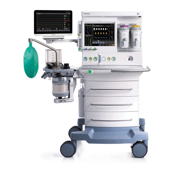
Page 39: Physical Views
Yellow = medium priority, Cyan = low priority, Off = no alarm condition. LCD Touchscreen Display / See section ‘‘System Interface’’ on page 3-1 System Interface Auxiliary O /Air Flowmeters Auxiliary O /Air Flowmeters for auxiliary O /Air output A7™ Operating Instructions 046-004667-00 1 - 9... - Page 40 Wheels Casters to enable the A7 System to be moved. Casters on the A7 lock via a central brake. Work Light Located under the top shelf to illuminate the work level shelf and allow the user to read the vaporizer dial setting in a dim light room.
- Page 41 Indicate the pressure at cylinder inlets for O , Air, and N Battery Charging LED Illuminated when the battery supply is charging. Handle Metal bar used to assist moving the A7 Key lock Key and lock for securing the drawers Storage Drawers Drawers (3) for storage (lockable) A7™...
-
Page 42: Main Unit (Rear View)
3 A each (quantity 4), 10 A total (quantity 1) Mains Inlet Connects the mains power cord Exhaust Fan Forces air to cool electronics and prevent buildup of O concentration. Do not block. 1 - 12 046-004667-00 A7™ Operating Instructions... - Page 43 Additional devices up to a total maximum power of 10 amps can be connected to four (4) outlets. The A7 outlets are covered with two (2) metal plates, and require a tool to access. Only authorized personnel can access these outlets.
-
Page 44: Main Unit (Left View)
Rail Mount Enables mounting of patient monitors and most standard attachment arms for other devices. Rail mounts are on both left and right sides of the A7. Module slot AG module mentioned in this manual can be inserted into the slot and identified. -
Page 45: Main Unit (Right View)
Storage Drawers Drawers (3) for storage (lockable) Rail Mount Enables mounting of patient monitors and most standard attachment arms for other devices. Rail mounts are on both left and right sides of the A7. A7™ Operating Instructions 046-004667-00 1 - 15... -
Page 46: Main Unit (Top View)
Top level surface Work Level Shelf Work Level surface (stainless steel) Handle Wrap-around metal bar used to assist moving the A7 device Mounting Holes Allows mounting of optional equipment to the top shelf (i.e., DPM6 and DPM7 mounting plates and kits (see section A.7 (page A-3) "Mounting Accessories"). -
Page 47: Breathing System (Top View)
Tidal volume (Vt) should be read exclusively from the display of the user interface. Delivered Vt is a combination of bellows displacement and fresh gas flow. The APL valve and PAW gauge numerics are for reference only. Calibrated patient airway pressure is dis- played on the user interface. A7™ Operating Instructions 046-004667-00 1 - 17... -
Page 48: Breathing System (Left View)
The APL valve and PAW gauge numerics are for reference only. Calibrated patient airway pressure is dis- played on the user interface. 1.2.7 Breathing System (Left View) FIGURE 1-8 Breathing System (Left View, the Flexible Bag Arm (optional)) 1 - 18 046-004667-00 A7™ Operating Instructions... - Page 49 360°. Fixed Height Bag Arm Provides the interface for the manual ventilation bag. The height of fixed bag arm cannot be adjusted and the bag port is in a fixed direction. A7™ Operating Instructions 046-004667-00 1 - 19...
-
Page 50: Active Anesthetic Gas Scavenging System (Agss) (Top, Right, And Rear Views)
Exhaust port to the hospital’s waste gas scavenging system Inlet Port Intake for exhaust gases from the breathing system. An AGSS transfer hose connects the Inlet and AGSS ports (see FIGURE 1-3) to transfer the exhaust gases. 1 - 20 046-004667-00 A7™ Operating Instructions... -
Page 51: Passive Anesthetic Gas Scavenging System (Agss) (Right View)
Intake for exhaust gases from the breathing system connecting with the AGSS ports. Exhaust Port Exhaust port to the hospital’s waste gas scavenging system. Manual Bag When the manual bag is inflated, it indicates that the passive AGSS is blocked. A7™ Operating Instructions 046-004667-00 1 - 21... -
Page 52: Negative Pressure Suction Device
REG indicates that the negative pressure suction device works with the pressure adjusted through the negative pressure adjustment knob. Turn the knob counterclockwise to increase negative pressure and clockwise to decrease the negative pressure. 1 - 22 046-004667-00 A7™ Operating Instructions... -
Page 53: Installation
Installation Unpacking........................................2-3 Initial Setup........................................2-4 Install the Vaporizer ....................................2-5 Install the Suction Canister .................................2-8 A7™ Operating Instructions 046-004667-00 2 - 1... - Page 54 WARNING: When electrosurgical equipment is used, keep the electrosurgical leads away from the breathing system, and other parts of the A7 Anesthesia System. Keep available backup manual ventilation and a respirator with mask in case the electrosurgical equipment prevents safe use of the ventilator.
-
Page 55: Unpacking
If there is NO damage and ALL tip indicators on the box exterior are intact, then sign and date the bill of lading or airway bill to indicate safe receipt of the A7. b. If there is DAMAGE or ANY of the tip indicators on the box exterior have been activated, then conditionally accept the delivery and clearly describe the damages on the bill of lading or airway bill. -
Page 56: Initial Setup
Initial Setup Installation Initial Setup The initial setup of the A7 Anesthesia System must be performed by an authorized Mindray service representative. Please contact Mindray Technical Support for any additional assistance. NOTE: The A7 is intended to be operated with an external CO2 monitor complying with ISO 80601-2-55. -
Page 57: Install The Vaporizer
Installation Install the Vaporizer Install the Vaporizer CAUTION: Only use vaporizers with Selectatec Interlock Systems with the A7 unit. WARNING: Use vaporizers compliant to ISO 80601-2-13. See section A.9 (page A-4) "Vaporizers". Refer to the vaporizer manufacturer’s Instructions For Use for mounting, filling, or draining the vaporizer and other information. - Page 58 WARNING: For the A7 Anesthesia System, using or turning on more than one vaporizer simultaneously is prohibited and prevented by a mechanical interlock. Do not attempt to override this safety mechanism.
-
Page 59: Filling And Draining The Vaporizer
Install the vaporizers with a Selectatec interlock system that are compliant to ISO 80601-2-13 on the A7 unit. See section A.9 (page A-4) "Vaporizers". Refer to the vaporizer manufacturer’s Instructions For Use for filling or draining the vaporizer and other information. -
Page 60: Install The Suction Canister
REGULATE MODE Turn selector knob fully clockwise to the regulator mode and confirm vacuum setting before use. FULL MODE Turn selector knob fully counterclockwise to the full mode and confirm vacuum setting before use. 2 - 8 046-004667-00 A7™ Operating Instructions... -
Page 61: Turn On The Vacuum Regulator
Turn Off the Negative Pressure Suction Device Switch the negative pressure suction selector to OFF to turn off the negative pressure suction device. WARNING: Keep the negative pressure suction switch in OFF status when not in use. A7™ Operating Instructions 046-004667-00 2 - 9... - Page 62 Install the Suction Canister Installation This page intentionally left blank. 2 - 10 046-004667-00 A7™ Operating Instructions...
-
Page 63: System Interface
Waveforms Tab......................................3-16 Spirometry Tab ......................................3-18 Demographics Tab....................................3-24 Ventilation Mode Tabs ..................................3-25 Measured Values Area..................................3-27 System Softkeys...................................... 3-28 List Trends........................................3-28 General Tab........................................ 3-36 Display Tab........................................3-38 System Tab.........................................3-42 Service Tab......................................... 3-49 A7™ Operating Instructions 046-004667-00 3 - 1... -
Page 64: Main Screen Components
Patient Size Displays the currently selected patient size (Adult, Pediatric, or Infant). Select to change the patient size when the A7 is in the Standby mode, Manual mode or Monitor* mode. Current Ventilation Mode Displays the current ventilation mode (VCV, SIMV-VC, PCV, SIMV-PC, PS, Manual, Bypass, ACGO, Monitor, or Standby.) - Page 65 Displays real-time agent usage per hour, cost per hour, Area flowmeter levels for O and balance gas. Waveforms/Spirometry Area Displays waveforms or spirometry. Monitored Parameter Area Displays monitored parameters. * Monitor mode is only available with the AG module. A7™ Operating Instructions 046-004667-00 3 - 3...
-
Page 66: System Information Header
When the countdown timer is expired, the system will pop-up a warning dialog (see FIGURE 3-5) and provide a notification sound at the same time, The sound will repeat until the Done button is pressed. 3 - 4 046-004667-00 A7™ Operating Instructions... -
Page 67: Patient Size
Patient Size Displays the currently selected patient size (Adult, Pediatric, or Infant). Select to change the patient size when the A7 is in Standby mode, Manual mode or Monitor mode (available with the AG module) (see FIGURE 3-7). Patient Size FIGURE 3-7 Patient Size Menu 3.2.3... -
Page 68: Alarm Silence Icon
The Alarm Silence icon and Alarm Silence countdown timer are displayed after selecting the Silence softkey, which indicates that all currently sounding alarms are silenced for 120 seconds (see FIGURE 3- Alarm Silence Icon FIGURE 3-9 Alarm Silence Icon 3 - 6 046-004667-00 A7™ Operating Instructions... -
Page 69: Date And Time
Daylight Savings setting has been set to Auto in the System settings (see TABLE 3-10 on page 3-42). 3. Select Accept to finalize your changes. FIGURE 3-11 Date and Time Menu A7™ Operating Instructions 046-004667-00 3 - 7... -
Page 70: Battery Status
System Interface 3.2.6 Battery Status Displays the main power supply and battery state (see FIGURE 3-12). For more information on the A7 advanced power management system, see “Power Management / Battery Supply” on page 1-6. Battery Status Icon FIGURE 3-12 Battery Status Icon... -
Page 71: Fresh Gas Flow Display
The flowmeter numerics display a precision to two decimal digits for flows < 1 L/min and one decimal digit for flows ≥ 1 L/min. The A7 System flowmeter is electronically controlled by the Electronic Flow Control System (hereinafter referred to as EFCS). -
Page 72: Direct Flow Control Mode
Displays O flow Flow indicator, showing the relationship between your set flow value and the optimal value. flow Flow of balance gas FIGURE 3-16 Electronic Flow Control System in Direct Flow Control Mode 3 - 10 046-004667-00 A7™ Operating Instructions... -
Page 73: Fresh Gas Flow Optimizer® (Software Bundle Version 02.09.00 And Later)
OPTIMIZER is defined as a range with a lower bound of "Fresh Gas Consumption" and an upper bound of "Fresh Gas Consumption + 1 L/min". Fresh gas consumption of the subject A7 depends on: • the uptake by the patient, •... - Page 74 Total fresh gas delivery is more than 1 L/min above the gas consumption (leak+uptake). EFFICIENT Green Total fresh gas delivery is efficient. NOTE: EFFICIENT does not imply clinical efficiency. Total fresh gas delivery is less than the gas consumption (leak+uptake). TABLE 3-1 Indication 3 - 12 046-004667-00 A7™ Operating Instructions...
- Page 75 AG Zero Failed • External AG Module Disconnected • Incompatible AG Software Version ® OPTIMIZER Inactive FIGURE 3-20 Inactive ® OPTIMIZER NOTE: If fresh gas data is unavailable, the ® will be OPTIMIZER ineffective. A7™ Operating Instructions 046-004667-00 3 - 13...
-
Page 76: Flow Pause (Software Bundle Version 02.09.00 And Later)
Select End Flow Pause button to exit the Flow Pause state. • The system exits the Flow Pause state automatically when the system enters Standby mode or the BFCS is enabled. After the system exits the Flow Pause state: 3 - 14 046-004667-00 A7™ Operating Instructions... -
Page 77: Backup Flow Control System
3.3.3 Backup Flow Control System When the A7 System detects a failure related to the EFCS, then the backup flow control system (hereinafter referred to as BFCS) automatically deploys and the total flow rotameter illuminates. If the BFCS is deployed due to a failure, contact a service personnel to disable the BFCS. -
Page 78: Waveforms Tab
If the measured value of Paw, Flow, or Volume is less than the boundary minus a margin at the end of two continuous breath cycles, the A7 System auto scales the waveform at the beginning of the next breath cycle. -
Page 79: Waveforms Manual Scaling
O Scale 0-35 0-50 0-100 Des Scale 0.0-6.0 0.0-9.0 0.0-18.0 Sev Scale 0.0-2.0 0.0-4.0 0.0-8.0 Iso Scale 0.0-1.2 0.0-2.5 0.0-5.0 0.0-5.0 Hal Scale 0.0-1.2 0.0-2.5 Enf Scale 0.0-1.2 0.0-2.5 0.0-5.0 TABLE 3-2 Gas Scales A7™ Operating Instructions 046-004667-00 3 - 17... -
Page 80: Spirometry Tab
Displays separate looped graphs and waveforms (See FIGURE 3-24). You can press the button (see FIGURE 3-24) to only view the spirometry loop (see FIGURE 3-25). Spirometry Tab FIGURE 3-24 Spirometry and Waveforms 3 - 18 046-004667-00 A7™ Operating Instructions... - Page 81 System Interface Spirometry Tab You can press the button (see FIGURE 3-25) to see the spirometry loop and waveforms (see FIGURE 3-24). FIGURE 3-25 Spirometry: Pressure-Volume Loop FIGURE 3-26 Spirometry: Flow-Volume Loop A7™ Operating Instructions 046-004667-00 3 - 19...
-
Page 82: Loop Type
Select Loop Type to display pressure - volume loop, flow - volume loop or pressure-flow loop on the Spirometry screen. Default loop type is pressure - volume loop. Show Reference Review Loops Loop Type Save Loop FIGURE 3-28 Spirometry Softkeys: Loop Type, Show Reference, Save Loop, and Review Loops 3 - 20 046-004667-00 A7™ Operating Instructions... -
Page 83: Show Reference
NOTE: A reference loop can not be saved without first saving a baseline loop. The A7 System always makes the first saved loop as the baseline loop if no previous loops have been saved. Afterward, additional loops can be saved either as a baseline replacement or as a new reference loop. -
Page 84: Review Loops Button
Reference Loop Loop (small) Loop Selected Numeric Data Reference Area Loop (large) FIGURE 3-29 Review Loops window Numeric Data Area: Displays the numerical data associated with a saved baseline loop and saved reference loops. 3 - 22 046-004667-00 A7™ Operating Instructions... - Page 85 Ratio of Inspiratory time to Expiratory time (I:E) • Positive End Expiratory Pressure (PEEP) • Rate • Peak Inspiratory Pressure (PEAK) • Plateau Pressure (PLAT) • Mean Pressure (MEAN) • Dynamic Airway Compliance (Compl) • Airway Resistance (Raw) A7™ Operating Instructions 046-004667-00 3 - 23...
-
Page 86: Demographics Tab
EDITABLE FIELD COMMENT Patient ID Enter up to 30 characters per field. These fields are cleared when the case has ended or if the A7 is power cycled. First Name Last Name DOB (Date Of Birth) Enter the information from the virtual keypad. If the input is outside the accepted range, a prompt message is displayed. -
Page 87: Ventilation Mode Tabs
Ventilation Mode Tabs Ventilation Mode Tabs Displays tabs for all ventilation modes. Each tab displays the ventilation mode and its parameters. (FIGURE 3-31 to FIGURE 3-37) A7 ventilation modes: • Volume Control Ventilation (VCV) • Synchronized Intermittent Mandatory Ventilation with VC mode (SIMV-VC) •... - Page 88 FIGURE 3-33 Ventilation Mode: SIMV-VC FIGURE 3-34 Ventilation Mode: PCV FIGURE 3-35 Ventilation Mode: SIMV-PC FIGURE 3-36 Ventilation Mode: PS FIGURE 3-37 Ventilation Mode: Manual NOTE: Monitor mode available when external AG module connected. 3 - 26 046-004667-00 A7™ Operating Instructions...
-
Page 89: Measured Values Area
System Interface Measured Values Area Measured Values Area The Measured Values area is used to display the numerical data. (FIGURE 3-38) Measured Values Area FIGURE 3-38 Measured Values Area A7™ Operating Instructions 046-004667-00 3 - 27... -
Page 90: System Softkeys
System Interface System Softkeys The A7 System provides system softkeys at the bottom right of the main screen for direct access to the history menu, system setup and alarms menu, and for capturing events and silencing alarms (see FIGURE 3-39). - Page 91 BUTTON FUNCTION Moves the cursor one record back from its current position. Moves the cursor one record forward from its current position. A7™ Operating Instructions 046-004667-00 3 - 29...
- Page 92 Moves the scroll to the bottom most parameter from its current position. Previous Event Moves the cursor to the previous event from its current position. Next Event Moves the cursor to the next event from its current position. TABLE 3-4 3 - 30 046-004667-00 A7™ Operating Instructions...
-
Page 93: Graphic Trends
Every point on the curve corresponds to the parameter value at a specific time point. Graphic Trends tab displays end case event, captured event and parameter alarm event. Graphic trend data automatically displays in one minute intervals unless the zoom is selected. A7™ Operating Instructions 046-004667-00 3 - 31... - Page 94 An end case event occurred during this period. The parameter data of the time indicated by cursor. TABLE 3-5 NOTE: The Graphic Trends will be cleared after the anesthesia machine undergoes power failure or is turned off. 3 - 32 046-004667-00 A7™ Operating Instructions...
- Page 95 Moves the cursor down one parameter from its current position. TABLE 3-6 3.9.5.2.3 Zoom Zoom allows the trends to be displayed in one page in a specified time interval. Set Zoom to 5Min, 10Min, 15Min, 30Min, 1Hour, or 2Hour. A7™ Operating Instructions 046-004667-00 3 - 33...
-
Page 96: Event Log
NOTE: The Event log will be cleared after the anesthesia machine undergoes a power failure or is turned off. To view event log, contact Mindray Customer Service. 3.9.5.3.1 Navigating in Event Log The dialog navigation buttons are described in TABLE 3-7. - Page 97 3.9.5.3.2 Event Log Filter The Filter button displays the Event Log Entries trends similarly to the Event type. Set Filter to High, Medium, Low, Informational or All. The A7 displays the corresponding event based on your setting. 3.9.5.3.3 Event Log Export The Export button on the Event Log tab exports the contents of the event log to a USB mass storage device.
-
Page 98: General Tab
Leak Test / Compliance The Test Leak / Compliance button enables the A7 System to perform an automatic leak test and manual leak test, and calculates the compliance for the A7. - Page 99 General Tab After cycling power, the breathing system warmer will return to the default state. NOTE: The breathing system warmer is inactive when the A7 is powered by the battery supply. Zero Flow Meters To zero the flow meters, select the Zero Flow Meters button. Follow the on-screen instructions and prompts.
-
Page 100: Display Tab
2. In the Screen Brightness area, select the +/- buttons to adjust the screen brightness. 3. Select the Accept button to confirm the change, or select Cancel to discard the change. Select the buttons to adjust screen brightness. FIGURE 3-45 Display Tab > Screen Brightness Area 3 - 38 046-004667-00 A7™ Operating Instructions... - Page 101 The screen locks for 10 seconds for cleaning. Calibrate Touch To calibrate the LCD touch screen: 1. Select Setup softkey > Display tab. 2. Select the Calibrate Touch button. 3. Follow the on-screen instructions. A7™ Operating Instructions 046-004667-00 3 - 39...
- Page 102 4. Select the Accept button to confirm the change, or select the Cancel button to discard the change. Gas Scales To set the Gas scales: 1. Select Setup softkey > Display tab. 2. Select the Gas Scales button. 3 - 40 046-004667-00 A7™ Operating Instructions...
-
Page 103: Waveform Display
1. Select Setup softkey > Display tab. 2. Select the Waveform Display button. 3. Select the desired waveform. 4. Select the Accept button to confirm the change, or select the Cancel button to discard the change. A7™ Operating Instructions 046-004667-00 3 - 41... -
Page 104: System Tab
Select to calibrate the External AG Internal AG Module Module or Internal AG Module. Follow the screen instructions. Language ENGLISH (default) Select to set the user interface text CHINESE language. FRENCH SPANISH TABLE 3-10 System Tab Settings 3 - 42 046-004667-00 A7™ Operating Instructions... - Page 105 Select Import Defaults to import a copy of the defaults from the USB mass storage device if one has been inserted into an SB port at the rear of the A7 unit. Export Defaults Select Export Defaults to export a...
- Page 106 Daylight Savings (Default Select to set the Daylight Savings Time =Manual, Auto) (DST) to be adjusted automatically by the A7 System, or manually by the authorized administrator. If the region or country of installation does not observe DST, change this setting to Manual.
- Page 107 When turned off, event logs and all trends will not be deleted at the start of the case. TABLE 3-10 System Tab Settings A7™ Operating Instructions 046-004667-00 3 - 45...
- Page 108 Select to set the cost of the agent per NOTE: If cost is set to zero then the cost of the agent per ml will not be displayed. TABLE 3-10 System Tab Settings 3 - 46 046-004667-00 A7™ Operating Instructions...
-
Page 109: Network Configuration
FIGURE 3-49 Network Configuration Screen TABLE 3-11 lists the network settings and parameters. SETTINGS PARAMETERS This Machine Configure Ethernet Enter: • IP Address (default = 192.168.23.250) • Subnet (default = 255.255.255.0) • Default Gateway (default = [blank]) A7™ Operating Instructions 046-004667-00 3 - 47... - Page 110 Enabled when Protocol=HL7:10 Sec, 30 Sec, 1 Min (default), 5 Min, 30 Min, 1 Hour, 2 Hour, 6 Hour, 12 Hour, 24 Hour. NOTE: When Protocol is set to MR-WATO, the A7 can communicate with the patient monitor of Mindray through Benelink module of Mindray. NOTE:...
-
Page 111: Service Tab
Secondary Server IP Enter: Secondary Server IP (default = 210.72.145.44) TABLE 3-11 Network Configuration Settings and Parameters 3.13 Service Tab Accessible only by Mindray-authorized service personnel. Please contact Mindray Technical Support for assistance. A7™ Operating Instructions 046-004667-00 3 - 49... - Page 112 Service Tab System Interface This page intentionally left blank. 3 - 50 046-004667-00 A7™ Operating Instructions...
-
Page 113: Preoperative Tests
Flow Control System Test.................................. 4-22 Vaporizer Tests ......................................4-23 Breathing System Tests ..................................4-25 Alarm Tests......................................... 4-27 Preoperative Preparations ................................4-29 Inspect the Active AGSS ..................................4-30 Inspect the Negative Pressure Suction Device ........................4-30 A7™ Operating Instructions 046-004667-00 4 - 1... -
Page 114: Preoperative Test Schedules
Preoperative Test Schedules Preoperative Tests Preoperative Test Schedules Preoperative tests on the A7 follow the ASA guidelines and should be performed according to the test intervals listed below. Refer to special procedures or precautions in this manual. NOTE: This is a guideline which can be modified to accommodate variations in local clinical practice. -
Page 115: Inspect The System
14. The AC mains indicator and the battery indicator are displayed when the power cord is connected to the AC power source. If the indicators are not displayed, the system does not have electrical power. 15. The A7 anesthesia machine is switched on or off normally. A7™ Operating Instructions 046-004667-00... -
Page 116: Pre-Operative Checkout List
An effective method for detecting pneumatic circuit occlusions, leaks, and other system problems can be found in the A7 pre-operative checkout procedures. In addition, it is recommended that the breathing circuit be tested for the ability to effectively deliver positive pressure ventilation before beginning each case. - Page 117 O manual leak test. Set the vaporizer to OFF. Repeat for the right vaporizer if installed (see “Manual Leak Test” on page 4-24). 5. Perform a vaporizer leak test for each vaporizer installed on the A7 System (see “Vaporizer Leak Test” on page 4-24).
-
Page 118: System Self-Test
Preoperative Tests System Self-Test When the A7 is powered on, it performs a self-test to ensure its alarm system (alarm LED, speaker, and buzzer) and hardware (flowmeter board, ventilator board, assistant ventilator board, power board, and CPU board) are properly functioning. - Page 119 Bundle Version – The Bundle Version is displayed in all System Self-Test results. The Bundle Version is the version number of the package of software that is installed in the A7. If the Bundle Version displays a fail status, contact Mindray Technical Support.
-
Page 120: Leak And Compliance Tests
1. From power up: While powering on the A7, the system automatically initiates a self-test and enters the Preoperative Check List screen. Select Continue to enter the Automatic Circuit Leak Test screen, followed by the Manual Circuit Leak Test screen. If the Skip button is selected, the system bypasses the Automatic Circuit Leak Test and the Manual Circuit Leak Test and enters the Standby mode. - Page 121 Auto position and when no fresh gas is detected. 3. Compare the test results with the information in TABLE 4-3, “Automatic Circuit Leak and Compliance Test Results, ” on page 4-10, and proceed accordingly. A7™ Operating Instructions 046-004667-00 4 - 9...
- Page 122 Select Accept to proceed to the Manual Circuit Leak Test screen and use the previous compliance values. Select Retry to repeat the Automatic Circuit Leak Test & Compliance test. TABLE 4-3 Automatic Circuit Leak and Compliance Test Results 4 - 10 046-004667-00 A7™ Operating Instructions...
- Page 123 Contact service if this error condition persists. NOTE: The Service Access button is only available to Mindray-authorized service personnel and requires a service password. TABLE 4-3 Automatic Circuit Leak and Compliance Test Results A7™ Operating Instructions 046-004667-00 4 - 11...
- Page 124 Select Retry to repeat the Automatic Circuit Leak Test & Compliance test. Select Override to skip the test. Backup Flow Control Enabled For the A7 System, the backup flow control is active. Example Follow on-screen instructions to troubleshoot the problem.
-
Page 125: Manual Circuit Leak Test
1. From power up: While powering on A7, the system automatically initiates a self-test and enters the Preoperative Check List screen. Select Continue to enter the Automatic Circuit Leak and Compliance Test and theManual Circuit Leak Test. If the Skip button is selected, the system bypasses these tests and enters the Standby mode. - Page 126 Fresh gas is not detected. Follow on-screen instructions to troubleshoot the issue. Adjust APL valve to the SP position and select Accept to proceed to the main screen. TABLE 4-4 Manual Circuit Leak Test Results 4 - 14 046-004667-00 A7™ Operating Instructions...
- Page 127 If this anomaly occurs, press the Cancel button on the screen to continue. Select Accept to proceed. Backup Flow Control Enabled For the A7 System, the backup flow control is active. Example Follow on-screen instructions to troubleshoot the problem.
-
Page 128: Automatic Backup Flow Control Test
FIGURE 4-3 Automatic Backup Flow Control Test To Perform an Automatic Backup Flow Control Test: 1. While powering on the A7, the system calculates the time between the last successful Automatic Backup Flow Control Test time and current time. If the difference between the... - Page 129 Select Continue to proceed to the main screen. Fail Automatic Backup Flow Control Test failed. Example: Select Retry to repeat the test. Select Accept to proceed without Automatic Backup Flow Control deployment. TABLE 4-5 Automatic Backup Flow Control Test A7™ Operating Instructions 046-004667-00 4 - 17...
-
Page 130: Preoperative Check List (Software Bundle Version 02.09.00 And Later)
Preoperative Check List (software bundle version 02.09.00 and later) While powering on the A7, the system automatically initiates a self-test and enters the Preoperative Check List screen. Select Continue to proceed to Standby mode. The Preoperative Check List screen is displayed in FIGURE 4-4. -
Page 131: Power Failure Alarm Test
4.9.1 Pipeline Test 1. Connect the O pipeline supply. 2. Close all cylinder valves if the A7 anesthesia machine is equipped with cylinders. 3. Set the system switch to the ON position. 4. Set the O flow to 6 L/min. -
Page 132: Air Pipeline Test
1. Connect the Air pipeline supply. 2. Close all cylinder valves if the A7 anesthesia machine is equipped with cylinders. 3. Set the system switch to the ON position. 4. Select Setup softkey > General tab and set the Fresh Gas Control to Direct Flow. -
Page 133: Cylinder Tests
Cylinder Tests 4.11 Cylinder Tests NOTE: You do not need to perform cylinder tests if the A7 anesthesia machine is not equipped with cylinders. 4.11.1 Check the Cylinder Pressure 1. Set the system switch to the OFF position and connect the cylinders to be checked. -
Page 134: Flow Control System Test
14. After checking that the BFCS is deployed, visually check the total flowmeter for basal flow of approximately 1 L/min. 15. Adjust the Air needle valve. Increase Air flow gradually and check that the total flow continues to rise to more than 10 L/min. Close the Air needle valve. 4 - 22 046-004667-00 A7™ Operating Instructions... -
Page 135: Vaporizer Tests
1 L/min through the full range. Otherwise, install a different vaporizer and repeat this step. If the problem persists, the malfunction is in the anesthesia system. Do not use this system. 5. Test each vaporizer as per the steps above. A7™ Operating Instructions 046-004667-00 4 - 23... -
Page 136: Manual Leak Test
6. Set the APL valve to 75 and verify that the pressure on the airway pressure gauge increases above 30 cmH O within 2 minutes. 7. Turn off the vaporizer. 8. Repeat steps 4, 5, 6, and 7 for the other vaporizer. 4 - 24 046-004667-00 A7™ Operating Instructions... -
Page 137: Breathing System Tests
25 and 35 9. Release the O flush button. A pressure decrease on the airway pressure gauge indicates a leak. Contact your service personnel. A7™ Operating Instructions 046-004667-00 4 - 25... -
Page 138: Apl Valve Test
Ensure that the reading on the airway pressure gauge does not exceed 10 cmH 13. Turn the O flow to zero. Ensure that the reading on the airway pressure gauge does not decrease below 0 cmH 4 - 26 046-004667-00 A7™ Operating Instructions... -
Page 139: Alarm Tests
Preoperative Tests Alarm Tests 4.15 Alarm Tests Test alarms by creating an alarm condition on the A7 and verifying the corresponding alarm indicators are present on the monitor. 4.15.1 Prepare for Alarm Tests 1. Connect a test lung or manual bag to the Y-piece of the breathing circuit. -
Page 140: Test The O Concentration Monitoring And Alarms
3. Turn the APL valve control to set the APL valve to 10 cmH 4. Inflate using the O flush button and squeeze the manual bag to check that a complete breathing cycle occurs on screen. 4 - 28 046-004667-00 A7™ Operating Instructions... -
Page 141: Test The Continuous Airway Pressure Alarm
3. Ensure that the equipment for airway maintenance, manual ventilation and tracheal intubation, and applicable anesthetic and emergency drugs are available. 4. Set the Auto/Manual ventilation switch to Manual. 5. Connect the manual bag to the manual bag port. 6. Turn off all vaporizers. A7™ Operating Instructions 046-004667-00 4 - 29... -
Page 142: Inspect The Active Agss
8. Set all gas flows to zero. 9. Ensure that the breathing system is correctly connected and not damaged. WARNING: Before connecting a patient, flush the A7 anesthesia machine with 8 L/ min of O for at least two minutes. This removes unwanted mixtures and by-products from the system. -
Page 143: Operations
Operations Powering On the A7 Anesthesia System............................5-2 Powering Off the A7 Anesthesia System ...........................5-2 Patient Setup .......................................5-3 Input Fresh Gas ......................................5-5 Input Fresh Gas ......................................5-5 Ventilation Modes ....................................5-7 Start Mechanical Ventilation................................5-18 Stop Mechanical Ventilation................................5-18 Relationships of Ventilation Parameters ..........................5-18 Parameter Monitoring (Numerics) .............................. -
Page 144: Powering On The A7 Anesthesia System
The A7 System provides a powering off function with the following features: • A prompt tone is heard when the user turns off the A7. If the system switch is turned off in Standby mode, the A7 will immediately power off. -
Page 145: Patient Setup
If the Restore default settings checkbox is not selected, all the settings are retained. FIGURE 5-3 End Case Checkbox In the Standby mode, all system functions are not working. It is the default system startup mode and is used after ending the case. A7™ Operating Instructions 046-004667-00 5 - 3... - Page 146 1. Set the Auto/Manual ventilation switch to Manual. NOTE: The A7 System will not allow the End Case button to be selected until the Auto/Manual ventilation switch is set to Manual. 2. Select the End Case button in the Manual tab (see FIGURE 5-2).
-
Page 147: Select The Patient Size (Adult, Pediatric, Infant)
EFCS or set the O and Air flow through BFCS. Safety systems within the A7 work to prevent hypoxic mixtures from being delivered to the patient. Nitrous oxide will not be delivered unless oxygen flow is present. -
Page 148: Set Anesthetic Agent
The concentration of the anesthetic agent actually output varies if the vaporizer is filled with the wrong agent. 2. Mount the vaporizer filled with anesthetic agent onto the A7 Anesthesia System. See “Install the Vaporizer” on page 2-5. 5.4.2.2... -
Page 149: Ventilation Modes
When the drive gas supply fails, mechanical ventilation cannot work normally. 5.5.1 Monitored Parameters NOTE: The monitored parameters are measured in the condition of ATPS (ambient temperature and pressure saturated). The A7 monitors the following ventilation parameters: PARAMETER RANGE* COMMENTS PEAK -20 –120 cmH MEAN -20 –... -
Page 150: Set Manual Ventilation Mode
Manual to Auto and back to Manual mode. For example, if the Alarms button is set to Off, this setting will be saved and restored to Off after switching to Auto and back to Manual mode. FIGURE 5-7 Alarm Limit Indicators 5 - 8 046-004667-00 A7™ Operating Instructions... - Page 151 Alarms softkey to Off. The related alarm limits are then displayed as Off. Pressure, volume and apnea alarms can be turned on by setting the Alarms softkey to On, which returns the related alarm limits to their original settings. A7™ Operating Instructions 046-004667-00 5 - 9...
-
Page 152: Make Settings Before Starting Mechanical Ventilation Mode
This is called tidal volume compensation. 5 - 10 046-004667-00 A7™ Operating Instructions... -
Page 153: To Set Vcv Mode
Operations Ventilation Modes In the VCV mode, if tidal volume compensation has failed, the A7 Anesthesia System can continue delivering gas stably but cannot compensate for the effects of fresh gas flow and breathing system compliance losses. In VCV and SIMV-VC modes, when inspiration pressure reaches Plimit, respectively, the inspiration pressure is held. -
Page 154: To Set Pcv Mode
Ventilation Modes Operations For the A7, in PCV mode, Tidal Volume Guarantee (VtG) can be enabled with the VtG setting. When VtG is a value, then Pinsp is disabled. The ventilator attempts to deliver the set VtG while maintaining the PAW at or below PlimVG. When VtG is Off, PlimVG is disabled and Pinsp is enabled. -
Page 155: Pressure Support In Synchronized Intermittent Mandatory Ventilation (Simv)
Spontaneous breathing outside trigger window can acquire pressure support. In VCV and SIMV-VC modes, when inspiration pressure reaches Plimit, the inspiration pressure is held. 5.5.8.3 Synchronized Intermittent Mandatory Ventilation–Pressure Control (SIMV-PC) FIGURE 5-13 Synchronized Intermittent Mandatory Ventilation–Pressure Control (SIMV-PC) A7™ Operating Instructions 046-004667-00 5 - 13... -
Page 156: To Set Simv-Vc Or Simv-Pc Mode
SIMV-PC parameters: • Pinsp: Peak inspiratory airway pressure • Rate: Breath rate • Tinsp: Time of inspiration NOTE: The screen displays the calculated I:E ratio based on Rate and Tinsp when adjusting the Tinsp. 5 - 14 046-004667-00 A7™ Operating Instructions... -
Page 157: Pressure Support Ventilation (Ps)
5.5.9 Pressure Support Ventilation (PS) In Pressure Support (PS) mode, the patient’s effort is supported by the A7 at a preset level of inspiratory pressure. Inspiration is triggered and cycled by patient effort. The user can set the Trigger flow, ΔP, PEEP, minimum allowed breathing frequency, and Slope Time. -
Page 158: Auxiliary Common Gas Outlet (Acgo) Mode
Monitor Mode Monitor mode is only available in the Manual ventilation mode when there is an AG module connected to the A7. This mode turns off all ventilation related alarms. NOTE: When Monitor mode is On, the Alarms button is disabled and set to Off. - Page 159 Waveforms tab. The Rate as determined by the AG module displays in the measured values area. The current mode area displays Monitor when Monitor is On. FIGURE 5-17 Monitor Mode A7™ Operating Instructions 046-004667-00 5 - 17...
-
Page 160: Start Mechanical Ventilation
1. Set the Auto/Manual ventilation switch to Manual. 2. Exit Standby by touching the main screen or by turning on the fresh gas. 3. Set the Auto/Manual ventilation switch to Auto. The A7 System begins mechanical ventilation. Stop Mechanical Ventilation To stop mechanical ventilation: 1. -
Page 161: Volume
If the parameter data is out of range, it displays as “– – –”. NOTE: The high alarm limit is displayed to the top right of the reading. The low alarm limit is displayed to the bottom right of the reading. A7™ Operating Instructions 046-004667-00 5 - 19... -
Page 162: Parameter Monitoring (Waveforms)
5.10.1.1 Auto-zeroing the Pressure Sensors The A7 auto-zeros the pressure sensors at regular intervals to compensate for changes in temperature and/or barometric pressure that could affect both pressure and flow measurements. This may affect the waveforms on the screen, but does not affect the volume/pressure delivered to the patient. -
Page 163: Volume Waveform
Though the X-axis is not labeled, it represents a time scale of 0 to 15 seconds. 5.10.4 Gas Waveform The CO vs. Time waveform displays in the waveform area. FIGURE 5-24 Example Simulated CO vs. Time Waveform A7™ Operating Instructions 046-004667-00 5 - 21... - Page 164 Y-axis (see “Gas Scales” on page 3-40). Though the X-axis is not labeled, it represents a time scale of 0 to 15 seconds. AA vs. Time waveform is displayed in the waveform area. FIGURE 5-27 Example Simulated AA vs. Time Waveform (available with the AG module) 5 - 22 046-004667-00 A7™ Operating Instructions...
-
Page 165: Waveform Autoscaling
Currently plotting loop, reference loop, and baseline loop display in manual and mechanical ventilation modes. Discharging the patient clears spirometry loops (baseline and reference loops). Restarting the machine clears spirometry loops (baseline and reference loops). A7™ Operating Instructions 046-004667-00 5 - 23... - Page 166 Flow - Volume Spirometry Loop FIGURE 5-30 is an example of the Flow - Volume loop. FIGURE 5-30 Flow - Volume Loop The Y-axis of the Flow - Volume Spirometry loop represents Flow. The X-axis represents Volume. 5 - 24 046-004667-00 A7™ Operating Instructions...
- Page 167 FIGURE 5-31 is an example of the Pressure - Flow loop. FIGURE 5-31 Pressure - Flow Loop The Y-axis of the Pressure - Flow Spirometry loop labeled PAW represents airway pressure. The X- axis represents Flow. A7™ Operating Instructions 046-004667-00 5 - 25...
- Page 168 Parameter Monitoring (Spirometry) Operations This page intentionally left blank. 5 - 26 046-004667-00 A7™ Operating Instructions...
- Page 169 Alarms and Messages Introduction .........................................6-2 Displaying Alarms.....................................6-5 Setting Alarm Volume....................................6-7 Silencing Alarms......................................6-8 Alarm Limits .........................................6-9 Alarm and Prompt Messages ................................. 6-14 A7™ Operating Instructions 046-004667-00 6 - 1...
-
Page 170: Alarms And Messages
Alarms and Messages Introduction The A7 System provides alarms and messages that are indicated to the user by visual and audible alerts. Alarms and messages display at the top of the main screen and in the Alarms window (see FIGURE 6-1). Users can adjust alarm properties, which include setting alarm limits to trigger alarm conditions, adjusting alarm volume, and silencing alarms. -
Page 171: Types Of Alarms And Messages
Alarms and Messages Introduction 6.1.2 Types of Alarms and Messages The A7 provides the following types of alarms and messages below. See section 6.6 (page 6-14) "Alarm and Prompt Messages" for the list of alarms and messages: • Physiological Alarm: Patient-related variables cause physiological alarms. -
Page 172: Alarm Indicators
Introduction Alarms and Messages 6.1.3 Alarm Indicators The A7 provides the following alarm indicators: • An alarm LED located on top of the LCD monitor. The LED can illuminate red, yellow, cyan, or OFF depending on the alarm condition. Table describes the alarm behavior of different alarm types and different alarm priority labels. If multiple alarms occur simultaneously, the audio and LED behavior follows the highest priority active alarm. -
Page 173: Displaying Alarms
Alarms display in order of priority and time. See section 6.2.1 (page 6-6) "Displayed Order of Alarm Messages" for more information. FIGURE 6-2 Active Alarms list in the Alarms window A7™ Operating Instructions 046-004667-00 6 - 5... -
Page 174: Displayed Order Of Alarm Messages
In each group, the most recent alarm displays first. • If the alarm in Area A is removed, then the most recent and highest priority alarm from Area B is moved to Area A. 6 - 6 046-004667-00 A7™ Operating Instructions... -
Page 175: Setting Alarm Volume
FIGURE 6-4 Audio Tab WARNING: Do not rely exclusively on the audible alarm system when using the A7 Anesthesia System. Adjustment of alarm volume to a low level may result in a hazard to the patient. Always keep the patient under close surveillance. -
Page 176: Silencing Alarms
If this occurs, you can select the Silence softkey again to silence the new alarm and reset the silence countdown timer to 120 seconds. Alarm audio-paused Icon 120 second countdown time icon FIGURE 6-5 Alarm audio-paused 6 - 8 046-004667-00 A7™ Operating Instructions... -
Page 177: Alarm Limits
NOTE: When using the A7 Anesthesia System, ensure that the alarm limits of each parameter are set to the appropriate values for the patient. There are two ways to set alarm limits: 1. - Page 178 Alarm Limits Alarms and Messages FIGURE 6-6 Limits tab in the Alarms Window (without AG module connected) FIGURE 6-7 Limits tab in the Alarms Window (with AG module connected) 6 - 10 046-004667-00 A7™ Operating Instructions...
- Page 179 Alarms and Messages Alarm Limits FIGURE 6-8 Agents tab in the Alarms Window (with AG module connected) A7™ Operating Instructions 046-004667-00 6 - 11...
-
Page 180: Loading Alarm Defaults
Load Alarm Defaults button FIGURE 6-9 Load Alarm Defaults button in the Alarms window (without AG module connected) Load Alarm Defaults button FIGURE 6-10 Load Alarm Defaults button in the Alarms window (with AG module connected) 6 - 12 046-004667-00 A7™ Operating Instructions... -
Page 181: Auto Alarm Limits
The Auto Alarm Limits function uses an algorithm based on measured values. The relationship is shown in the TABLE 6-2. The Auto Alarm Limits button is disabled when the A7 is in Standby mode, Manual mode or Monitor mode. The Auto Alarm Limits button is also disabled when the current mode is PS, SIMV- VC, or SIMV-PC. -
Page 182: Alarm And Prompt Messages
The Disabled in Standby mode column indicates which physiological alarms will be automatically disabled in the Standby mode. NOTE: The Disabled in Monitor mode column indicates which physiological alarms will be automatically disabled in the Monitor mode. 6 - 14 046-004667-00 A7™ Operating Instructions... -
Page 183: Physiological Alarm Messages
O Too Low O < low alarm limit Medium setting N/A - Not Applicable. This alarm message does not exist within this mode and therefore cannot be disabled or enabled. TABLE 6-3 Physiological Alarm Messages A7™ Operating Instructions 046-004667-00 6 - 15... - Page 184 Too Low < low alarm limit Medium setting N/A - Not Applicable. This alarm message does not exist within this mode and therefore cannot be disabled or enabled. TABLE 6-3 Physiological Alarm Messages 6 - 16 046-004667-00 A7™ Operating Instructions...
-
Page 185: Technical Alarm Messages
“All” indicates that all Automatic Ventilation, Manual Ventilation, and Cardiac Bypass modes are enabled. “Only Manual” indicates that only Manual Ventilation and Cardiac Bypass modes are enabled. “Non-Functional” indicates that the A7 Anesthesia System cannot be used. MACHINE MODE STARTUP... - Page 186 Functional Control internal Board communication error. Ventilator 5 V or 12 V voltage High Startup Only Ventilator Voltage Error / error Manual Control Ventilator Board Voltage: Fail TABLE 6-4 Startup Alarm Messages 6 - 18 046-004667-00 A7™ Operating Instructions...
- Page 187 RT Clock Failure RT chip malfunction High Startup only CPU Board / RT Clock: Fail TABLE 6-4 Startup Alarm Messages A7™ Operating Instructions 046-004667-00 6 - 19...
-
Page 188: Cpu Board Runtime Alarm
Fan Failure Speed of the fan ≤ 20% of Medium Runtime normal speed Fan Failure O Speed of Module Rack Medium Runtime fan < 3640 TABLE 6-5 CPU Board Runtime Alarm Messages 6 - 20 046-004667-00 A7™ Operating Instructions... -
Page 189: Power Board Runtime Alarm
If the power board loses communication with the CPU board for 10 seconds, the alarm buzzer is turned on. NOTE: If the system restarts accidentally, the alarm buzzer will sound for 10 seconds to show notification. A7™ Operating Instructions 046-004667-00 6 - 21... -
Page 190: Flow Control System Runtime Alarm
Achieved %, 200 mlpm) N/A - Not Applicable. This alarm message does not exist within this mode and therefore cannot be disabled or enabled. TABLE 6-7 Electronic Flow Control System Runtime Alarm Messages 6 - 22 046-004667-00 A7™ Operating Instructions... -
Page 191: Ventilator Control Board Runtime Alarm
5 V or 12 V voltage error High Runtime Error N/A - Not Applicable. This alarm message does not exist within this mode and therefore cannot be disabled or enabled. TABLE 6-8 Ventilator Control Board Runtime Alarm Messages A7™ Operating Instructions 046-004667-00 6 - 23... - Page 192 Drive Gas Pressure is low. High Runtime N/A - Not Applicable. This alarm message does not exist within this mode and therefore cannot be disabled or enabled. TABLE 6-8 Ventilator Control Board Runtime Alarm Messages 6 - 24 046-004667-00 A7™ Operating Instructions...
-
Page 193: Anesthetic Gas (Ag) Module Alarm Messages
AG Comm Stop AG module malfunction High Runtime or communication failure. TABLE 6-9 AG Module Alarm Messages A7™ Operating Instructions 046-004667-00 6 - 25... - Page 194 O Over Range range. Hal Over Range Enf Over Range Iso Over Range Sev Over Range Des Over Range Over Range Rate Over Range TABLE 6-9 AG Module Alarm Messages 6 - 26 046-004667-00 A7™ Operating Instructions...
- Page 195 Internal AG Error Internal AG Zero Failed Internal AG Error Internal AG No Watertrap Internal AG Error Internal AG Airway Occluded Internal AG Error Internal AG Change Watertrap TABLE 6-9 AG Module Alarm Messages A7™ Operating Instructions 046-004667-00 6 - 27...
-
Page 196: Prompt Messages
This message displays when the Flow Pause is active. Gas Flow Paused All Physiological This message displays when the Flow Pause is active. Alarms are OFF TABLE 6-10 Prompt Messages Display in Alarm Area 6 - 28 046-004667-00 A7™ Operating Instructions... -
Page 197: Prompt Messages Displayed In Pop-Up Area
This message displays in the first Automatic Circuit Leak Test & Auto position. Compliance Test screen when pressing the disabled Continue button if EFCS is configured. TABLE 6-11 Prompt Messages Displayed in Pop-up Area A7™ Operating Instructions 046-004667-00 6 - 29... - Page 198 Cannot set Fresh Gas Flow This message displays when the user presses the fresh gas flow area in Monitor mode. or adjusts encoder knob in Monitor mode. TABLE 6-11 Prompt Messages Displayed in Pop-up Area 6 - 30 046-004667-00 A7™ Operating Instructions...
-
Page 199: Maintenance
Breathing System Maintenance...............................7-4 Flow Sensor Calibration ..................................7-5 Water Build-up in the Flow Sensor ..............................7-6 Water Build-up in the Flow Sensor ..............................7-6 AGSS Transfer Tube Maintenance..............................7-7 Electrical Safety Inspection.................................7-7 Cleaning and Disinfection...................................7-8 Regular Maintenance ..................................7-26 A7™ Operating Instructions 046-004667-00 7 - 1... - Page 200 Maintenance WARNING: Do not use a malfunctioning A7 Anesthesia System. Have all repairs and service done by an authorized service representative. WARNING: Use a cleaning and disinfection schedule that conforms to your institution's disinfection and risk-management policies. • Refer to the material safety data sheet as applicable.
-
Page 201: Theory Of Operation
Maintenance Theory of Operation Theory of Operation The A7 System is a pneumatically-driven and electronically-controlled anesthesia machine. Three types of supply gases are available: N O, O , and Air. The user adjusts supply gas flows through the flowmeters. The mixed gas outputted from the flowmeters is further mixed with the anesthetic agent inside the anesthetic vaporizer to form the fresh gas. -
Page 202: Maintenance Schedule
MAINTENANCE Daily Clean the external surfaces. Annually Perform periodic maintenance by a trained technician. Contact Mindray Technical Support for details. Every three years Perform periodic maintenance by a trained technician. Contact Mindray Technical Support for details. As necessary • Before installing the cylinder, use a new cylinder gasket on the cylinder yoke. -
Page 203: Flow Sensor Calibration
11. Select Done to close the Calibration window (see FIGURE 7-3). 12. Select the Accept or Cancel softkey to close the Setup window. NOTE: In case of repeated calibration failure, contact Mindray Technical Support. FIGURE 7-2 Flow Sensor Calibration FIGURE 7-3 Flow Sensor Calibration... -
Page 204: Water Build-Up In The Flow Sensor
Use a filter between the flow sensor and the patient to limit water condensation in the flow sensor. • Check the water trap for water before using the A7 Anesthesia System. If there is water build- up, clear it immediately. 7.6.2 Clear Water Build-up Water build-up inside the flow sensor results in inaccurate measured value of tidal volume. -
Page 205: Agss Transfer Tube Maintenance
Perform electrical safety inspection after servicing or routine maintenance. Before the electrical safety inspection, make sure all the covers, panels, and screws are correctly installed. NOTE: Perform the electrical safety inspection once a year. A7™ Operating Instructions 046-004667-00 7 - 7... -
Page 206: Cleaning And Disinfection
7.9.2 Cleaning and Disinfecting Agents / Autoclaving Clean and disinfect the A7 before its first use, then daily and as often as needed. (see TABLE 7-1, “Maintenance Schedule, ” on page 7-4.) TABLE 7-2 to TABLE 7-4 list the allowable cleaning and disinfecting agents and autoclaving process for the A7 Anesthesia System. - Page 207 All breathing system components are autoclavable except the PAW gauge, flow sensor, and bellows. The components can be autoclaved up to a maximum temperature of 134 ºC (273 ºF). The suction tubes of the negative pressure suction device are not autoclavable. TABLE 7-4 Autoclaving A7™ Operating Instructions 046-004667-00 7 - 9...
-
Page 208: External Surfaces
1. The bellows dome is a transparent cover with graduation marks from 300 to 1500 ml. Remove the bellows dome by turning it counterclockwise and lifting it away from the breathing system. (see FIGURE 7-5) FIGURE 7-5 Removing the Bellows Dome 7 - 10 046-004667-00 A7™ Operating Instructions... - Page 209 2. Detach the bellows from the base plate (see FIGURE 7-6). FIGURE 7-6 Detaching the Bellows 3. Detach the top plate from the bellows (see FIGURE 7-7). FIGURE 7-7 Detaching the Bellows Top Plate A7™ Operating Instructions 046-004667-00 7 - 11...
- Page 210 CAUTION: Do not autoclave the following components: Paw gauge, flow sensor, and bellows. These components cannot withstand immersion or the heat and pressure of autoclaving. 7 - 12 046-004667-00 A7™ Operating Instructions...
-
Page 211: Inspiration And Expiration Valves
The following procedure is written generically for a single, unspecified valve. It should be performed on both the inspiration and expiration valves. Expiration Valve Inspiration Valve FIGURE 7-10 Location of Expiration and Inspiration Valves A7™ Operating Instructions 046-004667-00 7 - 13... - Page 212 The valve disc in each of the inhalation and exhalation valve assemblies on the breathing system is fragile and must be handled with care while removing the valve cage from the valve assembly. 7 - 14 046-004667-00 A7™ Operating Instructions...
- Page 213 TION. Prior to use after cleaning or disinfecting, power up the system and follow the on- screen prompts to perform the leak test and the compliance test (see section 4.5 (page 4-8) "Leak and Compliance Tests"). A7™ Operating Instructions 046-004667-00 7 - 15...
-
Page 214: Apl Valve
Prior to use after cleaning or disinfecting, power up the system and follow the on-screen prompts to perform the leak test and the compliance test. see section 4.5 (page 4-8) "Leak and Compliance Tests". 7 - 16 046-004667-00 A7™ Operating Instructions... -
Page 215: Paw Gauge
3. Re-insert the PAW gauge if it was removed. Prior to use after cleaning or disinfecting, power up the system and follow the on-screen prompts to perform the leak test and the compliance test (see section 4.5 (page 4-8) "Leak and Compliance Tests"). A7™ Operating Instructions 046-004667-00 7 - 17... -
Page 216: Bag Arm
4. Reassemble the bag arm to the breathing system. Prior to use after cleaning or disinfecting, power up the system and follow the on-screen prompts to perform the leak test and the compliance test (see section 4.5 (page 4-8) "Leak and Compliance Tests"). 7 - 18 046-004667-00 A7™ Operating Instructions... -
Page 217: Absorber Canister
18). This separates the absorber canister from the top of the assembly. While noting the previous WARNING, remove the absorber canister. Then remove the Pre-Pak or loose fill absorbent from the canisters. Dispose of the absorbent as per the local regulations. A7™ Operating Instructions 046-004667-00 7 - 19... - Page 218 Use an approved disinfecting agent (see TABLE 7-3 on page 7-9 and TABLE 7-4 on page 7-9) for the absorber canister while adhering to facility policies and procedures. 6. Make sure that the gasket is correctly installed. The comparison between correct installation and incorrect installation is shown below. 7 - 20 046-004667-00 A7™ Operating Instructions...
- Page 219 (see FIGURE 7-19). Prior to use after cleaning or disinfecting, power up the system and follow the on-screen prompts to perform the leak test and the compliance test (see section 4.5 (page 4-8) "Leak and Compliance Tests"). A7™ Operating Instructions 046-004667-00 7 - 21...
-
Page 220: Breathing System Block
3. Press and hold the buckle on the bypass assembly to take out the bypass assembly downward. Buckle Bypass Assembly FIGURE 7-21 Remove Bypass Assembly 4. Pull out the canister bottom plate upward. Canister Bottom Plate FIGURE 7-22 Remove Canister Bottom Plate 7 - 22 046-004667-00 A7™ Operating Instructions... - Page 221 Clean the breathing system block exterior with a soft, lint-free cloth and a recommended cleaning agent (see TABLE 7-2 on page 7-8). Allow to dry thoroughly. b. If disinfecting the breathing system block, continue with step 7, otherwise skip to step 8. 7. Disinfection A7™ Operating Instructions 046-004667-00 7 - 23...
- Page 222 CAUTION: To ensure measurement accuracy and to avoid possible damage to the A7, use only Mindray-approved cables and accessories. CAUTION: Inspiratory and expiratory flow sensors are flow-direction-sensitive. 7 - 24 046-004667-00 A7™...
-
Page 223: Active Agss (Anesthetic Gas Scavenging System) And Agss Transfer Hose
Active AGSS (Anesthetic Gas Scavenging System) and AGSS Transfer Hose 1. Disconnect the EVAC hose from the AGSS (see FIGURE 7-25). 2. Remove the AGSS and Transfer Hose from the A7. Transfer Hose EVAC Hose Port FIGURE 7-25 AGSS and Transfer Hose Removal 3. -
Page 224: Regular Maintenance
Regular Maintenance Maintenance AGSS Filter FIGURE 7-26 Removal of AGSS Top / AGSS Filter Inspection 5. Reassemble the AGSS and Transfer Hose and reconnect them to the A7 in the reverse order. 7.10 Regular Maintenance WARNING: To avoid endangering a patient, do not perform testing or maintenance when the machine is in use. - Page 225 Understand MAC Values..................................8-3 Agent Usage Calculation ..................................8-4 Identify External AG Modules................................8-5 Prepare to Measure AG ..................................8-6 Make AG Settings......................................8-7 Measurement Limitations ...................................8-9 Troubleshooting......................................8-9 Sample Gas Recirculation ................................. 8-10 Calibrate the AG Module .................................. 8-11 A7™ Operating Instructions 046-004667-00 8 - 1...
-
Page 226: Ag And O2 Concentration Monitoring
2. Measured parameters: EtCO , FiCO , EtN O, FiN O, EtAA, FiAA and MAC, where, AA stands for any of the five anesthetic agents: Des (desflurane), Iso (isoflurane), Enf (enflurane), Sev (sevoflurane), or Hal (halothane). A7™ Operating Instructions 8 - 2 046-004667-00... -
Page 227: Understand Mac Values
U.S. Food and Drug Administration for a healthy 40- year-old male patient. NOTE: In actual applications, although the A7 accounts for patient age, the effects of weight and other factors on the inhaled anesthetic agent should be considered. -
Page 228: Agent Usage Calculation
A7 exits the Standby mode. When A7 enters Standby, the agent usage stops accumulating. If the A7 restarts within not more than 60s after accidental power failure, when the case is not ended, the anesthetic agent usage will continue accumulating until the A7 enters Standby mode. -
Page 229: Agent Consumption Speed (Software Bundle Version 02.11.00 Or Later)
Agent Consumption Speed (Software Bundle Version 02.11.00 or later) Agent Consumption Speed (Software Bundle Version 02.11.00 or later) When anesthesia system is configured with internal AG module, A7 can calculate the agent consumption speed (the approximately agent used per hour) and the cost. Agent Comsumption Speed... -
Page 230: Prepare To Measure Ag
Do not use high volume watertraps with Infant patients. Otherwise, patient injury could result. WARNING: Make sure that all connections are reliable. Any leak in the system can result in erroneous readings due to patient breathing gas mixed with ambient air. A7™ Operating Instructions 8 - 6 046-004667-00... -
Page 231: Make Ag Settings
Med: 150 ml/min for high volume watertrap; 90 ml/min for low volume watertrap Low: 120 ml/min for high volume watertrap; 70 ml/min for low volume watertrap 4. Select the Accept button to confirm the change, or select the Cancel button to disregard the change. A7™ Operating Instructions 046-004667-00 8 - 7... -
Page 232: Set Alarm Limits
The alarm is then triggered when the parameter value is greater than the High Limit or lesser than the Low Limit. NOTE: When using the A7 Anesthesia System, ensure that the alarm limits of each parameter are set to the appropriate values for the patient. To set the Alarm Limits: 1. -
Page 233: Measurement Limitations
If that does not resolve it, internal occlusions may exist. Contact your service personnel. If the expired O concentration is higher than the inspired O concentration, it is possible that the pump rate is too low. Setting Gas Bench Flow Rate to High is recommended. A7™ Operating Instructions 046-004667-00 8 - 9... -
Page 234: Sample Gas Recirculation
When using the AG module to perform AG measurements on the patients who are receiving or have recently received anesthetic agents, connect the outlet to the sample gas return port to prevent the medical staff from breathing in the anesthetic agents. A7™ Operating Instructions 8 - 10 046-004667-00... -
Page 235: Calibrate The Ag Module
10. After calibration, select the Done botton to close the Calibration window. 11. Select the Accept button to confirm the change, or select the Cancel button to discard the change. A7™ Operating Instructions 046-004667-00 8 - 11... - Page 236 Calibrate the AG Module AG and O2 Concentration Monitoring This page intentionally left blank. A7™ Operating Instructions 8 - 12 046-004667-00...
-
Page 237: Product Specifications
Ventilator Specifications ...................................9-18 Displays and Controls Specifications............................9-20 Alarms ........................................... 9-22 Safety Specifications .................................... 9-22 ASTM F 1208 – 89 (2005) Disclosures............................9-23 Data Storage (Non-Volatile) and Recording.......................... 9-24 Electromagnetic Compatibility ..............................9-26 A7™ Operating Instructions 046-004667-00 9 - 1... -
Page 238: Standards Compliance
Standards Compliance Product Specifications Standards Compliance The A7 Anesthesia System is in compliance with the following industry standards. ANSI / AAMI ES60601-1:2005/(R)2012 and Medical electrical equipment - Part 1: General requirements C1:2009/(R)2012 and, A2:2010/(R)2012 for basic safety and essential performance... -
Page 239: Safety Designations
Equipment designed for non-electrical connection to the Equipment and Patient: patient Degree of Mobility: Mobile: including the base and casters of the anesthesia system Disinfection: Steam autoclavable or disinfectable TABLE 9-2 Safety Designations A7™ Operating Instructions 046-004667-00 9 - 3... -
Page 240: Oxygen Enriched Environments
9.2.2 Wiring and PC Board Materials The A7 complies with NRTL standards for wiring and PC board materials. Primary wiring is double insulated (jacketed). All wires are UL recognized. 9 - 4 046-004667-00... -
Page 241: Physical Specifications
Stability Configurations and Conditions Maintains stability when tilted 10 degrees, as required by ANSI/AAMI ES60601-1, clause 9.4. WARNING: Due to the size and weight of the A7, it should only be moved by qualified personnel. WARNING: Excess load may cause a tip hazard while moving the A7. Before moving, remove all equipment from the top shelf and all monitoring equipment mounted to the side of the A7. -
Page 242: Environmental Specifications
TABLE 9-4 Electrical Specifications 9.6.1 Main Electrical Power Specifications The A7 complies with ANSI/AAMI ES60601-1 for its main power supply. Power Supply Input Voltage: 100 to 120 VAC @ 50/60 Hz Power Supply Input Current: 2 A maximum for A7 unit... -
Page 243: Auxiliary Electrical Outlets
Auxiliary Electrical Outlets TABLE 9-7 9.6.4 Communication Ports Communication Port (SP1): One DB9 male connector on the rear of the A7. Provides a non-isolated output serial RS232C interface. NOTE: Do not connect any non- isolated devices to the DB9/RS232C interface of the A7. -
Page 244: Cylinder Supply
Mounting Mode: Selectatec , with interlocking function (Selectatec registered trademark of Datex-Ohmeda Inc.) Vaporizer Connections TABLE 9-12 9.7.5 Drive Gas 9.7.6 Controls supply failure alarm: 185.5 to 254.5 kPa (27 to 36 psi) 9 - 8 046-004667-00 A7™ Operating Instructions... -
Page 245: Breathing System Specifications
SP, Approximately 0 to 75 cmH Adjustable Range of Motion: 330 ±10 degrees Tactile Knob Indication: 30 cmH O and above Minimum pressure to open the APL Dry: 0.15 kPa valve: Wet: 0.15 kPa APL Valve TABLE 9-17 A7™ Operating Instructions 046-004667-00 9 - 9... - Page 246 Breathing System Specifications Product Specifications Resistance of APL valve in dry gas: Flow (L/min) Resistance of APL valve in wet gas: Flow(L/min) APL Valve TABLE 9-17 9 - 10 046-004667-00 A7™ Operating Instructions...
-
Page 247: Resistance
Resistance of APL valve in dry gas (Lift the APL Valv): Flow (L/min) Resistance of APL valve in wet gas (Lift the APL Valv): Flow(L/min) APL Valve TABLE 9-17 9.8.6 Resistance Expiratory resistance in mechanical ventilation mode: Flow (L/min) Resistance TABLE 9-18 A7™ Operating Instructions 046-004667-00 9 - 11... - Page 248 Breathing System Specifications Product Specifications Inspiratory resistance in mechanical ventilation mode: Flow(L/min) Expiratory resistance in manual mode: Flow (L/min) Inspiratory resistance in manual mode: Flow (L/min) Resistance TABLE 9-18 9 - 12 046-004667-00 A7™ Operating Instructions...
-
Page 249: Breathing System Temperature Controller
540 mmHg and 40 L/min free flow Maximum Flow 39 L/min to 40 L/min with external vacuum applied of 540 mmHg and 40 L/min free flow Suction device TABLE 9-22 A7™ Operating Instructions 046-004667-00 9 - 13... -
Page 250: Monitor Module
1): 10 % to 90 %. Sample gas flow: 200 ml/min. DRYLINE watertrap. Adult DRYLINE sampling line (2.5 m). 2): 10 % to 90 %. Sample gas flow: 120 ml/min. DRYLINE watertrap. Pediatric DRYLINE sampling line (2.5 m). AG Module TABLE 9-23 9 - 14 046-004667-00 A7™ Operating Instructions... - Page 251 1): 10 % to 90 %. Sample gas flow: 200 ml/min. DRYLINE watertrap. Adult DRYLINE sampling line (2.5 m). 2): 10 % to 90 %. Sample gas flow: 120 ml/min. DRYLINE watertrap. Pediatric DRYLINE sampling line (2.5 m). AG Module TABLE 9-23 A7™ Operating Instructions 046-004667-00 9 - 15...
-
Page 252: Alarms
Off, 1 to 99 O High Limit Off, 2 to 100 O Low Limit Off, 0 to 98 O High Limit Off, 2 to 100 O Low Limit Off, 0 to 98 Alarms TABLE 9-24 9 - 16 046-004667-00 A7™ Operating Instructions... -
Page 253: Effect Of Interfering Gas On Ag Measured Value
The total interference of all gases is never larger than 5 % 4) Interference for one of the five agents with secondary agent. Effect of Interfering Gas on AG Measured Value TABLE 9-25 A7™ Operating Instructions 046-004667-00 9 - 17... -
Page 254: Monitor Mode
9.11.4 Monitor Mode The system supports Monitor mode when the A7 is configured with an external AG module. When the system is in Monitor mode, the external AG module continues to function, while the ventilation monitors and alarms of the A7 will be off. - Page 255 Pressure Control Accuracy: Pinsp: ± 2.5 cmH O or ± 7 % of the set value, whichever is greater Plimit: ± 10 % of the set value Control and Monitoring Accuracy TABLE 9-31 A7™ Operating Instructions 046-004667-00 9 - 19...
-
Page 256: Displays And Controls Specifications
Flow of Air is independent of the system switch position. Touchpad : Allows control of the touch screen. Mouse: The A7 utilizes the USB port for a mouse that allows control of the touch screen. Electronic Controls TABLE 9-32 9 - 20 046-004667-00 A7™... -
Page 257: Pneumatic Controls
Flow range for each meter: 0 to 15 L/min Indicator accuracy of each meter: ± 10 % of the indicated value for flows (between 10 % and 100 % of full scale) Pneumatic Controls TABLE 9-33 A7™ Operating Instructions 046-004667-00 9 - 21... -
Page 258: Alarms
9.14 Alarms Self-test: Self-testing of alarm system functions (alarm light, speaker, and buzzer) is performed when A7 System is powered on. Alarm Indicators: Audible: speaker / buzzer Visual: alarm light and on-screen alarm messages (Audible and visual alarms comply with the requirements of IEC 60601-1-8.) -
Page 259: Astm F 1208 - 89 (2005) Disclosures
Safety Specifications TABLE 9-35 9.16 ASTM F 1208 – 89 (2005) Disclosures Based on the following disclosures, the A7 complies with ASTM Standard Specification F1208 for Anesthesia Breathing Systems. 9.16.1 Leakage of Breathing System Mode... -
Page 260: Resistance Of Breathing Systems
Wet: 0.02 kPa opening pressure. 9.17 Data Storage (Non-Volatile) and Recording Configuration Storage: A7 supports one factory configuration group and one user configuration group. Each configuration has three patient size types: Adult, Pediatric, and Infant. Log Storage: 500 entries of alarm log... -
Page 261: Response Time Of The A7 To An Increase In O2 Concentration (From 21% To 90%/100%)
Product Specifications Response Time of the A7 to an Increase in O2 Concentration (From 21% to 90%/100%) 9.18 Response Time of the A7 to an Increase in O Concentration (From 21% to 90%/100%) Ventilator setting: TV=500 ml, Freq=10 bpm, I:E=1:2... -
Page 262: Electromagnetic Compatibility
GUIDANCE AND DECLARATION - ELECTROMAGNETIC EMISSION The A7 is intended for use in the specified electromagnetic environment. The customer or the user of the A7 should assure that it is used in such an environment as described below. - Page 263 Electromagnetic Compatibility GUIDANCE AND DECLARATION - ELECTROMAGNETIC IMMUNITY The A7 is intended for use in the specified electromagnetic environment. The customer or the user of the A7 should assure that it is used in such an environment as described below.
- Page 264 If the measured field strength in the location in which the A7 is used exceeds the applicable RF compliance level above, the A7 should be observed to verify nor- mal operation. If abnormal performance is observed, additional measures may be necessary, such as reorienting or relocating A7.
- Page 265 RECOMMENDED SEPARATION DISTANCES BETWEEN PORTABLE AND MOBILE RF COMMUNICATIONS EQUIPMENT AND THE A7 The A7 is intended for use in an electromagnetic environment in which radiated RF disturbance are controlled. The customer or the user of the A7 can help prevent electromagnetic interference by...
- Page 266 O: 45 ± 3 volatile anesthetic DES: 5 ± 0.2 agent or generation of : 45 ± 2 a technical alarm condition Anesthesia system's EMC essential performance TABLE 9-43 9 - 30 046-004667-00 A7™ Operating Instructions...
-
Page 267: Accessories
AG Accessories ......................................A-2 CO2 Absorbent......................................A-2 Gas Cylinder Accessories..................................A-2 Gas Supply Hoses ....................................A-3 Manuals and Reference Cards................................A-3 Mounting Accessories ..................................A-3 Networking and USB Storage ................................A-4 Vaporizers ........................................A-4 A7™ Operating Instructions 046-004667-00 A - 1... -
Page 268: Accessory Kits
The following accessories are designed for the A7 Anesthesia System. The use of other accessories is not recommended. To place an order for these or other accessories, contact Customer Service at 1 (800)288-2121 or order accessories online at www.mindray.com. -
Page 269: Gas Supply Hoses
EVAC DISS to VAC Puritan Bennett Gas Supply Hose, 15 ft 0004-00-0081-34 EVAC DISS to VAC DISS Female Gas Supply Hose, 15 ft Manuals and Reference Cards PART NUMBER DESCRIPTION 046-004667-01 A7 Operations Manual (Hardcopy, English) 046-009638-00 Disinfection / Cleaning Card 801-0631-00081-00 A7 Pre-Operation Checklist (English) 801-0631-00082-00 A7 Auxiliary O... -
Page 270: Networking And Usb Storage
USB Storage Device, 16 GB Vaporizers PART NUMBER DESCRIPTION 0992-00-0148 Sevoflurane Vaporizer with Quick Fill Adapter 0004-00-0100 Sevoflurane Quick Fill Bottle Adapter 0992-00-0149 Isoflurane Vaporizer with Fill Adapter 0004-00-0101 Isoflurane Fill Bottle Adapter 115-020218-00 Three vaporizer mount A - 4 046-004667-00 A7™ Operating Instructions... -
Page 271: Scavenging Accessories
PART NUMBER DESCRIPTION 115-037548-00 Passive scavenging kit The Dynamic Gas Scavenging System (DGSS) from Anesthetic Gas Reclamation is approved for use on the A7. NOTE: The Active AGSS comes standard with the A7 system. A7™ Operating Instructions 046-004667-00 A - 5... - Page 272 Scavenging Accessories Accessories This page intentionally left blank. A - 6 046-004667-00 A7™ Operating Instructions...
- Page 273 User Accessible Spare Parts Active AGSS ........................................B-2 Breathing System......................................B-2 CO2 Absorbent Canister..................................B-2 Flow Sensor ........................................B-2 Gas Cylinder Accessories..................................B-3 Negative Pressure Suction Device..............................B-3 Battery..........................................B-3 A7™ Operating Instructions 046-004667-00 B - 1...
-
Page 274: User Accessible Spare Parts
Active AGSS User Accessible Spare Parts The following spare parts are designed for the A7 Anesthesia System. The use of other spare parts is not recommended. To place an order for these or other spare parts, contact Customer Service at 1 (800)288-2121 or order spare parts online at www.mindray.com. -
Page 275: Gas Cylinder Accessories
Gas Cylinder Accessories PART NUMBER DESCRIPTION 115-033063-00 Gas Cylinder Wrench Negative Pressure Suction Device PART NUMBER DESCRIPTION 082-001327-00 Filter 115-033264-00 Negative pressure suction tube (including filters) Battery PART NUMBER DESCRIPTION 115-018012-00 Lithium-ion Battery A7™ Operating Instructions 046-004667-00 B - 3... - Page 276 Battery User Accessible Spare Parts This page intentionally left blank. B - 4 046-004667-00 A7™ Operating Instructions...
-
Page 277: Parameters And Factory Defaults
Parameters and Factory Defaults Waveform/Spirometry Tabs................................C-2 Alarm Limits .........................................C-2 Setup Menu........................................C-4 Alarm Volume ......................................C-6 History..........................................C-6 Date and Time ......................................C-6 Demographics ......................................C-7 Ventilation Modes ....................................C-7 Linked Ventilation Parameter .................................C-11 Ventilation Parameter Relationships ............................C-13 A7™ Operating Instructions 046-004667-00 C - 1... -
Page 278: Waveform/Spirometry Tabs
Infant: 30 mmHg FiCO High Off, 1 to 99 Step: 1 O High Off, (Low+2) to 100 Step: 1 O Low Off, 0 to (High-2) Step: 1 O High Off, (Low+2) to 100 Step: 1 C - 2 046-004667-00 A7™ Operating Instructions... -
Page 279: Alarm Limits
Off, (Low+0.2) to 100 Step: 1 EtO2 Low Off, 10 to (High-2) Step: 1 CO2 Apnea Delay 10 sec, 15 sec, 20 sec, 25 sec, sec, Time 30 sec, 35 sec, 40 sec A7™ Operating Instructions 046-004667-00 C - 3... -
Page 280: Setup Menu
System Tab: Clear History On, Off System Tab: Optimizer: On, Off Optimizer System Tab: Time Settings: Manual, Auto Manual Daylight Savings System Tab: Network: This 0 - 255 192.168.23.250 Machine: Configure Ethernet: IP Address C - 4 046-004667-00 A7™ Operating Instructions... - Page 281 Protocol: Configure HL7: Send Alarms Ack. System Tab: Network: Network On, Off Protocol: MD2 System Tab: Network: Network — 192.168.23.99 Protocol: Configure MD2: Destination IP System Tab: Network: Network — 6678 Protocol: Configure MD2: Port A7™ Operating Instructions 046-004667-00 C - 5...
-
Page 282: Alarm Volume
1-12 Year 1900-2099 2009 Hour — 00 (24 hr) 12 AM (12 hr) Minute 00-60 AM/PM AM/PM 12/24 hour 12, 24 Date format YYYY/MM/DD, MM/DD/YYYY, DD/MM/ YYYY-MM-DD YYYY Daylight Savings Time On, Off C - 6 046-004667-00 A7™ Operating Instructions... -
Page 283: Demographics
Vt, Rate, Tinsp, Tpause, PEEP, Plimit, PS (On/Off ), P, Trigger, Tslope, VtG, PlimVG, Pinsp, Rate, I:E, PEEP, Tslope Δ SIMV-PC Pinsp, Rate, Tinsp, PS (On/Off), P, Trigger, PEEP, Tslope Δ Min Rate, P, Trigger, PEEP, Tslope, Apnea Ti A7™ Operating Instructions 046-004667-00 C - 7... - Page 284 PARAMETER SIMV-VC SIMV-PC MANUAL Range: Range: — — — — 20 to 1500 ml 20 to 1500 ml Step: 1 Step: 1 Defaults: Defaults: Adult: 600 ml Adult: 600 ml Pediatric: 120 ml Pediatric: 120 ml Infant: 20 ml Infant: 20 ml —...
- Page 285 PARAMETER SIMV-VC SIMV-PC MANUAL Pinsp — — Range: Range: — — PEEP+5 to 70 cmH PEEP+5 to 70 cmH Step: 1 cmH Step: 1 cmH Defaults: Defaults: Adult: 15 cmH Adult: 15 cmH Pediatric: 10 cmH Pediatric: 10 cmH Infant: 10 cmH Infant: 10 cmH Tpause Range:...
- Page 286 PARAMETER SIMV-VC SIMV-PC MANUAL Trigger — Range: — Range: Range: — 1 to 15 L/min 1 to 15 L/min 1 to 15 L/min Step: 1 Step: 1 Step: 1 Defaults: Defaults: Defaults: Adult: 3 L/min Adult: 3 L/min Adult: 3 L/min Pediatric: 2 L/min Pediatric: 2 L/min Pediatric: 2 L/min...
-
Page 287: Linked Ventilation Parameter
PlimVG. PlimVG. of PlimVG. PlimVG. Tslope — The parameter value is shared between the previous and current ventilation modes. A7™ Operating Instructions 046-004667-00 C - 11... - Page 288 — Trigger — PEEP — Tslope — Min Rate — Δ — Trigger — Peep — Tslope — Apnea Ti — The parameter value is shared between the previous and current ventilation modes. C - 12 046-004667-00 A7™ Operating Instructions...
-
Page 289: Ventilation Parameter Relationships
4 ≤ Rate ≤ 100 20 ≤ Vt ≤ 1500 Δ Δ P ≤ Plimit-PEEP Δ 3 ≤ P ≤ 50 Plimit Plimit ≥ PEEP+5 Δ Plimit ≥ P+PEEP 10 ≤ Plimit ≤ 100 A7™ Operating Instructions 046-004667-00 C - 13... - Page 290 4 ≤ Rate ≤ 100 Pinsp Pinsp ≥ PEEP+5 5 ≤ Pinsp ≤ 70 Even when the PlimVG, Pinsp, or ΔP parameters are inactive, they are restricted to the NOTE: parameter relationship equations. C - 14 046-004667-00 A7™ Operating Instructions...
-
Page 291: Pneumatic Diagram
Pneumatic Diagram Pneumatic Diagram of the A7 System............................D-2 A7™ Operating Instructions 046-004667-00 D - 1... - Page 292 Pneumatic Diagram of the A7 System Pneumatic Diagram Pneumatic Diagram of the A7 System Supply Inlet FIGURE D-1 Pneumatic Diagram of the A7 System D - 2 046-004667-00 A7™ Operating Instructions...
- Page 293 Pneumatic Diagram Pneumatic Diagram of the A7 System DESCRIPTION DESCRIPTION Gas Pipeline Connection Check Valve 3 Gas Cylinder Connection Dual Vaporizer Block O Gas Pipeline Connection Ventilator O Gas Cylinder Connection Pressure Relief Valve (37.9 kPa) Air Gas Pipeline Connection...
- Page 294 Pneumatic Diagram of the A7 System Pneumatic Diagram This page intentionally left blank. D - 4 046-004667-00 A7™ Operating Instructions...
-
Page 295: Abbreviations, Symbols, And Units Of Measure
Abbreviations, Symbols, and Units of Measure Abbreviations ......................................E-2 Symbols .......................................... E-4 Units of Measure ....................................... E-5 Attention Symbols ....................................E-6 A7™ Operating Instructions 046-004667-00 E - 1... -
Page 296: Abbreviations
FiSEV fractional concentration of sevoflurane in inspired gas Flow flow halothane ratio of inspiration time to expiration time isoflurane mean alveolar concentration MEAN mean pressure E - 2 046-004667-00 A7™ Operating Instructions... - Page 297 Trigger trigger sensitivity tidal volume tidal volume guarantee volume control ventilation volume guarantee control A7™ Operating Instructions 046-004667-00 E - 3...
-
Page 298: Symbols
≥ greater than or equal to ≈ approximately ± plus or minus power × multiply plus © copyright equal to ™ trademark < less than ® registered trademark E - 4 046-004667-00 A7™ Operating Instructions... -
Page 299: Units Of Measure
Volt kilo Volt Amp kilogram Volts alternating current kiloPascal Ω pound-force per square inch μA microAmp L, l liter μV microVolt pound Watt nanometer A7™ Operating Instructions 046-004667-00 E - 5... -
Page 300: Attention Symbols
ACGO is configured. Only vaporizers with Selectatec Interlock-Systems may be used with the A7 unit. Use vaporizers compliant to ISO 80601-2-13. See chapter "Accessories". Refer to the vaporizer manufacturer’s Instructions For Use for filling or draining the vaporizer and other information. - Page 301 Individual outlet current is limited to 3 A. Total mains output current is limited to 10 A. Sample Line Exhaust Gas Inlet: Inlet for waste gas from an optionally attached gas module. Merges with the AGSS connector that connects to the AGSS. A7™ Operating Instructions 046-004667-00 E - 7...
- Page 302 /Air output. Combines the auxiliary O /Air flowmeters into a single output. Maximum supporting weight: 25 kg at a maximum distance of 0.31 m. Only AG module provided by Mindray can be used. E - 8 046-004667-00 A7™ Operating Instructions...
- Page 303 Maximum supporting weight: 25 kg at a maximum distance of 0.31 m. Maximum supporting weight: 25 kg at a maximum distance of 0.31 m. Maximum supporting weight: 25 kg at a maximum distance of 0.31 m. A7™ Operating Instructions 046-004667-00 E - 9...
- Page 304 Attention Symbols Abbreviations, Symbols, and Units of Measure Rear Front FIGURE E-5 Main Unit (Top View) ATTENTION! NUMBER DESCRIPTION Top Shelf: 40 kg MAX. 88 lbs MAX. E - 10 046-004667-00 A7™ Operating Instructions...
- Page 305 Do not push down on the bag arm forcefully or hang heavy objects onto it. Excessive weight may bend and damage the bag arm. A7™ Operating Instructions 046-004667-00 E - 11...
- Page 306 NUMBER DESCRIPTION 134°C >PPSU<. Autoclavable up to 134°C. Operating the A7 with a full water trap in the breathing system block does not allow the water to condense appropriately. The trap should be removed and emptied when filled with water.
-
Page 307: Preparation For Malignant Hyperthermia Susceptible Patients
Preparation for Malignant Hyperthermia Susceptible Patients Malignant Hyperthermia Causes, Effects and Treatment ....................F-2 Malignant Hyperthermia Washout..............................F-2 Washout Procedure for Malignant Hyperthermia Susceptible Patients with A7 Anesthesia Delivery Systems ........................................... F-2 References........................................F-4 A7™ Operating Instructions 046-004667-00 F - 1... -
Page 308: Malignant Hyperthermia Causes, Effects And Treatment
5 ppm to be safe. the following steps are recommended to prepare a A7 anesthesia system for an MH-susceptible patient. 1. Turn off and remove all the vaporizers from the anesthesia system to prevent their inadvertent use. - Page 309 Preparation for Malignant Hyperthermia Susceptible Patients Washout Procedure for Malignant Hyperthermia Susceptible Patients with A7 4. Upon completion of the 40 minute flush, remove the patient breathing circuit. Allow the bellows to deflate completely. Replace with a new patient breathing circuit, including bag and new carbon dioxide absorbent.
-
Page 310: References
: Guidelines are excerpted from the MHAUS website and do not replace the indicated instructions for preparation of the A7. : This method has not been tested with A7. References 1. Hopkins PM. Malignant hyperthermia: pharmacology of triggering. Br J Anaesth. 2011 Jul;... - Page 311 Hoevelaken • The Netherlands • Tel: +31 33 25 44 911 • Fax: +31 33 25 37 621 Mindray (UK) Limited • 3 Percy Road • St. John’s Park • Huntingdon • Cambridgeshire PE29 6SZ • United Kingdom • Tel: 01480 416840 • Fax: 01480 436588 Mindray Medical France SARL •...
- Page 312 046-004667-00(12.0) August 16, 2016...
Need help?
Do you have a question about the A7 and is the answer not in the manual?
Questions and answers