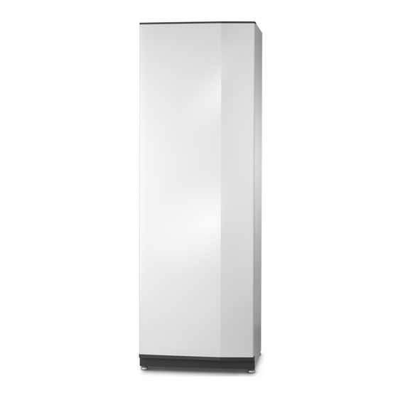
Summary of Contents for Nibe VPB S200
- Page 1 User and Installer Manual Water heater / Accumulator tank NIBE VPB S200, S300 CHB EN 2411-3 531224...
-
Page 3: Table Of Contents
2 For the User Maintenance 3 For the Installer Delivery and handling The water heater design Pipe connections Electrical installation Commissioning and adjusting 4 Technical data Dimensions Technical specifications Energy labelling Contact information NIBE VPB S200, S300 Table of Contents... -
Page 4: Important Information
General stand the hazards involved. Children shall NIBE VPB S is designed and manufactured according sound not play with the appliance. Cleaning and engineering practice in order to ensure safe usage. -
Page 5: Compatible Products
Heat pump (page 11) Shut off valves Hot water (page 12) Mixing valve Cold water (page 12) Shut-off valve Non-return valve Safety valve Electricity (page 13) Sensors Electrical anode (NIBE VPB S enamel only) NIBE VPB S200, S300 Chapter 1 | Important information... -
Page 6: For The User
Servicing should only be carried out by persons with the TIP! necessary expertise. The safety valve is not delivered with NIBE VPB S. When replacing components on NIBE VPB S only replacement Contact your installer if you are unsure how to parts from NIBE may be used. -
Page 7: For The Installer
NIBE VPB S should be transported and stored vertically in upwards to remove it from the frame. a dry place. However, the NIBE VPB S can be carefully laid on its back when being moved into the building. - 40 mm ASSEMBLY •... - Page 8 4. Assembly takes place in the reverse order. Remove side panel The side panels can be removed to facilitate the installation. Remove the screws from the upper and lower edges. Twist the panel slightly outwards. Chapter 3 | For the Installer NIBE VPB S200, S300...
-
Page 9: The Water Heater Design
ELECTRICAL COMPONENTS Hot water connection Direct-current anode (NIBE VPB S enamel only) Connection, hot water circulation Cable to direct-current anode (NIBE VPB S enamel only) Docking connection, supply line (from heat pump) Docking connection, return line (to heat pump) MISCELLANEOUS 1 Applies only to enamel and stainless steel. -
Page 10: Pipe Connections
The overflow pipe must be at least the same size as the safety valve. The overflow pipe must be Heat pump visible and its mouth must be open and not placed close to electrical components. Heating system Chapter 3 | For the Installer NIBE VPB S200, S300... - Page 11 This is the outline diagram. Actual installations must be planned according to applicable stand- ards. NIBE VPB S is a series of water heaters that are suitable for connection to e.g. a heat pump. Connection Further information about the system principle is available XL3 Cold water Ø...
- Page 12 The circulating water must have a temperature that prevents bacterial growth and scalding, and national standards must be met. The HWC return is connected to the HWC connection (XL5). -QZ1 -QZ1-FQ3 -QZ1-RN1 -QZ1-RM1 -QZ1-GP11 Chapter 3 | For the Installer NIBE VPB S200, S300...
-
Page 13: Electrical Installation
Disconnect the current using the cir- cuit breaker before carrying out any servicing. DIRECT-CURRENT ANODE NIBE VPB S Enamel is equipped with direct-current anode and enclosed with potentiostat from the factory. The anode cable (W1) is installed in the anode from the factory and only needs to be connected to the potentiostat. -
Page 14: Commissioning And Adjusting
Vent the coil via the vent valve (QM22) and the rest of the climate system via the relevant vent valves. Keep topping up and venting until all air has been re- moved and the pressure is correct. The figure shows VPB S200. 0,05 0,15 0,2 0,25 0,3 0,35 0,4 0,45 0,5... -
Page 15: Technical Data
Technical data Dimensions VPB S200 VPB S300 NIBE VPB S200, S300 Chapter 4 | Technical data... -
Page 16: Technical Specifications
VPB S300 Cu/E/R VPBS S300 Cu/E Efficiency class Heat loss Volume 178 / 178 / 176 278 / 274 / 282 277 / 270 Scale for the product’s efficiency class A+ to F. Chapter 4 | Technical data NIBE VPB S200, S300... -
Page 19: Contact Information
Tel: +48 (0)85 66 28 490 Hannabadsvägen 5, 285 21 Markaryd Tel. +41 (0)58 252 21 00 biawar.com.pl Tel: +46 (0)433-27 30 00 info@nibe.ch info@nibe.se nibe.ch nibe.se For countries not mentioned in this list, contact NIBE Sweden or check nibe.eu for more information. - Page 20 WS release date: 2024-03-12 15:02 Publish date: 2024-04-25 11:12 This is a publication from NIBE Energy Systems. All product illustrations, facts and data are based on the available information at the time of the publication’s approval. NIBE Energy Systems makes reservations for any factual or printing errors in this publication.


Need help?
Do you have a question about the VPB S200 and is the answer not in the manual?
Questions and answers