Table of Contents
Advertisement
Quick Links
Advertisement
Table of Contents

Subscribe to Our Youtube Channel
Related Manuals for Nibe VPB 200N


Summary of Contents for Nibe VPB 200N
- Page 1 Installer manual VPB 200N Hot water heater IHB GB 1046-3 031453...
-
Page 3: Table Of Contents
7 Service and maintenance Maintenance 4 Pipe connections Service actions General 8 Technical data Dimensions and pipe connections Heat pump Dimensions and setting-out coordinates Cold and hot water Technical specifications Installation alternative Item register 5 Electrical installation VPB 200N Table of Contents |... -
Page 4: Important Information
Marking VPB 200N is CE marked and fulfils IP21. The CE marking means that NIBE ensures that the product meets all regulations that are placed on it based on relev- ant EU directives. The CE mark is obligatory for most products sold in the EU, regardless where they are made. - Page 5 Scheme. Visit www.centralheating.co.uk for information. Warranty information Thank you for installing a new NIBE heat pump in your home. NIBE heat pumps are manufactured in Sweden to the very highest standard so we are pleased to offer our customers a comprehensive guarantee.
- Page 6 Chapter 1 | Important information VPB 200N...
- Page 7 Shut off valves Expansion vessel T&P valve Tundish Cold water (page 11) Shut off valves Non-return valve Mixing valve Safety valve Tundish Electricity (page 13) Hot water sensor Temperature limiter Miscellaneous Benchmark checklist VPB 200N Chapter 1 | Important information...
-
Page 8: Delivery And Handling
Assembly VPB 200N should be transported and stored vertically in The water heater is only designed for upright installa- a dry place. The VPB 200N may, however, be carefully tion. laid on its back when being moved into a building. -
Page 9: Supplied Components
Pressure reduction valve 2 x tundish Armoured hose Connector with cable (expansion vessel) Shut off valve Expansion vessel with holder Location The kit of supplied items is placed on top of the product. VPB 200N Chapter 2 | Delivery and handling... -
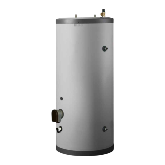
Page 10: The Water Heater Design
3 The water heater design Chapter 3 | The water heater design VPB 200N... - Page 11 IEC 81346-1 and 81346-2. HVAC components T&P valve Drain valve, hot water G ½" Inspection cover, hole Ø80. Submerged tube for hot water sensor (display) Submerged tube for hot water sensor (control) VPB 200N Chapter 3 | The water heater design...
-
Page 12: Pipe Connections
3. Close the valves and check the stainer. When the water heater and the climate system have been filled with water, VPB 200N must operate at maximum normal temperature for at least one hour. Thereafter the system must be drained of water and refilled. -
Page 13: Dimensions And Pipe Connections
Connecting cold and hot water There must be a mixing valve if the temperature can ex- ceed 60 °C. The flexible hose to the expansion vessel can be installed in the plugged connection on the safety valve. VPB 200N Chapter 4 | Pipe connections... -
Page 14: Installation Alternative
Connecting hot water circulation Installation alternative VPB 200N has a connection that allows hot water circu- VPB 200N can be connected in several different ways, lation. one of which is shown here. To reduce the risk of bacterial growth in systems with Further option information is available at www.nibe.co.uk... -
Page 15: Electrical Installation
Sensors VPB 200N can be supplemented with up to two hot water sensors, one for display and one for control. The display sensor is positioned in the submerged tube for the display sensor (UA1) and the control sensor in the submerged tube for control sensor (UA2). -
Page 16: Commissioning And Adjusting
4. Close the filling valve when the correct pressure is obtained. Venting 1. Vent the climate system via the relevant venting valves. 2. Keep topping up and venting until all air has been removed and the pressure is correct. Chapter 6 | Commissioning and adjusting VPB 200N... - Page 17 Adjustment is made when the flow temperature is approx. 45 ºC and at stable operation, 5 minutes after start-up or 5 minutes after defrost. Adjusting the charge flow for VPB 200N Δ T (°C) 18,0 17,0...
-
Page 18: Service And Maintenance
3. Close the valve by releasing it. If it does not close automatically when released, turn it anti-clockwise slightly. NOTE Do not remove or adjust any components that are part of this pressurised water heater. Contact your installer! Chapter 7 | Service and maintenance VPB 200N... -
Page 19: Technical Data
8 Technical data Dimensions and setting-out coordinates Ø570 VPB 200N Chapter 8 | Technical data... -
Page 20: Technical Specifications
Expansion relief valve, setting bar/MPa 6/0.6 Max operating pressure, T&P-valve bar/MPa 7/0.7 Max operating temperature, T&P-valve °C Max recommended heat pump size Total input power Discharge capacity, T&P valve Part No. 087 730 Chapter 8 | Technical data VPB 200N... -
Page 21: Item Register
Inspection of the installation, 5 Temperature limiter, 13 Installation alternative, 12 The water heater design, 8 To ground source heat pump, 12 List of components, 9 Installation area, 6 Transport, 6 Warranty information, 3 VPB 200N Chapter 9 | Item register... - Page 22 MAINS PRESSURE HOT WATER STORAGE SYSTEM COMMISSIONING CHECKLIST This Commissioning Checklist is to be completed in full by the competent person who commissioned the storage system as a means of demonstrating compliance with the appropriate Building Regulations and then handed to the customer to keep for future reference. Failure to install and commission this equipment to the manufacturer’s instructions may invalidate the warranty but does not affect statutory rights.
- Page 23 SERVICE RECORD It is recommended that your hot water system is serviced regularly and that the appropriate Service Record is completed. Service Provider Before completing the appropriate Service Record below, please ensure you have carried out the service as described in the manufacturer’s instructions.
- Page 28 NIBE Energy Systems Ltd 3C Broom Business Park Bridge Way Chesterfield S41 9QG Phone 0845 095 1200 Fax 0845 095 1201 info@nibe.co.uk www.nibe.co.uk...
Need help?
Do you have a question about the VPB 200N and is the answer not in the manual?
Questions and answers