
Related Manuals for Atlas Copco HiLight V4 W WUX


Summary of Contents for Atlas Copco HiLight V4 W WUX
- Page 1 Instruction Manual Instruction Manual For Portable Light Tower Generator English Engine Kubota D1105 HiLight V4 W WUX...
- Page 3 Instruction Manual for Portable Light Tower Generator HiLight V4 W WUX Original instructions Printed matter N° 9829 4075 00 ATLAS COPCO - PORTABLE ENERGY DIVISION www.atlascopco.com 02/2017...
- Page 4 Neglecting maintenance or making changes to the setup of the machine can result in major hazards, including fire risk. While every effort has been made to ensure that the information in this manual is correct, Atlas Copco does not assume responsibility for possible errors.
-
Page 5: Table Of Contents
Table of contents Preface Maintenance ..........20 Daily inspection .......... 20 Please read the following instructions carefully before starting to use your light tower. Lamp replacement........20 5.2.1 Servicing the engine ....... 20 Main parts - HiLight V4 W ......7 It is a solid, safe and reliable machine, built according to the latest technology. - Page 6 - 6 -...
-
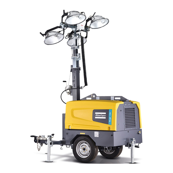
Page 7: Main Parts - Hilight V4 W
Main parts - HiLight V4 W "The light tower provides an undercarriage ( frame, axle and towbar ) and 4 floodlights of 1000 W each. The light tower is very useful for construction sites where neither electricity nor lighting is available." - 7 -... -
Page 8: Safety Information
Atlas Copco. Do not position light tower CAUTION under power lines. Crush hazard. -
Page 9: Engine Safety
Engine safety CAUTION DANGER Risk of severe burn. Operator safety Before handling lights, allow Asphyxiation hazard. lights to cool for 15 minutes. - Operate the engine outdoors DANGER and keep away from engine exhaust. Explosion hazard. - Keep engine, fuel, and other - If operating in an enclosed area, vent exhaust fumes to combustibles away from... -
Page 10: Service Safety
- Do not remove radiator cap labels. (Replacement labels are available from the when engine hot. High voltage. Atlas Copco.) Contents are hot and under Contact with live electrical ∞ When hoisting or loading the trailer: pressure. circuits will cause severe injury or death. -
Page 11: Assembly
For combo hitch option only: • B - Lifting jack When the light tower ships from the Atlas copco, the bar is set up to use the lunette ring for towing by a vehicle with a pintle hook. To use a ball coupler, follow the procedure below. -
Page 12: Light Fixture Wiring
Light fixture wiring - 12 -... -
Page 13: Operation
Operation Safety a Verify the light tower mast is in the down position (see Figure 3.2). To lower the tower, see page 17. Before operating the light tower, read and be familiar b If necessary, attach a red flag to the top of the with this instruction manual. -
Page 14: During Towing
Hoisting Location Verify approved safety chains are attached properly to both the trailer and tow vehicle. The light tower may be hoisted by means of the hoist • To achieve the best possible light coverage, locate ring mounted on the lifting beam (see Figure 3.2). the light tower on the same level as the area to be During towing lighted, or higher. -
Page 15: Deployment
Deployment the locking pin snaps into position with an audible e Take the weather into account: do not raise or use “click.” the tower in high winds or an electrical storm. The tower can afford 80 km/h wind load. 7. Pull the jack locking pin and rotate the jack Levelling the trailer downward until the locking pin engages. - Page 16 2. To raise the tower, see Figure 3.5 and follow these instructions: a Rotate the handle of the mast-mounted winch to tighten the cable until the lights are at the desired height. b To rotate the mast, loosen the rotation-lock knob and use the handle on the mast to rotate the mast either left or right.
-
Page 17: Lowering The Tower
Lowering the tower Before moving or storing the light tower, lower the mast and lock it in place. To lower the tower, see Figure 3.6 and use the following instructions. 1. Turn off the tower lights and the engine. For increased lamp life, allow the lights to cool for 15 minutes before proceeding. -
Page 18: Engine Operation
Engine operation • Crank the engine immediately after the indicator light goes out. CAUTION Starting the engine 3. When the glow-plug indicator light goes out, turn and hold the key at the START position. The engine can overheat and damage the 1. -
Page 19: Lights
Stopping the engine • After the lamps are turned off, they will not turn Degraded lamps on again until they are cool. The lamps can take up To stop the engine: Degraded lamps may be difficult to light, and may to 15 minutes to cool. -
Page 20: Maintenance
Maintenance Daily inspection Lamp replacement c Remove the screws securing the flange rings and remove the flange rings. When the light tower is in regular use, the following To replace a light bulb (lamp), refer to Figure 4.1 and d Remove the protective lamp cover with the gasket items should be checked daily: follow the instructions below. -
Page 21: Wiring Diagrams
Wiring diagrams DANGER High voltage. Contact with live electrical circuits will cause severe injury or death. • Turn off power before servicing any component on the light tower. • Only a qualified electrician should service the light tower electrical system. - 21 -... -
Page 22: Maintenance Schedule
3002 6087 50 for the most important sub-assemblies, Atlas Copco has developed service kits that combine all wear parts. These service kits offer you the benefits of genuine parts, save on administration costs and are offered at reduces price, compared to the loose components. Refer to the parts list for more information on the contents of the service kit. - Page 23 Check rubber flexibles Check emergency stop Clean radiator Replace air filter element Check/Replace safety cartridge Inspection by Atlas Copco service technician Inspect starter motor Inspect waterpump Inspect alternator Check engine protective devices Check valve in the fuel return line (for mechanical injection system)
- Page 24 Figure 4.4 Comprehensive wiring schematic - 9829 3800 74 - 24 -...
- Page 25 Figure 4.5 Generator-capacitor excitation schematic Reference Description Rotor Stator Excitation coils Capacitor Generator/terminal block Control box lights Wire Colours Black Brown Clear Green Grey Blue Light Blue Orange Pink Purple Shield Violet White Yellow - 25 -...
- Page 26 Figure 4.6 Trailer wiring - 1094 2932 00 Wire Colours Reference Description Green Right stop and turn lights Right stop, turn, and tail lights Yellow Left stop and turn lights Left stop, turn, and tail lights Brown License plate, tail, and side Side light, amber lights Side light, red...
- Page 27 Figure 4.6 - 9829380078 - 27 -...
-
Page 28: Dimension Drawing - 9829 3900 86
Dimension Drawing - 9829 3900 86 Lifting eye(Ø50) Cooling Air Cooling Air Outlet Inlet Frame Drain 1887 [74,291] 990,4 [38,994] 3093 [121,772] - 28 -... - Page 29 1577,5 [62,107] Service Door For cleaning cooler Emergency Stop Exhaust Air outlet R686 [27,015] R686 [27,006] 700 [27,559] 920 [36,220] 1349 [53,111] 342,5 [13,484] 342,5 [13,484] - 29 -...
-
Page 30: D900 Axle With Leaf Springs Use And Maintenance Manual
D900 axle with leaf springs use and maintenance manual Axle Maintenance • check the quality and quantity of grease, if necessary, the filling or replacement of grease. 10,000 km or 3 years later: Wheel Bearing Grease: 2 # of lithium grease. •... -
Page 31: Setting The Lc1003™ Controller
Setting the Lc1003™ controller DOWN: Is used for navigating the Controller settings should only be instrumentation, event log and performed by a qualified technician. STOP: Is used to activate Stop/Reset configuration screens and to go to the mode. When pressing the STOP next parameter level. -
Page 32: Module Display
Module display Icon overview Display Description Instrumentation icons Appears when the event log is Home page being displayed Display Description The home page is the page displayed when no other The default home page which Current time held in the unit page has been selected: displays Generator voltage and the Auto Run icon... - Page 33 Front panel editor (FPE) / Auto Run icons Navigation menu Display Description To enter the navigation menu, press both the UP and Appears when the unit is in the Display Description DOWN buttons simultaneously. front panel editor. To navigate to the desired page, select the Appears when a remote start input corresponding icon by pressing the UP and DOWN is active...
- Page 34 To view the event log: Display Description 1. Press the UP and DOWN buttons simultaneously Event Log to display the navigation menu. 2. Once entered, cycle to the event log section (1) and enter. Event log 3. To view the event log, repeatedly press the UP or The Lc1003™...
- Page 35 Menu flow Configuration Parameters – Scheduler Enable Scheduler On (1), Off (0) Schedule Run On or Off On (1), Load Off (0) Schedule Period Weekly (0), Monthly (1) Scheduler (1) 0:00:00 Start Time Scheduler (1) Start Day (1=Monday) Scheduler (1) 1,2,3,4 Start Week Scheduler (1) Duration...
- Page 36 Setting the Lc1003™ clock Setting the Lc1003™ timer 907 Scheduler duration Set the desired time period. When this value is set, 1. Enter the weekly timer menu by pressing the 1. Enter the weekly timer menu as described above. Event 1 is closed. STOP and AUTO button simultaneously.
- Page 37 Setting the sensitivity regulator There are 2 blinking levels: The photocell sensitivity regulator is used for – Level 1: slow blinking regulating the luminosity sensitivity level of the The photocell detects there is enough light, photocell. according to its set sensitivity level. When the red LED (1) on the regulator is blinking, the –...
- Page 38 - 38 -...
Need help?
Do you have a question about the HiLight V4 W WUX and is the answer not in the manual?
Questions and answers