Table of Contents
Advertisement
Advertisement
Table of Contents
Troubleshooting

Related Manuals for Atlas Copco QAS 14


Summary of Contents for Atlas Copco QAS 14
- Page 1 Instruction Manual for AC Generators English QAS 14-20 Kd...
- Page 3 QAS 14-20 Kd Instruction Manual for AC Generators Instruction manual ..................5 Circuit diagrams ..................81 Original instructions Printed matter N° 2954 3380 04 ATLAS COPCO - PORTABLE AIR DIVISION www.atlascopco.com 11/2010...
- Page 4 While every effort has been made to ensure that the information in this manual is correct, Atlas Copco does not assume responsibility for possible errors. Copyright 2010, Atlas Copco Airpower n.v., Antwerp, Belgium. Any unauthorized use or copying of the contents or any part thereof is prohibited.
-
Page 5: Table Of Contents
While every effort has been made to ensure that the information in this manual is correct, Atlas Copco does not assume responsibility for possible errors. Atlas Copco reserves the right to make changes without prior notice. -
Page 6: Generators
The policy of Atlas Copco is to provide the users of their Atlas Copco equipment. It is the responsibility of unsafe operating conditions. Take necessary steps to equipment with safe, reliable and efficient products. -
Page 7: General Safety Precautions
The manufacturer does not accept any liability for any Normal ratings (pressures, temperatures, speeds, 14 When working on the unit, wear safety clothing. damage arising from the use of non-original parts and for etc.) shall be durably marked. Depending on the kind of activities these are: safety modifications, additions or conversions made without glasses, ear protection, safety helmet (including Operate the unit only for the intended purpose and... - Page 8 - check the towbar, the brake system and the Atlas Copco. towing eye. Also check the coupling of the To lift heavy parts, a hoist of ample capacity, tested...
- Page 9 Never refill fuel while the unit is running, unless occasional visitors staying a limited time only, otherwise stated in the Atlas Copco Instruction apply compressed air or inert gas to your skin or - above 85 dB(A): room to be classified as a noise- Book (AIB).
- Page 10 Replace the damaged wires or correct the dangerous invisible particles will almost certainly be present Parts shall only be replaced by genuine Atlas Copco condition before restarting. Make sure that all too; but the fact that no dust can be seen is not a replacement parts.
- Page 11 18 Maintenance and repair work should be recorded in in or on the machine. Never leave rags or loose or approved by Atlas Copco or the machine an operator’s logbook for all machinery. Frequency clothing near the engine air intake.
- Page 12 When connecting an auxiliary battery (AB) in Tool applications safety parallel to the unit battery (CB) with booster cables: Apply the proper tool for each job. With the knowledge connect the + pole of AB to the + pole of CB, then of correct tool use and knowing the limitations of tools, connect the - pole of CB to the mass of the unit.
-
Page 13: Leading Particulars
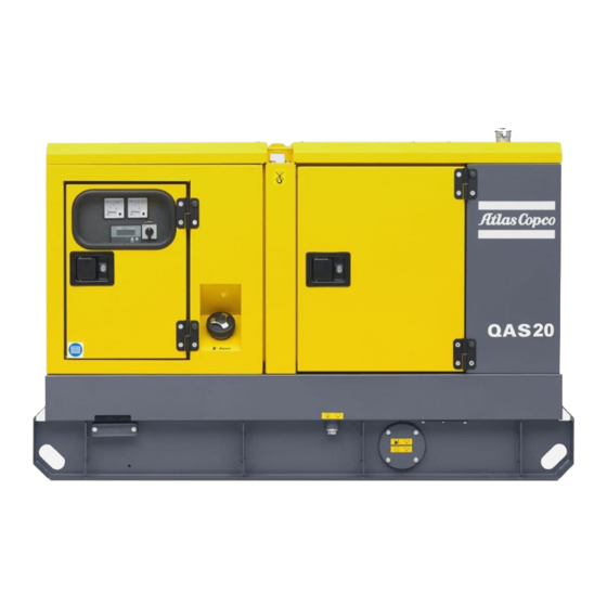
General description The QAS 14 and QAS 20 are AC generators, built for continuous running at sites where no electricity is available or as stand-by in cases of interruption of the mains. The generator operates at 50/60 Hz, 230/240 V in line-to-neutral mode and 400/480 V in line-to-line mode. The QAS 14 and QAS 20 generators are driven by a fluid-cooled diesel engine, manufactured by KUBOTA. - Page 14 Alternator Air filter Battery switch Coupling Drain flexible engine oil Drain flexible coolant Drain and access hole (in the frame) Drain plug fuel Engine Filler cap fuel Filler cap engine oil Filler cap coolant Fuel filter Battery Oil filter Engine oil level dipstick Vacuum indicator - 14 -...
-
Page 15: Bodywork
Closed Position 2 The earthing rod, connected to the generator’s earth terminal is located at the side of the frame. QAS 14 Kd, QAS 20 Kd Indicates the partnumbers of Indicates the drain plug for the engine Markings the different service packs fuel. -
Page 16: Drain Plugs And Filler Caps
H0 ..Panel light Drain plugs and filler caps Control and indicator panel Qc1002™ The drain holes for the engine oil, the coolant and the S20..ON/OFF/REMOTE switch plug for the fuel, are located and labelled on the To start up the unit (locally or remote). General description Qc1002™... - Page 17 Pushbutton and LED functions Following LEDs are used on the Qc1002™ Menu Overview Qc1002™ At Qc1002™, the LCD will show following Following pushbuttons are used on information: the Qc1002™ – in Normal condition (scroll through the information using UP and DOWN): Power Qc 1002 •...
- Page 18 Controller type and version display LOG list display Battery Voltage display Qc1002 LOG List Battery 13.2 V v1.00.0 00168.1h This view shows the controller type and the ASW This view shows the alarm memory and gives access This view shows the Battery voltage and the running version number.
- Page 19 – Generator Overvoltage: failclass, enable, delay, These special statuses are: setpoint – Unit Type It's possible to scroll between configuration menu's by using the pushbuttons UP and DOWN. Unit type 1 for QAS 14-20 ! PREHEAT Pushing ENTER button activates –...
- Page 20 This is the described menu flow for changing the unit type: Qc1002 Qc 1002 Parameter Running time Unit type Unit type - 20 -...
- Page 21 Alarm Display (pop-up window) Following general groups of Alarms exist: – Warning: Alarm LED lights up + Alarm pop-up GENERATOR appears on the display + Alarm relay is OVERVOLTAGE empowered (if configured) – Trip of GB: ‘Warning’ actions + Generator Contactor opens GENERATOR –...
- Page 22 LOG list Remote start operation The unit will keep an event log of the latest 30 events. Installation wirings: ENGINE ALARM Events are: – X25.1 & X25.2 to be wired for the remote start switch. – shutdowns – X25.3 & X25.4 to be wired for the remote –...
-
Page 23: Control And Indicator Panel Qc2002
Pushbutton and LED functions S20 ..ON/OFF switch Control and indicator panel Position O: No voltage is applied to the Qc2002™ Following pushbuttons are used on Qc2002™ module, the generator will not the Qc2002™ General description Qc2002™ control start. panel Position I: Voltage is applied to the Qc2002™... - Page 24 Following LEDs are used on the Mains Green LED indicates that it is Qc2002™ contactor possible to close the Mains START: Is used to start the unit in Contactor (only in AMF mode), if Manual Operation. the Generator contactor is open. Power Alarm Flashing red LED indicates that an...
- Page 25 Qc2002™ Menu Overview Parameter display – in Alarm condition (scroll through DOWN information using At Qc2002™, the LCD will show following • a list of all active Alarms information: Parameter It's possible to scroll through the views, using the UP –...
- Page 26 LOG list display Battery voltage display Power factor - frequency generator - frequency mains display Battery 13.2 V LOG List 0.00 00168.1h G f L1 50Hz M f L1 50Hz This view shows the Battery voltage and the running This view shows the alarm memory and gives access hours.
- Page 27 Active - reactive - apparent power Line voltages mains display Qc2002™ Menu Description display Status Display (pop-up window) M L1-L2 400V M L2-L3 400V 80kW M L3-L1 400V 0kVAr 80kVA This view shows the line voltages of the mains (is only shown in AMF mode).
- Page 28 Island operation Automatic Mains Failure (AMF) operation If a special status has elapsed, the active view will be entered again automatically. – This operation type is selected for local/remote – This application is only possible in combination If an Alarm comes up, the Alarm Display is shown. start applications, without the Mains (= stand- with the Auto mode.
- Page 29 Running hours adjust Unit menu MF high frequency Running Time Unit MF high freq Cur. 20000 C/bar C/bar F/psi 100% 120% This menu is used to adjust the amount of running This menu is used to select the units into which This menu is used to set the maximum limit for the hours.
- Page 30 M frequency delay MF high voltage M voltage delay M freq delay M volt delay MF high volt 9900s 9900s 100% 120% This menu is used to set the delay, which defines how This menu is used to set the maximum limit for the This menu is used to set the delay,, which defines how long the mains frequency has to be back within the mains voltage, in % of the nominal voltage (in AMF-...
- Page 31 Overvoltage enable Overvoltage setpoint Undervoltage delay > Volt enable > Volt < Volt Delay Enable enable disable Overvoltage failclass Undervoltage enable Undervoltage setpoint > Volt < Volt enable < Volt warning warning shutdown Enable enable disable Overvoltage delay Undervoltage failclass Overfrequency enable >...
- Page 32 Alarm Display (pop-up window) Overfrequency delay Underfrequency delay > Freq Delay < Freq Delay Overfrequency setpoint Underfrequency setpoint In case an Alarm occurs, a pop-up window will automatically be displayed for as long as the alarm is active, no matter which view is active. The flashing >...
- Page 33 Following general groups of Alarms exist: – Warning: Alarm LED lights up + Alarm pop-up GENERATOR ENGINE ALARM appears on the display + Alarm relay is OVERVOLTAGE empowered (if configured) – Trip of GB: ‘Warning’ actions + Generator Contactor opens GENERATOR –...
-
Page 34: Output Terminal Board
Fail classes Output terminal board All the activated alarms of the Qc2002™ have their The output terminal board option is situated below the own pre-defined fail class. control and indicator panel. TEMPERATURE All alarms are enabled according to one of these three statuses: –... -
Page 35: Spillage Free
(30 mA) or the is labelled IN. forklift. overcurrent protection (QAS 14: 20 A, Position O: No de-energising of the main It avoids accidental spilling of engine fluids. QAS 20: 32 A) is activated or when the circuit breaker Q1 when an earth fault shunt trip is energized. -
Page 36: Operating Instructions
IEC 364-3, i.e. one point in – Leave enough space for operation, inspection and Consult Atlas Copco for measures against the adverse the power source directly earthed - maintenance (at least 1 meter at each side). - Page 37 Quality, minimum section and Protection The lowest acceptable wire section and the maximum length of cables corresponding maximum cable or conductor length For safety reasons, it is necessary to for multiple core cable or H07 RN-F, at rated current The cable connected to the terminal board of the provide an isolating switch or circuit (20 A), for a voltage drop e lower than 5% and at a generator must be selected in accordance with local...
-
Page 38: Before Starting
During operation Qc1002™ Before starting Operating Qc1002™ Following points should be carried out regularly: – With the generator standing level, check the Starting Qc1002™ engine oil level and top up if necessary. The oil – Check the engine gauges and the lamps for normal level must be near to, but not exceed the high mark readings. -
Page 39: Operating Qc2002
Stopping Qc1002™ To start up the unit from a remote Operating Qc2002™ location, proceed as follows: To stop the unit locally, proceed as Starting Qc2002™ – Put the starter switch S20 in position I (ON). follows: Voltage is applied to the Qc2002™ module. To start up the unit locally, proceed –... - Page 40 During operation Qc2002™ Stopping Qc2002™ – Cooldown period default 15 sec. – Put the starter switch S20 in position O (OFF) to Following points should be carried out regularly: To stop the unit , proceed as follows: shut down the voltage apply towards the –...
-
Page 41: Maintenance
2912 6383 06 For the most important subassemblies, Atlas Copco has developed service kits that combine all wear parts. These service kits offer you the benefits of genuine parts, save on administration costs and are offered at reduced price, compared to the loose components. Refer to the parts list for more information on the contents of the service kits. - Page 42 Generators in standby application have to be tested on a regular basis. At least once a month the engine should run Inspection by Atlas Copco Service technician for minimum 30 minutes at a high load (50% - 70%) that the engine reaches its operating temperature.
-
Page 43: Engine Maintenance
If the N-terminal is connected to the earthing system, clearence. When changing from mineral to it must be disconnected from the earth terminal. (Rocker cover gasket: QAS 14 - 2913 3074 00 & synthetic oil (or the other way Disconnect the AVR. QAS 20 - 2913 3075 00). -
Page 44: Engine Oil Level Check
Engine oil level check EURO -3 & -2, EPA TIER II & III engines running on PAROIL from Atlas Copco is the ONLY oil tested Consult the Engine Operation Manual for the oil low sulphur diesel for lower oil and fuel consumption. -
Page 45: Engine Coolant Specifications
PARCOOL EG is the only coolant that has been Never remove the cooling system filler number tested and approved by all engine manufacturers cap while coolant is hot. currently in use in Atlas Copco compressors and 0.175 1604 5308 00 The system may be under pressure. generators. -
Page 46: Coolant Check
Flush high engine operating temperatures. parameters. – Flush twice with clean water. Used coolant must – A refractometer can be ordered from Atlas Copco Visual check be disposed or recycled in accordance with laws with part number 2913 0028 00. -
Page 47: Storage Of The Generator
Storage of the generator Preparing for operation after storage Storage Before operating the generator again, remove the – Store the generator in a dry, frost-free room which wrapping, VCI paper and silica gel bags and check the is well ventilated. generator thoroughly (go through the checklist “Before starting”... -
Page 48: Checks And Trouble Shooting
Checks and trouble shooting Checking voltmeter P4 – Put a voltmeter in parallel with voltmeter P4 on Never perform a test run with the control panel. connected power cables. Never touch – Check that the read-out of both voltmeters is the an electrical connector without a same. -
Page 49: Alternator Troubleshooting
Alternator troubleshooting Symptom Possible cause Corrective action Alternator gives 0 Volt Blown fuse. Replace fuse. Excite the alternator by applying a 12V battery voltage with a 30 No residual voltage. resistor in series on the + and - terminals of the electronic regulator, respecting the polarities. -
Page 50: Engine Trouble Shooting
Engine trouble shooting Not enough power The pressure of the lubricating oil is The table below gives an overview of the possible engine problems and their possible causes. too low – Restriction in a fuel pipe. – Wrong grade of lubricating oil. –... - Page 51 Black exhaust smoke The engine runs erratically The pressure of the lubricating oil is too high – Restriction in air filter/cleaner or induction – Fault in fuel control. system. – Wrong grade of lubricating oil. – Restriction in a fuel pipe. –...
-
Page 52: Qas 20 Units
– Automatic battery charger – Air in fuel system. The engine control circuit diagrams and the power – Battery switch circuit diagrams for the standard QAS 14 and QAS 20 – Engine coolant heater The engine shuts down after approx. units: –... -
Page 53: Description Of The Electrical Options
Outlet sockets (S) - 3-phase To use the batery charger: Description of the electrical – Provide the X25 connector, located at the side of options A brief description of all outlet sockets and circuit the power cubicle, with external power to use the breakers provided on the generator is given hereafter: Automatic battery charger battery charger. - Page 54 Outlet sockets (S) for Single phase option A brief description of all outlet sockets and circuit breakers provided on the generator is given hereafter: X2 ..1-phase outlet socket (230 V AC) Qc 1002 Qc 1002 Provides phase L, neutral and earthing. X3 ..
- Page 55 Changing the output frequency is when a short-circuit occurs at the load side protection (QAS 14: 50 Hz-32 A, 60 Hz- only allowed after shutdown. or when the overcurrent protection (QAS 14: 40 A, QAS 20: 50 Hz-50 A, 60 Hz-63 A) is...
- Page 56 1 phase low output voltage. 1 phase - 3 phase protection (QAS 14: 40 A, QAS 20: 63 A) is Selector switch S10 is located on the activated. It must be reset manually after The generator can run in two different modes: alternator.
- Page 57 When using this selection, the generator provides a voltage or a 3 phase low output voltage. protection (QAS 14: 32 A, QAS 20: 50 A) is 230 V output voltage. (IT = active) Selector switch S10 is located on the activated.
- Page 58 IT-relay X1 ..Main power supply (400 V AC) Terminals L1, L2, L3, N (= neutral) and PE Not available for the Box A (= earthing), hidden behind the control panel Compact 60 Hz units. door and behind a small transparent door. The generator is wired for an IT network i.e.
- Page 59 (1) of the Cosmos module will light up when the circuit breaker. installation has been carried out correctly. For information about COSMOS™, consult your local Atlas Copco dealer. - 59 -...
-
Page 60: Overview Of The Mechanical Options
The following mechanical options are available for entering the fuel system. the QAS 14 and QAS 20 units: – External fuel tank connection (with/without quick Position 1: Indicates that the fuel... - Page 61 Undercarriage (axle, towbar, towing To maintain the undercarriage Wheel chocks eyes) – Check the tightness of the towbar bolts, the axle The option wheel chocks allows to park the generator bolts and the wheel nuts at least twice a year and on sloping ground.
-
Page 62: General Description
Lighting tower General description The lighting tower option provides an undercarriage (frame, axle and towbar) and 6 halogen projectors of 1500 W each. There are two versions of undercarriages available: on-road (with road signalisation) and off-road (without road signalisation). The lighting tower is very useful for construction sites where no electricity nor lighting is available. -
Page 63: Operating Procedure
Operating procedure Erection of the lighting tower General guidelines 1. Positioning of the generator mounted on the light- ing tower. 1. Check the terrain where the lighting tower has to • Locate the rear-end of the generator upwind, be erected: (see figure below), away from contaminated •... - Page 64 3. Erect the mast of the lighting tower: 4. Turning the mast of the lighting tower. The mast of the lighting tower can be turned to the • Loosen the elevation cable (EC) by turning the left and to the right to locked positions on 45°, lever of the winding mechanism (WM) 90°, 135°...
- Page 65 Lighting tower maintenance Starting the generator and switching Taking down the lighting tower the lights on and off – Refer to the maintenance instructions mentioned Do not take down the lighting tower in the chapter dealing with the “Undercarriage” Only start the generator and switch with ligths switched...
-
Page 66: Technical Specifications
Technical specifications Technical specifications for QAS 14 units Readings on gauges Gauge Reading Unit Ammeter L3 (P3) Below max. rating Voltmeter (P4) Below max. rating Settings of switches Switch Function Activates at Engine oil pressure Shut down 0.5 bar Engine coolant temperature Shut down 103°C... - Page 67 Performance data 2) 3) 5) Rated active power (PRP) 3ph 10.9 kW 13.0 kW Rated active power (PRP) 1ph (optional) 10.0 kW 12.7 kW 0.8 cos 0.8 cos Rated power factor (lagging) 3ph 1.0 cos 1.0 cos Rated power factor (lagging) 1ph (optional) Rated PRP power 3ph 13.7 kVA...
- Page 68 Operation single single Start-up and control mode manual/automatic manual/automatic Start-up time unspecified unspecified Mobility/Config. acc. to ISO 8528-1:1993 transportable/D transportable/D (optional) mobile/E mobile/E Mounting fully resilient fully resilient Climatic exposure open air open air Status of neutral (ELR-config.) (optional) earthed earthed Status of neutral (IT-config.) (optional) insulated...
- Page 69 Electrical system 12 Vdc 12 Vdc Emission compliance EU STAGE II Power circuit Circuit-breaker, 3-ph. Number of poles Thermal release It (thermal release is higher at 25°C) 20 A 20 A Magnetic release Im 3..5xIn 3..5xIn Circuit-breaker, 3-ph., lower voltage (optional) Number of poles Thermal release It (thermal release is higher at 25°C) 32 A...
- Page 70 Notes Reference conditions for engine performance to ISO 3046-1. See derating diagram or consult the factory for other conditions. At reference conditions unless otherwise stated. Rating definition (ISO 8528-1): LTP: Limited Time Power is the maximum electrical power which a generating set is capable of delivering (at variable load), in the event of a utility power failure (for up to 500 hours per year of which a maximum of 300 hours is continuous running).
- Page 71 Derating Temperature Height (°C) 1000 1500 2000 2500 3000 3500 For use of generator outside these conditions, please contact Atlas Copco. - 71 -...
-
Page 72: Technical Specifications For Qas 20 Units
Technical specifications for QAS 20 units Readings on gauges Gauge Reading Unit Ammeter L3 (P3) Below max. rating Voltmeter (P4) Below max. rating Settings of switches Switch Function Activates at Engine oil pressure shut down 0.5 bar Engine coolant temperature shut down 105°C Specifications of the engine/alternator/unit... - Page 73 Rated PRP power 3ph 20.0 kVA 24.2 kVA Rated PRP power 1ph (optional) 13.3 kVA 16.7 kVA Rated voltage 3ph. line to line 400 V 480 V Rated voltage 3ph. line to line lower voltage (optional) 230 V 240 V Rated voltage 1ph (optional) 230 V 240 V...
- Page 74 (optional) mobile/E mobile/E Mounting fully resilient fully resilient Climatic exposure open air open air Degree of protection (cubicle) IP 54 IP 54 Status of neutral (ELR-config.) (optional) earthed earthed Status of neutral (IT-config.) (optional) insulated Alternator 4) Standard IEC34-1 IEC34-1 ISO 8528-3 ISO 8528-3 Make...
- Page 75 Power circuit Circuit-breaker, 3-ph. Number of poles Thermal release It (thermal release is higher at 25°C) 32 A 32 A Magnetic release Im 3..5xIn 3..5xIn Circuit-breaker, 3-ph., lower voltage (optional) Number of poles (optional) Thermal release It (thermal release is higher at 25°C) 50 A 63 A Magnetic release Im...
- Page 76 Notes Reference conditions for engine performance to ISO 3046-1. See derating diagram or consult the factory for other conditions. At reference conditions unless otherwise stated. Rating definition (ISO 8528-1): LTP: Limited Time Power is the maximum electrical power which a generating set is capable of delivering (at variable load), in the event of a utility power failure (for up to 500 hours per year of which a maximum of 300 hours is continuous running).
- Page 77 Derating Temperature Height (°C) 1000 1500 2000 2500 3000 3500 For use of generator outside these conditions, please contact Atlas Copco. - 77 -...
-
Page 78: Conversion List Of Si Units Into British Units
35.315 cfm cos phi " Nominal rated current Manuf. year/Baujahr/Année de fabrication 1 mbar 0.401 in wc MADE BY ATLAS COPCO AIRPOWER n.v. WILRIJK, BELGIUM Power factor 0.225 lbf Manufacturing year 1 Nm 0.738 lbf.ft 1615 6945 00 EEC mark in accordance witt Machine Directive 32 + (1.8 x t... -
Page 79: Disposal
Your Atlas Copco generator consists for the most part Remove the batteries. Do not throw batteries into the of metallic materials, that can be remelted in fire (explosion risk) or into the residual waste. - Page 80 - 80 -...
- Page 81 Circuit diagrams - 81 -...
- Page 82 9822 0992 65/00 Applicable for QAS 14-20 Compact - Power circuit See Note 2 400V/480V 240V-60Hz to Circ.Diagr ENGINE Ampere-meter F1-F3 Fuses 4 A Alternator to Circ.Diagr ENGINE Automatic voltage regulator Ampere-meter Earth leakage relay (O) IT-relay (O) Circuit breaker (O)
- Page 83 Outlet socket 32 A (O) Outlet socket 16 A (O) C D E Outlet socket 16 A (O) Terminal strip Optional equipment Coolant Heater 14-20 16A-1ph (Q1) 16A/30mA 30-40 16A-1ph (Q1) 16A/30mA Notes Note 1: The PE-N connection has to be made at the Wire Size x Wire Size y alternator-side of main Circuit Breaker Q1.
- Page 84 F1-F2 Fuses 4 A 9822 0992 66/00 Alternator Applicable for QAS 14-20 Compact - Power circuit - Single phase Automatic voltage regulator Earth leakage relay (O) IT-relay (O) Circuit breaker Circuit breaker 32 A (O) 230V 50Hz See Note 2...
- Page 85 Coolant Heater 30mA Wire Size x Wire Size y 230V-50Hz 60/5A 10mm 10mm 1ph - ZZ 60/5A 16mm 16mm Wire Size x Wire Size y 230V/240V 60/5A 10mm 10mm 1ph - ZZ 60/5A 16mm 16mm Legend Notes Wire size : Colour code : a = 1 mm 0 = black...
- Page 86 9822 0992 67/00 Applicable for QAS 14-20 Compact - Power circuit - Dual voltage, 50 Hz F1-F3 Fuses 4 A Voltage adjustment 1 k (O) Battery charger (O) Alternator Emergency stop Terminal board Automatic voltage regulator (S2a: see Engine circuit)
- Page 87 Twisted Pair Cubicle Alt. Cubicle X11.4 Alt. S10d X11.5 X11.2 X11.1 X11.3 S10b S10c X11.6 X11.7 Q1.1 Q1.2 U> U> Legend Wire size : Colour code : 0 = black aa = 0.5 mm 1 = brown a = 1 mm 2 = red b = 1.5mm 3 = orange...
- Page 88 9822 0992 73/01 Applicable for QAS 14-20 Compact - Power circuit - Dual voltage, 50 Hz, single phase X9.28 110V X9.29 X9.T12 X9.T9 X9.T4 (12) (11) (L1) (10) See Note 3 - 88 -...
- Page 89 See Note 1 31 34 Q1.1 Q1.2 Wire Size x Wire Size y Wire Size z 60/5A 2.5mm 10mm 10mm 60/5A 16mm 16mm 100/5A 100A 10mm 16mm 150/5A 125A 16mm 16mm Q1.1 Q1.2 Legend Wire size : Colour code : U>...
- Page 90 9822 0992 77/01 Applicable for QAS 14-20 Compact - Engine circuit 20 1 19 Legend Position of Relay Contacts Wire size : Colour code : a = 1 mm h = 25 mm 0 = black 6 = blue b = 1.5mm...
- Page 91 Fuel level sensor Speed sensor Preheat resistor Battery 12 Vdc Charging alternator Starter solenoid Preheat relay Starter motor Fuel feed pump Battery switch (O) Engine controller unit (O) High coolant temperature switch Low oil pressure switch Coolant temperature sensor Connector wire harness (see Controller circuit) Fuel solenoid Optional equipment...
- Page 92 9822 0992 78/01 Applicable for QAS 14-20 Compact - Controller circuit Qc1002™ Generator control unit (configure in unit type 1) Fuse 10 A DC Panel light a6 a2 a0 a0 a3 a3 a3 a3 Starter relay 26 27 P1-P3 Amperemeter...
- Page 93 to Circ.Diagr POWER X9.441 & X9.442 b6 b0 Sx=Remote Start/Stop-switch (*)= Connect L2 to X25.5 with 230Vd-systems MAINS SUPPLY (1P+N) Generator Contactor Customer's Installation Output: 12Vdc, max.8Adc1 S12b (see Instruction Manual) Note: with dedicated 60Hz-cubicles, DO NOT connect wire 12/a6 to X10.C4 Position of Relay Contacts Dual Frequency to Circ.Diagr POWER...
- Page 94 9822 0992 79/02 Applicable for QAS 14-20 Compact - Controller circuit Qc2002™ towards to Circ.Diagr POWER X25.8 X9.441 & X9.442 a6 a2 b6 b0 a0 a0 a0 a0 a0 26 27 37 38 53 54 57 58 Fx Fx Fx Fx...
- Page 95 E F G H I J K L M N a3 a3 to Circ.Diagr POWER X9.12 to A1.17 to Circ.Diagr POWER S12b X9.13 to Circ.Diagr POWER Dual Frequency X9.5 Legend Note: With dedicated 60Hz-cubicles, Position of Relay Contacts to A1.17 to A1.16 Wire size : Colour code :...
- Page 96 - 96 -...
- Page 97 Following documents are provided with this unit: – Test Certificate – EC Declaration of Conformity: EC DECLARATION OF CONFORMITY We, Atlas Copco Airpower n.v., declare under our sole responsibility, that the product Machine name : Power generator (< 400 kW) Commercial name : Serial number Which falls under the provisions of article 12.2 of the EC Directive 2006/42/EC on the approximation of the...
- Page 98 - 98 -...
- Page 100 www.atlascopco.com...
Need help?
Do you have a question about the QAS 14 and is the answer not in the manual?
Questions and answers