Table of Contents
Advertisement
Quick Links
Advertisement
Table of Contents
Troubleshooting

Related Manuals for Atlas Copco QAS 500


Summary of Contents for Atlas Copco QAS 500
- Page 1 Instruction Manual for AC Generators English QAS 500 Vod S3A APP TAD1651 GE...
- Page 3 QAS 500 VoD S3A APP Instruction Manual for AC Generators Instruction manual .................. 5 Circuit diagrams .................. 105 Original instructions Printed matter N° 2954 6190 01 ATLAS COPCO - PORTABLE ENERGY DIVISION www.atlascopco.com 07/2012...
- Page 4 While every effort has been made to ensure that the information in this manual is correct, Atlas Copco does not assume responsibility for possible errors. Copyright 2012, Atlas Copco Airpower n.v., Antwerp, Belgium. Any unauthorized use or copying of the contents or any part thereof is prohibited.
-
Page 5: Table Of Contents
Please read the following instructions carefully before starting to use your machine. While every effort has been made to ensure that the information in this manual is correct, Atlas Copco does not assume responsibility for possible errors. Atlas Copco reserves the right to make changes without prior notice. - Page 6 4.3.4.2 Qc2002™ menu overview ....39 5.3.1 Measuring the alternator Checks and trouble insulation resistance ......72 4.3.4.3 Qc2002™ menu description ....39 shooting ........81 4.3.4.4 Parameter list ........42 Engine maintenance procedures ..72 Checks ..........81 4.3.4.5 LOG list ..........47 5.4.1 Engine oil level check.......72 6.1.1 Checking voltmeter P4 .....81 5.4.2...
- Page 7 Options available for Technical specifications ...98 QAS 500 Volvo units ....92 10.1 Readings on gauges......98 Circuit diagrams .......92 10.2 Settings of switches ......98 Overview of the electrical options .92 10.3 Specifications of the engine/ alternator/unit........98 Description of the electrical options ..........92...
-
Page 8: Safety Precautions For On-Site Generators
The policy of Atlas Copco is to provide the users of their Atlas Copco equipment. It is the responsibility of unsafe operating conditions. Take necessary steps to equipment with safe, reliable and efficient products. -
Page 9: General Safety Precautions
The manufacturer does not accept any liability for any Normal ratings (pressures, temperatures, speeds, 14 When working on the unit, wear safety clothing. damage arising from the use of non-original parts and for etc.) shall be durably marked. Depending on the kind of activities these are: safety modifications, additions or conversions made without glasses, ear protection, safety helmet (including Operate the unit only for the intended purpose and... -
Page 10: Safety During Transport And Installation
When - check the towbar, the brake system and the Atlas Copco. the towbar can be positioned vertically, the locking towing eye. Also check the coupling of the device must be applied and kept in good order. -
Page 11: Safety During Use And Operation
- above 85 dB(A): room to be classified as a noise- vibration hazards, etc., take the necessary steps to otherwise stated in the Atlas Copco Instruction hazardous area and an obvious warning shall be eliminate the risk of personnel injury. -
Page 12: Safety During Maintenance And Repair
Replace the damaged wires or correct the dangerous or dust, the respiratory organs must be protected and Parts shall only be replaced by genuine Atlas Copco condition before restarting. Make sure that all depending on the nature of the hazard, so must the replacement parts. - Page 13 18 Maintenance and repair work should be recorded in in or on the machine. Never leave rags or loose or approved by Atlas Copco or the machine an operator’s logbook for all machinery. Frequency clothing near the engine air intake.
-
Page 14: Tool Applications Safety
When connecting an auxiliary battery (AB) in Tool applications safety parallel to the unit battery (CB) with booster cables: Apply the proper tool for each job. With the knowledge connect the + pole of AB to the + pole of CB, then of correct tool use and knowing the limitations of tools, connect the - pole of CB to the mass of the unit. -
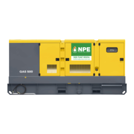
Page 15: Main Parts
The QAS 500 Volvo is an AC generator, built for continuous running at sites where no electricity is available or as stand-by in cases of interruption of the mains. The generator operates at 50 Hz, 400 V - 3 phase, 50 Hz, 230 V - 3 phase and 60 Hz, 480 V - 3 phase. The QAS 500 Volvo generator is driven by a water-cooled diesel engine, manufactured by VOLVO PENTA. - Page 16 Alternator Air filter Coupling Drain flexible engine oil Drain flexible cooling water Engine Filler cap engine oil Filler cap cooling water Fuel filter Battery Oil drain pump Oil filter Engine oil level dipstick Battery switch - 16 -...
-
Page 17: Markings
Markings Indicates the drain for the engine oil. XXXXXXXXXXXXXXX Indicates the partnumbers of A brief description of all markings provided on the the different service packs generator is given hereafter. XXXXXXXXXXXX XXXX XXXX XX XXXXXXXXX XXXX XXXX XX XXXXXXXXX XXXX XXXX XX and of the engine oil. -
Page 18: Safety Devices
The leaking fluid can be removed via drain holes, integrated in the bodywork (roof). To be able to lift secured by drain plugs. Tighten the plugs firmly and the QAS 500 by means of a forklift, rectangular holes 2.3.8 External fuel tank connection check for leakages. -
Page 19: Qc1002™ Controller
Electrical features The electrical features described in this chapter are A1 ..Qc1002™ display Qc1002™ Module standard provided on this generator. For all other F10 ..Fuse electrical features, see “Overview of the electrical options” on page 92. The fuse activates when the current from the battery to the engine control circuit exceeds 2.4.1 Control and indicator panels... -
Page 20: Qc2002™ Controller
2.4.1.2 Qc2002™ controller H0 ..Panel light Qc2002™ Module S2 ..Emergency stop button General description Qc2002™ control panel Push the button to stop the generator in case of an emergency. When the button is pressed, it must be unlocked, before the generator can be restarted. -
Page 21: Qc4002™ Mkii Controller
2.4.1.3 Qc4002™ MkII controller S2 ..Emergency stop button X25 ..Connection block Push the button to stop the generator in case Inside cubicle. Allows customer General description Qc4002™ MkII control panel of an emergency. When the button is connections. pressed, it must be unlocked, before the generator can be restarted. -
Page 22: Output Terminal Board
Qc4002™ MkII module 2.4.2 Output terminal board N13 ..Earth leakage relay Detects and indicates an earth fault current The cubicle provides a terminal board for easier and activates the main circuit breaker Q1. connection of cables. It is situated below the control The detection level can be set at 30 mA fixed and indicator panel. -
Page 23: Dual Frequency
X1 ..Main power supply 2.4.3 Dual frequency 2.4.4 Battery switch Terminals L1, L2, L3, N (= neutral) and PE Dual frequency allows the unit to work at 50 Hz or at The battery switch is situated inside the sound- (= earthing), behind a small transparent 60 Hz with an accuracy of constant load. -
Page 24: Connection
Installation and connection To be able to lift the generator by means of a forklift, Lifting Installation rectangular holes are provided at the bottom of the The lifting eye, to lift the generator by means of a frame. 3.2.1 Indoor installation hoist, is integrated in the bodywork and easily accessible from the outside. -
Page 25: Connecting The Generator
The exposed conductive parts of the electric Wire section Max. current (A) Consult Atlas Copco for measures against the adverse installation must directly Multiple core Single core H07 RN-F influence of non-linear loads. -
Page 26: Connecting The Load
The lowest acceptable wire section and the – Open the door of the control and indicator panel 3.3.3 Connecting the load corresponding maximum cable or conductor length and the transparent door in front of the terminal for multiple core cable or H07 RN-F, at rated current, board X1. -
Page 27: Operating Instructions
Operating instructions Before starting Operating and setting In your own interest, always strictly Qc1002™ observe relevant safety – With the generator standing level, check the instructions. engine oil level and top up if necessary. The oil Do not operate the generator in 4.2.1 Starting level must be near to, but not exceed the high mark... -
Page 28: During Operation
– Check, by means of the generator gauges, that the To start up the unit from a remote location, To stop the unit when the starter switch is in voltage between the phases is identical and that proceed as follows: position , proceed as follows: the rated current is not exceeded. -
Page 29: Setting The Qc1002
4.2.4 Setting the Qc1002™ Following LEDs are used on the Qc1002™: REMOTE MODE: Is used to activate the remote mode. The 4.2.4.1 Pushbutton and LED functions LED indicates if the gen-set is put in Remote Mode. Following pushbuttons are used on the Qc1002 CAN v x.xx.xx Qc1002™:... -
Page 30: Qc1002™ Menu Overview
4.2.4.2 Qc1002™ menu overview 4.2.4.3 Qc1002™ menu description At Qc1002™, the LCD will show following Status display (pop-up window) information: DIAGNOSTIC – in Normal condition (scroll through the information using UP and DOWN): • Status (eg: preheat, crank, run, cooldown, If a special status has elapsed, the active view will be extended stop time, …) entered again automatically. - Page 31 Parameter display LOG list display Battery Voltage display Parameter LOG List Battery 25.2 V 00168.1h This view shows a number of Parameter settings and This view shows the alarm memory and gives access This view shows the Battery voltage and the running gives access to them.
-
Page 32: Parameter List
Fuel level display – Unit Type 1500 00168.1h Unit type 2 for QAS 500 Volvo! Fuel This view shows the engine speed and running hours. – Service Timer 2 reset 00168.1h – Service Timer 1 reset This view shows the Fuel level and the running hours. - Page 33 – Diagnostic Menu – Engine CAN communication This menu is used to power up the engine This menu is used to select the type of engine electronics without starting the engine. When this electronics, the Qc1002™ controller should setting is switched on, electric power will be communicate with via the Canbus.
- Page 34 This is the described menu flow for changing the unit type: Qc1002 CAN Qc1002 CAN v x.xx.xx v x.xx.xx Parameter Running time Unit type Unit type Unit type - 34 -...
-
Page 35: Log List
4.2.4.5 LOG list 4.2.4.6 Remote start operation The unit will keep an event log of the latest 30 events. Installation wirings: Events are: – X25.1 & X25.2 to be wired for the remote start switch. – shutdowns – X25.3 & X25.4 to be wired for the remote –... -
Page 36: Operating And Setting Qc2002
Operating and setting To start up the unit from a remote location, 4.3.2 During operation proceed as follows: Qc2002™ Regularly carry out following checks: – Put the starter switch S20 in position I (ON). – Check the analogue meters (P1-P4) and the Voltage is applied to the Qc2002™... -
Page 37: Stopping
4.3.3 Stopping 4.3.4 Setting the Qc2002™ When the unit is stopped with the STOP button Automatic To stop the unit , proceed as follows: 4.3.4.1 Pushbutton and LED functions operation, it will automatically go to – Switch off the load. Following pushbuttons are used on the Manual Mode. - Page 38 Following LEDs are used on the Qc2002™: Mains Green LED indicates that it is AUTOMATIC: Is used to put the contactor possible to close the Mains unit in manual or automatic Contactor (only in AMF mode), operation. if the Generator contactor is Qc2002 CAN open.
-
Page 39: Qc2002™ Menu Overview
• Active, reactive and apparent power of the 4.3.4.2 Qc2002™ menu overview 4.3.4.3 Qc2002™ menu description generator At Qc2002™, the LCD will show following Status Display (pop-up window) • Generator currents information: • Phase voltages of the mains – in Normal condition (scroll through the •... - Page 40 Parameter display LOG list display DIAGNOSTIC Parameter LOG List If a special status has elapsed, the active view will be This view shows a number of Parameter settings and This view shows the alarm memory and gives access entered again automatically. gives access to them.
- Page 41 Battery voltage display Oil pressure display kWh counter display Battery 25.2 V 3.2bar 4860kWh 00168.1h 00168.1h This view shows the Battery voltage and the running This view shows the Oil pressure and the running This view shows the kWh counter. hours.
-
Page 42: Parameter List
One line voltage - frequency - active power Phase voltages mains display 4.3.4.4 Parameter list display The parameter menu's are pre-programmed ! A password will be asked for when an attempt to M L1-N 230V change a setting is about to be done (user password = G L1-L2 400V M L2-N... - Page 43 Menu's shown on the parameter list LCD: Automatic Mains Failure (AMF) operation Horn delay Genset mode This application is only possible in Horn Delay combination with the AUTO mode. If the Manual Operation mode is Genset Mode 0.0s 20.0s 990.0s selected the AMF operation will NOT function! Island...
- Page 44 Service timer 1 reset Unit menu Engine CAN communication Engine I Comm St 1 Reset Unit C/bar C/bar F/psi These menus are used to reset the service timers. This menu is used to select the units into which This menu is used to select the type of engine When a service timer alarm occurs and is pressures and temperatures will be shown.
- Page 45 M frequency delay MF high voltage MF voltage delay M freq delay MF high volt MF volt delay 9900s 1.0s 990.0s 100% 120% This menu is used to set the delay, which defines how This menu is used to set the maximum limit for the This menu is used to set the delay, which defines how long the mains frequency has to be back within the mains voltage, in % of the nominal voltage (in AMF-...
- Page 46 Overvoltage delay Undervoltage delay Overfrequency delay > Volt Delay < Volt Delay > Freq Delay Overvoltage setpoint Undervoltage setpoint Overfrequency setpoint > Volt < Volt > Freq Undervoltage enable Overfrequency enable Underfrequency enable < Volt enable > Freq enable < Freq enable Enable enable...
-
Page 47: Log List
Underfrequency delay 4.3.4.5 LOG list The unit will keep an event log of the latest 30 events. Events are: < Freq Delay – shutdowns – service timer 1/2 reset Together with each event, the real time of the event Underfrequency setpoint will be stored. -
Page 48: Operating And Setting Qc4002™ Mkii
Operating and setting Qc4002™ MkII 4.4.2 During operation 4.4.3 Stopping Before setting the controller make Regularly carry out following checks: – When in SEMI-AUTO mode: sure that the Qc4002™ MkII is • Press the GB open/close button to open the –... -
Page 49: Setting The Qc4002™ Mkii
4.4.4 Setting the Qc4002™ MkII STOP: Stop of the gen-set if SEMI- SEL: Is used to select the AUTO or MANUAL is selected. underscored entry in the fourth line 4.4.4.1 Pushbutton and LED functions of the display. Following pushbuttons are used on the UP: Increases the value of the GB: Manual activation of Qc4002™... - Page 50 Following LEDs are used on the Qc4002™ MkII The main Qc4002™ MkII control unit includes 5 (GB) ON LED green light indicates that the LEDs generator breaker is closed. LED yellow light indicates that the Qc4002 generator breaker has received a command to close on a black BUS, but the breaker is not yet closed due to interlocking of the GB.
-
Page 51: Qc4002™ Mkii Menu Overview
V2 view – The view shows some generator 4.4.4.2 Qc4002™ MkII menu overview measurements. Main View – In the V1 view the user can scroll up and down to The display has 4 different lines. The information on 15 configurable screens showing different these lines can change, depending on which view is measurements of the generator, the bus and the used. - Page 52 If you select SETUP then you get the following view: Scrolling down will give all the protection The user can scroll through this list and select one set parameters: point with the SEL button. After selection of SP the following view will be –...
- Page 53 – 9000 Software version – 9020 Service port – 911X User password Level 2 and Level 3 passwords can only be set through the Atlas Copco Utility Software PC Software. – 9120 Service menu – 9130 Single/Split/Three phase – 9140 Angle comp. BB/G Use the UP and DOWN buttons to change the settings and the SEL button to store the new setting.
-
Page 54: Changing Settings
4.4.4.3 Changing settings Menu flow: The menu flow is similar in the CONTROL SETUP, I/O SETUP and SYSTEM SETUP. For more details on the Setup menu we refer to the Qc4002™ MkII User Manual. - 54 -... -
Page 55: Standard Modes
When operating in AUTO mode the STOP and GB Open/Close button In order to receive the default parameters for your unit, please contact Atlas Copco Service staff. will not function. Semi-Auto mode In semi-auto mode the operator has to initiate all sequences. -
Page 56: Standard Applications
Block mode 4.4.4.5 Standard applications Island operation When the block mode is selected, the unit is locked In the Qc4002™ MkII module 10 application types Generator for certain actions. This means that it cannot start the can be selected. A combination of each application breaker LOAD gen-set or perform any breaker operations. - Page 57 – For Remote Start operation: – AMF with back synchronisation: Peak Shaving (PS) operation • wire the RS switch between X25.9 & X25.10. When the mains returns, the unit will synchronise Generator Mains the mains breaker to the busbar when the ‘Mains –...
- Page 58 – Mains breaker control lines have to be wired to Installation wirings Fixed Power (FP) operation X25.13/X25.14/X25.15/X25.16. These terminals – The link between X25.10/X25.11 has to be are voltage free contacts. The power for the MB Generator Mains removed. breaker breaker LOAD has to be supplied by the customer (24 Vdc/...
- Page 59 Load Take Over (LTO) operation Installation wirings Mains Power Export (MPE) operation – The link between X25.10 & X25.11 has to be Generator Mains Generator Mains removed. breaker LOAD breaker breaker LOAD breaker – Mains breaker feedback lines have to be wired to X25.10/X25.11/X25.12.
- Page 60 Installation wirings Transformer Maintenance (TM) operation Installation wirings – The link between X25.10 & X25.11 has to – The link between X25.10 & X25.11 has to be beremoved. removed. – Plug the Transformer Maintenance Box cables – Mains breaker feedback lines have to be wired to into Transformer Maintenance Box connectors X25.10/X25.11/X25.12.
- Page 61 Installations are possible with stand-alone generators Example: Installation with 3 gensets Multiple gen-sets with load sharing or with the Mains (extra Qc4002™ MkII Mains is In this application the units are enabled to share the G1 = 300 kW; G2 = 200 kW; G3 = 200 kW. then needed).
-
Page 62: Paralleling
The priority on starting and stopping the generators Installation wirings 4.4.4.6 Paralleling can be chosen on priority settings or on the amount of Prior to starting parallel operation of two generators, running hours. In manual mode the start and stop Genset 1 Genset 2 Genset 3... -
Page 63: Overview Of Applications
Only with Transformer Maintenance Box (*) A Power Transducer is a device that measures the actual power of the mains and which translates this into a 4...20 mA signal towards the Qc4002™ MkII module. For details, please contact Atlas Copco. - 63 -... - Page 64 The installation can contain up to 16 Qc4002™ MkII modules. If the Mains is included in the installation, then an extra Qc4002™ MkII module is required. The installation can be monitored and controlled via the PMS Software Package. For details on this application, please contact Atlas Copco. - 64 -...
- Page 65 Do not put this value above 60 seconds to avoid any possible damage. 4. For more information on the Qc4002™ MkII module and its applications, we refer to the Qc4002™ MkII User manual and the Qc4002™ Application data sheets. If you need more assistance, please contact Atlas Copco. - 65 -...
-
Page 66: Operating The Eberspächer Preheater (Option)
Operating the Eberspächer Preheater (option) It is possible to override a fault shut-down by briefly Before performing any maintenance, switching the heater off and then on again. always switch off the preheater and remove the fuse or disconnect the heater Do not repeat this action more than from the battery. -
Page 67: General
4.5.2 General Setting heating period Switching OFF the heater – Press button (1) longer then 3 sec.; time blinks. – Press button (4). The heater will run idle for about – When no button is pressed the display will return 3 minutes. -
Page 68: Maintenance
2912 4507 06 For the most important subassemblies, Atlas Copco has developed service kits that combine all wear parts. These service kits offer you the benefits of genuine parts, save on administration costs and are offered at reduced price, compared to the loose components. Refer to the parts list for more information on the contents of the service kits. - Page 69 50 hrs Every 500 Every 1000 Every 2000 Maintenance schedule Daily after initial Yearly hours hours hours start-up Service pak 2912 4505 04 2912 4506 05 2912 4507 06 Inspect/Adjust fan/alternator belt Replace fan/alternator belt Measure alternator insulation resistance (11) Test Earth Leakage Relay (12) Check emergency stop (12) Clean radiator (1)
- Page 70 Inspect waterpump Inspect charging alternator Inspection by Atlas Copco service technician Generators in standby application have to be tested on a regular basis. At least once a month the engine should run for one hour. If possible a high load (> 30%) should be applied so that the engine reaches its operating temperature.
-
Page 71: Use Of Maintenance Schedule
2913 0028 00: refractometer The order number of the Service Paks are listed in the 2913 0029 00: pH meter Atlas Copco Parts list (ASL). Order Service Paks at your local Atlas Copco dealer. (8) See section “Before starting”. (9) Replace all rubber flexibles every 5 years, according to DIN20066. -
Page 72: Preventing Low Loads
Test mode without the requirement of a load bank. For more info on this operation, please contact your Atlas Copco Service Center. Check the engine oil level by using the oil level dipstick (OLD). If necessary, top up with oil. -
Page 73: Engine Oil And Oil Filter Change
– The pH-meter can be ordered from Atlas Copco – Top up the engine oil level. with part number 2913 0029 00. – Run the engine for 1 minute and check the oil –... -
Page 74: Topping Up Of Coolant
Flush high engine operating temperatures. – Flush twice with clean water. Used coolant must – A refractometer can be ordered from Atlas Copco be disposed or recycled in accordance with laws with part number 2913 0028 00. and local regulations. -
Page 75: Adjustments And Service Procedures
Adjustments and service procedures – Keep the water cooler (2) clean to maintain the 5.5.1 Cleaning coolers 5.5.2 Cleaning fuel tank cooling efficiency. – The engine water cooler is accessible via the service door (1) at the front of the unit. Remove any dirt from the coolers with a fibre brush. -
Page 76: Battery Care
– Fill each cell with electrolyte until the level If a battery starts to need excessive make-up water, 5.5.3 Battery care reaches 10 to 15 mm above the plates, or to the this points to overcharging. Most common causes are Before handling batteries, read the level marked on the battery. -
Page 77: Servicing Air Filter Engine
Servicing air filter engine 5.5.4.2 Recommendation 5.5.4.4 Replacing the air filter element – Release the snap clips (1) and remove the dust trap The Atlas Copco air filters are 5.5.4.1 Main parts (2). Clean the trap. specially designed – Remove the element (4) from the housing (5). -
Page 78: Replacing Fuel Filter Element
Specifications PAROIL – Clean the adapter head sealing surface. Lightly oil PAROIL from Atlas Copco is the ONLY oil tested the gasket of the new element and screw the latter and approved for use in all engines built into Atlas... -
Page 79: Engine Coolant Specifications
PAROIL has an excellent Total Base Number (TBN) good quality water (distilled or de-ionised), special index. Atlas Copco PAROIL E Mission Green is retention and more alkalinity to control acid coolant additives and if necessary freeze protection. - Page 80 PARCOOL EG is the only coolant that has been Liter cu.ft number tested and approved by all engine manufacturers currently in use in Atlas Copco compressors and 0.175 1604 5308 00 generators. 1604 5307 01 Atlas Copco's PARCOOL EG extended life coolant is...
-
Page 81: Checks And Trouble Shooting
Checks and trouble Checks shooting 6.1.1 Checking voltmeter P4 Never perform a test run with – Put a voltmeter in parallel with voltmeter P4 on connected power cables. Never the control panel. touch electrical connector – Check that the read-out of both voltmeters is the without a voltage check. -
Page 82: Alternator Troubleshooting
Alternator troubleshooting Symptom Possible cause Corrective action Alternator gives 0 Volt Blown fuse. Replace fuse. Excite the alternator by applying a 12V battery voltage with a 30 No residual voltage. resistor in series on the + and - terminals of the electronic regulator, respecting the polarities. -
Page 83: Solving Controller Alarms
Solving controller alarms GENERATOR EMERGENCY 6.4.1 Qc1002™ and Qc2002™ alarms OVERVOLTAGE STOP and remedies 6.4.1.1 Alarm overview GENERATOR UNDER- START FAILURE Possible alarms appearing in the alarm list: VOLTAGE GENERATOR LOW OIL OVER- PRESSURE STOP FAILURE FREQUENCY GENERATOR HIGH COOLANT UNDER- HZ/V FAILURE TEMPERATURE... - Page 84 Displaying the engine DM1 alarm SPN97 "WATER IN FUEL" SPN175 "OIL TEMP" Besides some engine specific alarms shown in the water in fuel oil temperature standard alarm list, also all Diagnostic messages SPN98 "OIL LEVEL" SPN190 "SPEED" DM1 (active alarms) can be shown on the display. oil level speed Use the UP or DOWN buttons until DM1 is shown on...
-
Page 85: Fail Classes
General groups of Alarms 6.4.1.3 Solving alarms – Warning: Alarm LED lights up + Alarm pop-up appears on the display + Alarm relay is empowered (if configured) – Trip of GB: ‘Warning’ actions + Generator Contactor opens – Trip and Stop: ‘Trip of GB’ actions + unit stops In case an Alarm occurs, a pop-up window will after Cooldown automatically be displayed for as long as the alarm is... - Page 86 Menu flow This is the described menu flow for solving alarms: Qc1002 CAN Alarm List Alarm List v x.xx.xx 1 Alarm(s) 0 Alarm(s) SOLVE PROBLEM See next page Alarm List 0 Alarm(s) - 86 -...
- Page 87 Battery broken Replace battery. Bad connection Check wiring. Low oil pressure Not enough oil Fill oil till appropriate level. Check for leaks. Sensor broken Replace sensor. Oil sump broken Check or contact Atlas Copco. Bad connection Check wiring. - 87 -...
-
Page 88: Qc4002™ Mkii Alarms And Remedies
6.4.2 Qc4002™ MkII alarms and remedies 6.4.2.1 Fail Classes Engine stopped: 6.4.2.2 Diagnostics menu All the activated alarms of the module are configured The diagnostics menu can be entered via channel – Alarm: Block engine start. with a fail class. The fail class defines the category of 6700. -
Page 89: Solving Alarms
6.4.2.3 Solving alarms Menu flow Qc4002 Qc4002 Qc4002 SOLVE PROBLEM See page 87 Qc4002 - 89 -... -
Page 90: Storage Of The Generator
Storage of the generator Storage Preparing for operation after storage – Store the generator in a dry, frost-free room which is well ventilated. Before operating the generator again, remove the wrapping, VCI paper and silica gel bags and check the –... -
Page 91: Disposal
(for example sand, sawdust) and recyclable materials. dispose it according the applicable local disposal Your Atlas Copco generator consists for the most part regulations. Do not drain into the sewage system or of metallic materials, that can be remelted in surface water. -
Page 92: Options Available For Qas 500 Volvo Units
Overview of the electrical operational. options The engine control circuit diagrams and the power circuit diagrams for the standard QAS 500 Volvo The following electrical options are available: units, for the units with options and for the units with – Automatic battery charger... -
Page 93: Outlet Sockets (S)
9.3.3 Outlet sockets (S) Q2 ..Circuit breaker for X2 Q6 ..Circuit breaker for X6 Interrupts the power supply to X2 when a Interrupts the power supply to X6 when a A brief description of all outlet sockets and circuit short-circuit occurs at the load side, or when short-circuit occurs at the load side, or when breakers provided on the generator is given hereafter:... -
Page 94: Dual Voltage (2V)
X4 ..3-phase outlet socket 9.3.4 Dual voltage (2V) Q1.1 ..Circuit breaker for low voltage, high current Provides phase L1, L2, L3, neutral and The dual voltage option is only earthing. Interrupts the low voltage power supply available on 50 Hz units, towards X1 when a short-circuit occurs at combination with the Qc2002™... -
Page 95: Electricité De France" (Edf)
The selection between the two modes is done by 9.3.5 “Electricité de France” (EDF) Changing the operation mode from means of S10. When the EDF-option is installed, the unit operates as standard unit to EDF-unit or vice a standard unit when the neutral and the PE terminals S10 .. -
Page 96: Cosmos
Consult the Cosmos manual for a descprition of LED connections have to be made on X25. indications. Connect 1 to 1, 2 to 2,... 8 to 8. For information about COSMOS™, consult your local Atlas Copco dealer. - 96 -... -
Page 97: Overview Of The Mechanical Options
Make sure that: Overview of the mechanical options – the big size coupling is used for the inlet. The following mechanical options are available: – the small size coupling is used for the outlet. – Quick couplings An extra clamp needs to be used to guide the fuellines. -
Page 98: Technical Specifications
Technical specifications 10.1 Readings on gauges Gauge Reading Unit Ammeter L1-L3 (P1-P3) Below max. rating Voltmeter (P4) Below max. rating 10.2 Settings of switches Switch Function Activates at Engine coolant temperature Warning 107°C Engine coolant temperature Shut down 112°C 10.3 Specifications of the engine/alternator/unit 50 Hz 60 Hz Rated frequency... - Page 99 Rated voltage 3ph line to line 400 V 480 V Rated voltage 3ph line to line lower voltage (optional) 230 V Rated current 3ph 722 A 700 A Rated current 3ph lower voltage (optional) 1255 A Performance class (acc.ISO 8528-5:1993) Single step load acceptance 248 kW 277 kW...
- Page 100 Coolant water water Combustion system direct injection direct injection Aspiration turbocharged turbocharged intercooled intercooled Number of cylinders Swept volume 16.12 l 16.12 l Speed governing electronic electronic Governer type EMS 2 EMS 2 Capacity of oil sump - initial fill 42 l 42 l Capacity of cooling system...
- Page 101 Fault current protection Residual current release IDn 0.030-30 A 0.030-30 A Insulation resistance 10-100 kOhm 10-100 kOhm Outlet sockets (optional) domestic (1x) 2p + E 16 A/230 V CEE form (1x) 3p + N + PE 16 A/400 V CEE form (1x) 3p + N + PE 32 A/400 V CEE form (1x)
- Page 102 Notes Reference conditions for engine performance to ISO 3046-1. See derating diagram or consult the factory for other conditions. At reference conditions unless otherwise stated. Rating definition (ISO 8528-1): LTP: Limited Time Power is the maximum electrical power which a generating set is capable of delivering (at variable load), in the event of a utility power failure (for up to 500 hours per year of which a maximum of 300 hours is continuous running).
- Page 103 60 hz Temperature Height (°C) 1000 1500 2000 2500 3000 3500 4000 For use of generator outside these conditions, please contact Atlas Copco. - 103 -...
-
Page 104: Conversion List Of Si Units Into
10.4 Conversion list of SI units 10.5 Dataplate Maximum permitted total weight of the vehicle into British units Maximum permitted front axle load Maximum permitted rear axle load 1 bar 14.504 psi Company code 0.035 oz Product code 1 kg 2.205 lbs Unit serial number 1 km/h... - Page 105 Circuit diagrams - 105 -...
- Page 106 9822 0993 25/05 Applicable for QAS 500 - Qc1002™, Engine Circuit to Control Module A1 S11d ded. 60Hz Sx=Remote Start/Stop-switch max. 24Vdc, 4A Plant Contactor 12 13 17 18 33 34 Output: 24Vdc, max. 8Adc1 Customer's Installation (see Instruction Manual)
- Page 107 E F G Cubicle Cubicle Canopy Canopy Position of Relay Cont. Cubicle pin C5 Unit QAS125 not connected QAS150 not connected QAS200 not connected QAS275 connected QAS325 connected QAS500 connected QAS600 connected Wire size : Colour code : Connect to Cubicle aa = 0.5 mm²...
- Page 108 Control module (configure in UNIT-type 2) Fuel level sensor Fuse Fuse 15A DC (O) Battery 24V Panel light Aux.relay for Y7 (O) Engine control relay Starter motor Eberspacher fuel pump (O) Eberspacher timer (O) Eberspacher (O) P1-3 A-meters V-meter Resistor 120 ohm Resistor 470 ohm 7W (O) Battery switch Emergency stop button...
- Page 109 - 109 -...
- Page 110 9822 0993 26/04 Applicable for QAS 500 - Qc2002™, Engine Circuit towards to Circ.Diagr POWER X25.8 X9.441 & X9.442 b6 b0 a0 a0 a0 a0 a0 a6 a2 26 27 37 38 53 54 57 58 Fx Fx Fx Fx to Circ.Diagr POWER...
- Page 111 Legend Wire size : Colour code : aa = 0.5 mm² 0 = black 1 mm² 1 = brown b = 1.5 mm² 2 = red = 2.5 mm² 3 = orange 4 mm² 4 = yellow 6 mm² 5 = green = 10 mm²...
- Page 112 Generator control unit Fuel level sensor Fuse 10A DC Fuse 15A DC (O) Battery 24Vdc Panel light Aux.relay for Y7 (O) Engine control relay Starter motor Eberspacher fuel pump (O) Eberspacher timer (O) Eberspacher (O) P1-3 A-meters V-meter Resistor 120 ohm Resistor 470 ohm 7W (O) Battery switch Emergency stop...
- Page 113 - 113 -...
- Page 114 9822 0993 30/04 Applicable for QAS 500 - Qc1002™, Qc2002™, Power Circuit T1-3 P1-3 Wire size (O) QAS500 (O) QAS275-QAS325 QAS275 400A 400/5A 0-400A QAS325 470A 600/5A 0-600A QAS500 720A 800/5A 0-800A 2x lx 400V/480V 400V/480V Breaker Set. Frequency Selection...
- Page 115 Cubicle Canopy (O) 1-Phase Socket See Circ.Diagr Engine See Circ.Diagr Engine S11b (O) 3-Phase Sockets hx54 30mA 125A 125A PE-EDF See Note 2 (O) N-EDF - 115 -...
- Page 116 F1-3 Fuse 4A Alternator Automatic voltage regulator Earth leakage relay Main circuit breaker Circuit breaker (16A+30mA) Circuit breaker (125A - 3ph) Circuit breaker (63A - 3ph) Circuit breaker (32A - 3ph) Circuit breaker (16A - 3ph) Coolant heater Voltage adjustment potmeter (1kOhm) Emergency stop (S2a see Engine Circuit) S11a,b...
- Page 117 - 117 -...
- Page 118 F1-3 Fuse 4A 9822 0993 31/01 Alternator Applicable for QAS 500 - Dual voltage Automatic voltage regulator Earth leakage relay Q1.1 Circuit breaker (lower voltage) Q1.2 Circuit breaker (higher voltage) Coolant heater Voltage adjustment potmeter Emergency stop 400Vy/230Vd S10a (S2a see Engine Circuit)
- Page 119 0-800A 2x lx nx = 150 mm² EPR-CSP to BS6195 4C QAS 325 800A 470A 800/5A 0-800A 2x mx px = 185 mm² EPR-CSP to BS6195 4C QAS 500 1250A 720A 1500/5A 0-1500A 3x mx 2x lx - 119 -...
- Page 120 9822 0993 49/00 Applicable for QAS 500 - Qc4002™, Engine & Power Circuit MAINS SUPPLY (3P+N+PE) Note "M": Remove link "M" when N L1 L1 L2 L3 Sx=Remote parallelling with the mains. Start/Stop-switch In AMF-mode or in case of mains...
- Page 121 Frequency Selection R450(0) Notes 400V/480V Note 1: The PE-N connection has to be made at the alternator-side of Circuit Breaker Q1. Position of Relay Contacts Terminal strip X11 K200 K201 K202 K203 Legend Note with X11 Wire size : Colour code : T1 T2 T3 S11 a a = 1 mm...
- Page 122 Generator control unit Resistor 47ohm - 7W (O) LCD display Battery switch Fuel level sensor S2a,b,c Emergency stop F1-6 Fuse 250mA Water in fuel switch (O) Fuse 10A DC S11a,b,d Selector switch 50/60Hz Fuse 15A DC (O) Earth leak. disable switch Battery 24Vdc ON/OFF switch Alternator...
- Page 123 - 123 -...
- Page 124 Fuse 6A (see note 1) 9822 0774 31 Fuse 6A (see note 2) Applicable for QAS 500 - COC box F2-4 Fuse 0.25A (see note 1) Contactor mains supply Contactor generator Terminal strip from 3Ph generator from 3Ph mains supply...
- Page 125 - 125 -...
- Page 126 Following documents are provided with this unit: – Test Certificate – EC Declaration of Conformity: EC DECLARATION OF CONFORMITY We, Atlas Copco Airpower n.v., declare under our sole responsibility, that the product Machine name : Power generator ( 400 kW) Machine type : Serial number : Which falls under the provisions of article 12.2 of the EC Directive 2006/42/EC on the approximation of the...
- Page 127 Phone: +32 (0)3 870 21 11 Com. Reg. Antwerp 44651 P.O. Box 100 Boomsesteenweg 957 Fax: +32 (0)3 870 24 43 V.A.T. 403.992.231 B-2610 Wilrijk-Antwerp B-2610 Wilrijk-Antwerp Belgium Belgium For info, please contact your local Atlas Copco representative www.atlascopco.com p.2(2) - 127 -...
- Page 128 - 128 -...
- Page 130 www.atlascopco.com...
Need help?
Do you have a question about the QAS 500 and is the answer not in the manual?
Questions and answers
My QAS 500 has a start failure alarm and can't start
A start failure alarm on an Atlas Copco QAS 500 could be caused by:
- Bad connection: Check wiring.
- Low battery voltage: Battery may be drained; charge the battery or install a charger.
- Charging alternator broken: Measure battery voltage during operation; replace alternator if voltage is not correct.
- Battery broken: Replace the battery.
- Low oil pressure: Fill oil to the correct level and check for leaks.
- Faulty oil pressure sensor: Replace sensor.
- Oil sump broken: Check or contact Atlas Copco.
- Emergency stop activated: Reset it manually after resolving the issue.
These conditions can block engine start and trigger alarms in the diagnostics menu.
This answer is automatically generated