Table of Contents
Troubleshooting

Related Manuals for Atlas Copco QES 9-11 Kd ESF


Summary of Contents for Atlas Copco QES 9-11 Kd ESF
- Page 1 Instruction Manual Instruction Manual for AC Generators English QES 9-11 Kd ESF D1105-E2BG QES 14-16 Kd ESF D1703M-BG QES 20-25 Kd S3A ESF V2403M-BG QES 30-35 Kd S3A ESF V3300DI QES 40-50 Kd S2/S3A ESF V3800DI-T...
- Page 3 QES 9-14-20-30-40 Kd S3A/S2 ESF - 50Hz QES 11-16-25-35-50 Kd S3A/S2 ESF - 60 Hz Instruction Manual for AC Generators Instruction manual .................. 5 Circuit diagrams .................. 115 Original instructions Printed matter N° 2954 8130 00 ATLAS COPCO - PORTABLE ENERGY DIVISION www.atlascopco.com 04/2015...
- Page 4 While every effort has been made to ensure that the information in this manual is correct, Atlas Copco does not assume responsibility for possible errors. Copyright 2015, Grupos Electrógenos Europa, S.A.U., Zaragoza, Spain. Any unauthorized use or copying of the contents or any part thereof is prohibited.
-
Page 5: Table Of Contents
Please read the following instructions carefully before starting to use your machine. While every effort has been made to ensure that the information in this manual is correct, Atlas Copco does not assume responsibility for possible errors. Atlas Copco reserves the right to make changes without prior notice. - Page 6 Maintenance......32 5.5.3.4 Make-up distilled water ....48 Overview of the electrical options .62 5.5.3.5 Periodic battery service ....49 Description of the electrical Maintenance schedules....32 options ..........62 Engine consumable specifications .49 5.1.1 Maintenance schedule for 9.3.1 Automatic battery charger....62 QES 9 and QES 11......32 5.6.1 Engine fuel specifications....49 9.3.2...
- Page 7 Technical specifications ... 69 10.1 Technical specifications for QES 9 and QES 11 units ....69 10.2 Technical specifications for QES 14 and QES 16 units ....78 10.3 Technical specifications for QES 20 and QES 25 units ....87 10.4 Technical specifications for QES 30 and QES 35 units ....96 10.5 Technical specifications for...
-
Page 8: Safety Precautions For On-Site Generators
The policy of Atlas Copco is to provide the users of their Atlas Copco equipment. It is the responsibility of unsafe operating conditions. Take necessary steps to equipment with safe, reliable and efficient products. -
Page 9: General Safety Precautions
The manufacturer does not accept any liability for any Normal ratings (pressures, temperatures, speeds, 14 When working on the unit, wear safety clothing. damage arising from the use of non-original parts and for etc.) shall be durably marked. Depending on the kind of activities these are: safety modifications, additions or conversions made without glasses, ear protection, safety helmet (including Operate the unit only for the intended purpose and... -
Page 10: Safety During Transport And Installation
When - check the towbar, the brake system and the Atlas Copco. the towbar can be positioned vertically, the locking towing eye. Also check the coupling of the device must be applied and kept in good order. -
Page 11: Safety During Use And Operation
- above 85 dB(A): room to be classified as a noise- appropriate protection, at least safety glasses, for otherwise stated in the Atlas Copco Instruction hazardous area and an obvious warning shall be the operator as well as for any bystander. Do not Book (AIB). -
Page 12: Safety During Maintenance And Repair
Parts shall only be replaced by genuine Atlas Copco protection. When a breaker has tripped, reduce the too; but the fact that no dust can be seen is not a replacement parts. - Page 13 18 Maintenance and repair work should be recorded in in or on the machine. Never leave rags or loose or approved by Atlas Copco or the machine an operator’s logbook for all machinery. Frequency clothing near the engine air intake.
-
Page 14: Tool Applications Safety
When connecting an auxiliary battery (AB) in Tool applications safety parallel to the unit battery (CB) with booster cables: Apply the proper tool for each job. With the knowledge connect the + pole of AB to the + pole of CB, then of correct tool use and knowing the limitations of tools, connect the - pole of CB to the mass of the unit. -
Page 15: Main Parts
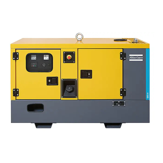
Main parts General description The QES 9-14-20-30-40 and QES 11-16-25-35-50 are AC generators, built for continuous running at sites where no electricity is available or as stand-by in cases of interruption of the mains. The QES 9-14-20-30-40 generators operate at 50 Hz, 400/380/415V 3ph and 230V 1ph. The QES 11-16-25-35-50 generators operate at 60 Hz, 208/220/380V 3ph and 240V 2ph. - Page 16 Alternator Air filter Battery switch Cubicle Drain flexible cooling water Engine Filler cap cooling water Fuel filter Battery Oil filter View A - 16 -...
-
Page 17: Markings
Markings XXX X-XX Engine xxxxxxxxxxx Indicates the drain for the coolant. Fuel tank capacity xxx l Oil sump capacity Markings provide instructions and information. They Cool. system capacity xx l Hyd. oil capacity xx l Alternator xxxxx Tyre pressure also warn of hazards. For convenience and safety, Service Kits Engine Parts Description... -
Page 18: Mechanical Features
Mechanical features The mechanical features described in this chapter are 2.3.4 Bodywork 2.3.7 Drain plugs and filler caps standard provided on this generator. For all other The alternator, the engine, the cooling system, etc. are The drain holes for the engine oil, the coolant and the mechanical features, see chapter “Overview of the enclosed in a sound-insulated bodywork that can be plug for the fuel, are located and labelled on the... -
Page 19: Electrical Features
Electrical features 2.4.2 Qc1011™ control and indicator A1 ..Qc1011™ display panel The electrical features described in this chapter are PA1 ..Ammeter To operate the generator, the QES 9-14-20-30-40 / standard provided on this generator. For all other QES 11-16-25-35-50 control panel contains a PV1 ..Voltmeter electrical features, see chapter “Overview of the Qc1011™... -
Page 20: Output Terminal Board
2.4.3 Output terminal board Q600 ... Main circuit breaker Interrupts the power supply to X10 when a The cubicle provides a terminal board for easier short-circuit occurs at the load side, or when connection of cables. It is situated below the control the earth leak detector (30 mA) or the and indicator panel. -
Page 21: Connection
Installation and connection To be able to lift the generator by means of a forklift, Lifting Installation rectangular slots are provided at the bottom of the The lifting eye, to lift the generator by means of a frame. 3.2.1 Indoor installation hoist, is integrated in the bodywork and easily accessible from the outside. -
Page 22: Connecting The Generator
IT- Wire section Max. current (A) Consult Atlas Copco for measures against the adverse (mm²) Multiple core Single core H07 RN-F system, other protective devices influence of non-linear loads. -
Page 23: Connecting The Load
The lowest acceptable wire section and the – Open the door of the control and indicator panel 3.3.3 Connecting the load corresponding maximum cable or conductor length and the transparent door in front of the terminal for multiple core cable or H07 RN-F, at rated current board X1. -
Page 24: Operating Instructions
Operating instructions Before starting Operating and setting Qc1011™ – With the generator standing level, check the In your own interest, always strictly engine oil level and top up if necessary. The oil observe relevant safety 4.2.1 Manual operation level must be near to, but not exceed the high mark instructions. -
Page 25: Starting Sequence
4. After the starter motor has disengaged, the ‘Safety 4.2.1.2 Starting sequence 4.2.1.4 Stopping sequence On’ timer activates, allowing Oil Pressure, High In manual mode, the set will continue to run until NOTE: There is no start delay in this mode of Engine Temperature, Underspeed, Charge Fail either: operation. -
Page 26: Automatic Operation
NOTE: If the unit has been configured for CAN, 4.2.2 Automatic operation 4.2.2.3 Engine running compatible ECUs will receive the start Once the engine is running and all starting timers NOTE: If a digital input configured to 'panel lock' is command via CAN. -
Page 27: Checks During Operation
4.2.3 Checks during operation Regularly carry out following checks: – Check the analogue meters (PV1-PA1) and the controller display for normal readings. Avoid to let the engine run out of fuel. If it happened, priming will speed up the starting. –... -
Page 28: Setting The Qc1011
4.2.4 Setting the Qc1011™ Following LEDs are used on the Qc1011™: START: Is used to crank the 4.2.4.1 Push button and LED functions angine. Following push buttons are used on the Qc1011™: SCROLL: Is used to scroll the display to show the various instruments. -
Page 29: Module Display
If an alarm becomes active while viewing the Status 4.2.4.2 Module display Icon overview page, the display shows the Alarms page to draw the General operator’s attention to the alarm condition. Display Description The Qc1011™ graphical display shows the generator Appears when a timer is active, for Page overview instrumentation and alarm conditions. -
Page 30: Protections
Back light 4.2.4.4 Front panel configuration Accessing the Front Panel Editor (FPE) The back light will be on if the unit has sufficient Press the STOP and AUTO button simultaneously to This configuration mode allows the operator limited voltage while the unit is turned on. When the unit is enter the editor mode. - Page 31 Editing a parameter The editor automatically exits after 5 1. Enter the editor mode by pressing the STOP and minutes of inactivity to ensure AUTO button simultaneously. security. 2. Press the STOP button to select the required page. 3. Press the START (+) button to select the next parameter or the AUTO (-) button to select the previous parameter within the current page.
-
Page 32: Maintenance
TBA* For the most important subassemblies, Atlas Copco has developed service kits that combine all wear parts. These service kits offer you the benefits of genuine parts, save on administration costs and are offered at reduced price, compared to the loose components. Refer to the parts list for more information on the contents of the service kits. - Page 33 50 hrs Every 250 Every 500 Every 1000 Maintenance schedule Daily after initial Yearly hours hours hours start-up Service pak TBA* TBA* Replace fuel (primary)filter(s) (5) Inspect/Adjust fan/alternator belt Replace fan/alternator belt Measure alternator insulation resistance (11) Test Earth Leakage Relay (12) Check emergency stop (12) Clean radiator (1) Check for obstructions on crankcase breather system / filter and...
- Page 34 Inspect water pump Inspect charging alternator Inspection by Atlas Copco service technician Generators in stand-by application have to be tested on a regular basis. At least once a month the engine should run for one hour. If possible a high load (> 30%) should be applied so that the engine reaches its operating temperature.
- Page 35 50 km Every Maintenance schedule Daily after initial Every 500 km Yearly 1000 km start-up Check tyre pressure Check tyres for uneven wear Check torque of wheel nuts Check coupling head Check height of adjusting facility Check towbar handbrake lever spring actuator, reversing lever, linkage and all movable parts for ease of movement Grease coupling head, towbar bearings at the housing of the overrun brake Check brake system (if installed) and adjust if necessary...
- Page 36 Reduce service interval in heavy duty application. (6) See chapter “Engine oil specifications”. (7) The following part numbers can be ordered from Atlas Copco to check on inhibitors and freezing points: • 2913 0028 00: refractometer •...
-
Page 37: Maintenance Schedule For Qes 14-20-30-40 And Qes 16- 25-35-50
TBA* For the most important subassemblies, Atlas Copco has developed service kits that combine all wear parts. These service kits offer you the benefits of genuine parts, save on administration costs and are offered at reduced price, compared to the loose components. Refer to the parts list for more information on the contents of the service kits. - Page 38 50 hrs Every 500 Every 1000 Maintenance schedule Daily after initial Yearly hours hours start-up Service pak TBA* TBA* Test Earth Leakage Relay (12) Check emergency stop (12) Clean radiator (1) Check for obstructions on crankcase breather system / filter and hoses Drain condensate and water from spillage-free frame or catch basin (8) Check for leaks in engine-, air-, oil-, or fuel system Inspect/Replace hoses and clamps...
- Page 39 Service pak TBA* TBA* Inspection by Atlas Copco service technician Generators in stand-by application have to be tested on a regular basis. At least once a month the engine should run for one hour. If possible a high load (> 30%) should be applied so that the engine reaches its operating temperature.
- Page 40 50 km Maintenance schedule Daily after initial Every 500 km Every 1000 km Yearly start-up Check tyre pressure Check tyres for uneven wear Check torque of wheel nuts Check coupling head Check height of adjusting facility Check towbar handbrake lever spring actuator, reversing lever, linkage and all movable parts for ease of movement Grease coupling head, towbar bearings at the housing of the overrun brake Check brake system (if installed) and adjust if necessary...
-
Page 41: Use Of Maintenance Schedule
The order number of the Service Paks are listed in the • 2913 0028 00: refractometer Atlas Copco Parts list (ASL). Order Service Paks at • 2913 0029 00: pH meter your local Atlas Copco dealer. (8) See chapter “Before starting”. -
Page 42: Preventing Low Loads
Low boost pressure will cause oil comes first. leakage over the turbo shaft seal. It is recommended that a unit is always used with a For more info, please contact your Atlas Copco load > 30% of nominal. Corrective actions should be Service Center. 5.2.2... -
Page 43: Alternator Maintenance Procedures
Alternator maintenance Engine maintenance procedures procedures Refer to the engine’s operator manual for full 5.3.1 Measuring the alternator maintenance, including instructions for changing the insulation resistance oil and coolant and replacing the fuel, oil and air filters. A 500 V megger is required to measure the alternator insulation resistance. -
Page 44: Coolant Check
– Top up the engine oil level. – A refractometer can be ordered from Atlas Copco – Run the engine for 1 minute and check the oil Visual check with part number 2913 0028 00. -
Page 45: Replacing The Coolant
The engine must be stopped before – From the Atlas Copco Instruction book, determine cleaning performing the amount of PARCOOL EG required and pour maintenance activity to the air filter into the radiator top tank. -
Page 46: Replacing Fuel Filter Element
5.4.4.2 Recommendation 5.4.4.4 Replacing the air filter element 5.4.5 Replacing fuel filter element – Release the snap clips (1) and remove the dust trap – New elements must be inspected for tears or (2). Clean the trap. punctures before installation. –... -
Page 47: Adjustments And Service Procedures
Adjustments and service procedures – Remove the service plate at the front of the unit 5.5.1 Cleaning coolers 5.5.2 Cleaning the fuel tank (1) to get access to the engine water cooler (2). Keep the engine water cooler clean to maintain the cooling efficiency Remove any dirt from the coolers with a fibre brush. -
Page 48: Battery Care
5.5.3 Battery care 5.5.3.1 Electrolyte 5.5.3.3 Recharging a battery Before and after charging a battery, always check the Before handling batteries, read the Read safety instructions electrolyte level in each cell; if required, top up with relevant safety precautions and act carefully. -
Page 49: Periodic Battery Service
ISO 3448, as follows: Specifications PAROIL regulator maladjusted, poor performance of generator, etc... PAROIL from Atlas Copco is the ONLY oil tested and approved for use in all engines built into Atlas Engine Type of lubricant Copco compressors and generators. - Page 50 Copco PAROIL Extra is designed to provide index. Atlas Copco PAROIL E Mission Green is extended periods. excellent lubrication from start-up in temperatures as designed to provide a high level of performance and low as -25°C (-13°F).
-
Page 51: Engine Coolant Specifications
Liter cu.ft filler cap while coolant is hot. number currently in use in Atlas Copco compressors and The system may be under pressure. generators. 0.175 1604 5308 01 Remove the cap slowly and only... -
Page 52: Checks And Trouble Shooting
Checks and trouble Checks Engine troubleshooting shooting The table below gives an overview of the possible 6.1.1 Checking voltmeter PV1 engine problems and their possible causes. Never perform a test run with – Put a voltmeter in parallel with voltmeter PV1 on connected power cables. - Page 53 – Incorrect valve tip clearances. Not enough power The pressure of the lubricating oil is too low – Restriction in a fuel pipe. – Wrong grade of lubricating oil. – Engine overload. – Fault in fuel lift pump. – Not enough lubricating oil in sump. Blue or white exhaust smoke –...
- Page 54 – Fault in cold start system. Crankcase pressure – Restriction in breather pipe. – Restriction in fuel tank vent. – Vacuum pipe leaks or fault in exhaust. – Restricted movement of engine speed control. – Engine temperature is too high. Bad compression –...
-
Page 55: Alternator Troubleshooting
Alternator troubleshooting Symptom Possible cause Corrective action Alternator gives 0 Volt Blown fuse. Replace fuse. Excite the alternator by applying a 12V battery voltage with a 30 Ω No residual voltage. resistor in series on the + and - terminals of the electronic regulator, respecting the polarities. -
Page 56: Solving Qc1011™ Controller Alarms
Solving Qc1011™ controller alarms 6.4.1 General When an alarm is present, the alarm LED will illuminate, if configured. The LCD display will show an icon to indicate the failure. Warnings Warnings are non-critical alarm conditions and do not affect the operation of the generator system, they serve to draw the operators attention to an undesirable condition. -
Page 57: Alarm Icon Overview
6.4.2 Alarm icon overview Auxiliary inputs Auxiliary inputs can be user configured and will display the message as written by the user. Fail to start The engine has not fired after the preset number of start attempts. The module has detected a condition that indicates that the engine is running when it has been instructed to stop. - Page 58 Battery under voltage / Battery over voltage The DC supply has fallen below or risen above the low/high volts setting level. The generator output voltage has fallen below the pre-set pre-alarm setting after the Safety On Generator under voltage timer has expired. Generator over voltage The generator output voltage has risen above the pre-set pre-alarm setting.
- Page 59 Either the configuration file or engine file memory is corrupted. Contact your supplier for Internal memory error assistance. - 59 -...
-
Page 60: Storage Of The Generator
Storage of the generator Storage Preparing for operation after storage – Store the generator in a dry, frost-free room which is well ventilated. Before operating the generator again, remove the wrapping, VCI paper and silica gel bags and check the –... -
Page 61: Disposal
(for example sand, sawdust) and recyclable materials. dispose it according the applicable local disposal Your Atlas Copco generator consists for the most part regulations. Do not drain into the sewage system or of metallic materials, that can be remelted in surface water. -
Page 62: Options Available
Options available Circuit diagrams Overview of the electrical Description of the electrical options options The engine control circuit diagrams and the power circuit diagrams for the standard QES 9-14-20-30-40 The following electrical options are available: and QES 11-16-25-35-50 units, for the units with 9.3.1 Automatic battery charger –... -
Page 63: Battery Switch
The battery charger provides multi-stage intelligent 9.3.2 Battery switch 9.3.4 Single phase charging: The battery switch is situated inside the sound- Only available for 50 Hz units. – Constant current: maximum current available insulated bodywork. It allows to open or to close the during charge recovery phase electrical connection between the battery and the The single phase option provides single phase output... -
Page 64: Dual Phase
9.3.5 Dual phase 9.3.6 Outlet sockets (S) - 3-phase A brief description of all outlet sockets and circuit Q602 Only available for 60 Hz units. breakers provided on the generator is given hereafter: XS1 ..3-phase outlet socket (400/480 V AC) The dual phase option provides two phase output voltage (e.g. -
Page 65: It-Relay
9.3.7 Outlet sockets (S) - 1-phase 9.3.8 IT-relay A brief description of all outlet sockets and circuit Q602 breakers provided on the generator is given hereafter: Not available for 60 Hz units. XS2..1-phase outlet socket (230 V AC) The generator is wired for an IT network i.e. no Provides phase L1, neutral and earthing. - Page 66 X10 ..Main power supply (400 V AC) Terminals L1, L2, L3, N (= neutral) and PE (= earthing), hidden behind the control panel door and behind a small transparent door. EM1 ..Insulation monitoring relay Checks insulation resistance activates Q600 when insulation...
-
Page 67: Overview Of The Mechanical Options
Overview of the mechanical Description of the View inside options mechanical options The following mechanical options are available: 9.5.1 External fuel tank connection – External fuel tank connection (with/without quick (with/without quick couplings) couplings) The option external fuel tank connection allows to –... -
Page 68: Oil Drain Pump
9.5.2 Oil drain pump To maintain the undercarriage 9.5.4 Galvanized skid with forklift – Check the tightness of the towbar bolts, the axle slots The oil drain pump facilitates oil change. bolts and the wheel nuts at least twice a year and To be able to lift the generator by means of a forklift, after the initial 50 hours of operation. -
Page 69: Technical Specifications
Technical specifications 10.1 Technical specifications for QES 9 and QES 11 units 10.1.1 Readings on gauges Gauge Reading Unit Ammeter L3 (PA1) Below max. rating Voltmeter (PV1) Below max. rating 10.1.2 Settings of switches Switch Function Activates at Engine oil pressure Shut down 0.5 bar Engine coolant temperature... - Page 70 Rated active power (PRP) 7.2 kW 7.2 kW 7.2 kW 6.7 kW Performance data Rated apparant power (PRP) 9.0 kVA 9.0 kVA 9.0 kVA 6.7 kVA 2) 3) 4) 5) Rated voltage line to line 400 V 380 V 415 V 230 V Rated current 3ph 13.0 A...
- Page 71 Standard IEC34-1 IEC34-1 IEC34-1 IEC34-1 Alternator 4) ISO 8528-3 ISO 8528-3 ISO 8528-3 ISO 8528-3 Make MeccAlte MeccAlte MeccAlte MeccAlte Model ECP3-1LN/4 ECP3-1LN/4 ECP3-1LN/4 ECP3-2L Rated output, class H temp. rise - 3ph 11 kVA 11 kVA 11 kVA 9 kVA rating type acc.
- Page 72 Fault current protection Residual current release IDn 0.030-30 A 0.030-30 A 0.030-30 A 0.030-30 A Insulation resistance (optional) 1-200 kOhm 1-200 kOhm 1-200 kOhm 1-200 kOhm domestic (1x) domestic (1x) Outlet sockets (optional) (optional) (optional) 2p + PE 2p + PE 16 A 230 V 16 A 230 V CEE form (1x)
- Page 73 QES 11 QES 11 QES 11 QES 11 208/120 V - 3ph 220/127 V - 3ph 240/120 V - 2ph 380/220 V - 3ph Rated frequency 60 Hz 60 Hz 60 Hz 60 Hz Reference conditions Rated speed 1800 rpm 1800 rpm 1800 rpm 1800 rpm...
- Page 74 Capacity of fuel tank Single step load capability Mode of operation Application data Site land use land use land use land use Operation single single single single Start-up and control mode manual/automatic manual/automatic manual/automatic manual/automatic Start-up time unspecified unspecified unspecified unspecified Mobility/Config.
- Page 75 Swept volume 1.12 l 1.12 l 1.12 l 1.12 l Speed governing mechanical mechanical mechanical mechanical Capacity of oil sump - initial fill 5.1 l 5.1 l 5.1 l 5.1 l Capacity of cooling system 3.1 l 3.1 l 3.1 l 3.1 l Electrical system 12 Vdc...
- Page 76 Notes Reference conditions for engine performance to ISO 3046-1. See derating diagram or consult the factory for other conditions. At reference conditions unless otherwise stated. Rating definition (ISO 8528-1): LTP: Limited Time Power is the maximum electrical power which a generating set is capable of delivering (at variable load), in the event of a utility power failure (for up to 500 hours per year of which a maximum of 300 hours is continuous running).
- Page 77 Derating Temperature Height (°C) 1000 1500 2000 2500 3000 3500 4000 For use of generator outside these conditions, please contact Atlas Copco. - 77 -...
-
Page 78: 10.2 Technical Specifications For Qes 14 And Qes 16 Units
10.2 Technical specifications for QES 14 and QES 16 units 10.2.1 Readings on gauges Gauge Reading Unit Ammeter L3 (PA1) Below max. rating Voltmeter (PV1) Below max. rating 10.2.2 Settings of switches Switch Function Activates at Engine oil pressure Shut down 0.5 bar Engine coolant temperature Shut down... - Page 79 Rated current 3ph 19.9 A 20.9 A 19.2 A 45.2 A Performance class (acc.ISO 8528-5:1993) Single step load acceptance 11 kW 11 kW 11 kW 100% 100% 100% Frequency droop isochroneous isochroneous isochroneous isochroneous Fuel consumption at no load (0%) 1.17 kg/h 1.17 kg/h 1.17 kg/h...
- Page 80 Rated output, class H temp. rise - 3ph 15 kVA 15 kVA 15 kVA 11.5 kVA rating type acc. ISO 8528-3 125/40°C 125/40°C 125/40°C 125/40°C Degree of protection (IP index acc. NF EN 60-529) IP 23 IP 23 IP 23 IP 23 Insulation stator class Insulation rotor class...
- Page 81 domestic (1x) domestic (1x) Outlet sockets (optional) (optional) (optional) 2p + PE 2p + PE 16 A 230 V 16 A 230 V CEE form (1x) CEE form (1x) 3p + N + PE 2p + PE 16 A 400 V 16 A 230V CEE form (1x) 3p + N + PE...
- Page 82 QES 16 QES 16 QES 16 QES 16 208/120V - 3ph 220/127V - 3ph 240/120V - 2ph 380/220 V - 3ph Rated frequency 60 Hz 60 Hz 60 Hz 60 Hz Reference conditions Rated speed 1800 rpm 1800 rpm 1800 rpm 1800 rpm Generator service duty Absolute air inlet pressure...
- Page 83 Capacity of fuel tank 55 l 55 l 55 l 55 l Single step load capability 12.8 kW 13.3 kW 100% 100% 100% 100% Mode of operation Application data Site land use land use land use land use Operation single single single single...
- Page 84 Swept volume 1.7 l 1.7 l 1.7 l 1.7 l Speed governing electronic electronic electronic electronic Capacity of oil sump - initial fill Capacity of cooling system Electrical system 12 Vdc 12 Vdc 12 Vdc 12 Vdc Maximum permissible load factor of PRP during 100% 100% 100%...
- Page 85 Notes Reference conditions for engine performance to ISO 3046-1. See derating diagram or consult the factory for other conditions. At reference conditions unless otherwise stated. Rating definition (ISO 8528-1): LTP: Limited Time Power is the maximum electrical power which a generating set is capable of delivering (at variable load), in the event of a utility power failure (for up to 500 hours per year of which a maximum of 300 hours is continuous running).
- Page 86 Derating factor (%) Temperature Height (PRP at 50Hz, 400V) (°C) 1000 1500 2000 2500 3000 3500 4000 For use of generator outside these conditions, please contact Atlas Copco. - 86 -...
-
Page 87: 10.3 Technical Specifications For Qes 20 And Qes 25 Units
10.3 Technical specifications for QES 20 and QES 25 units 10.3.1 Readings on gauges Gauge Reading Unit Ammeter L3 (PA1) Below max. rating Voltmeter (PV1) Below max. rating 10.3.2 Settings of switches Switch Function Activates at Engine oil pressure Shut down 0.5 bar Engine coolant temperature Shut down... - Page 88 Rated current 3ph 28.9 A 30.4 A 27.9 A 67.0 A Performance class (acc.ISO 8528-5:1993) Single step load acceptance 100% 100% 100% 16 kW 16 kW 16 kW Frequency droop isochroneous isochroneous isochroneous isochroneous Fuel consumption at no load (0%) 1.329 kg/h 1.329 kg/h 1.329 kg/h...
- Page 89 Rated output, class H temp. rise - 3ph 20 kVA 20 kVA 20 kVA 16.5 kVA rating type acc. ISO 8528-3 125/40°C 125/40°C 125/40°C 125/40°C Degree of protection (IP index acc. NF EN 60-529) IP 23 IP 23 IP 23 IP 23 Insulation stator class Insulation rotor class...
- Page 90 domestic (1x) domestic (1x) Outlet sockets (optional) (optional) (optional) 2p + PE 2p + PE 16 A 230 V 16 A 230 V CEE form (1x) CEE form (1x) 3p + N + PE 2p + PE 16 A 400 V 16 A 230V CEE form (1x) 3p + N + PE...
- Page 91 QES 25 QES 25 QES 25 QES 25 208/120V - 3ph 220/127V - 3ph 240/120V - 2ph 380/220 V - 3ph Rated frequency 60 Hz 60 Hz 60 Hz 60 Hz Reference conditions Rated speed 1800 rpm 1800 rpm 1800 rpm 1800 rpm Generator service duty Absolute air inlet pressure...
- Page 92 Capacity of fuel tank 55 l 55 l 55 l 55 l Single step load capability 16.8 kW 18.4 kW 100% 100% 100% 100% Mode of operation Application data Site land use land use land use land use Operation single single single single...
- Page 93 Swept volume 2.4 l 2.4 l 2.4 l 2.4 l Speed governing electronic electronic electronic electronic Capacity of oil sump - initial fill Capacity of cooling system Electrical system 12 Vdc 12 Vdc 12 Vdc 12 Vdc Emission compliance EU stage IIIA EU stage IIIA EU stage IIIA EU stage IIIA...
- Page 94 Notes Reference conditions for engine performance to ISO 3046-1. See derating diagram or consult the factory for other conditions. At reference conditions unless otherwise stated. Rating definition (ISO 8528-1): LTP: Limited Time Power is the maximum electrical power which a generating set is capable of delivering (at variable load), in the event of a utility power failure (for up to 500 hours per year of which a maximum of 300 hours is continuous running).
- Page 95 Derating factor (%) Temperature Height (PRP at 50Hz, 400V) (°C) 1000 1500 2000 2500 3000 3500 4000 For use of generator outside these conditions, please contact Atlas Copco. - 95 -...
-
Page 96: 10.4 Technical Specifications For Qes 30 And Qes 35 Units
10.4 Technical specifications for QES 30 and QES 35 units 10.4.1 Readings on gauges Gauge Reading Unit Ammeter L3 (PA1) Below max. rating Voltmeter (PV1) Below max. rating 10.4.2 Settings of switches Switch Function Activates at Engine oil pressure Shut down 0.5 bar Engine coolant temperature Shut down... - Page 97 Rated current 3ph 42.9 A 45.2 A 41.3 A 97.0 A Performance class (acc.ISO 8528-5:1993) Single step load acceptance Frequency droop isochroneous isochroneous isochroneous isochroneous Fuel consumption at no load (0%) 1.50 kg/h 1.50 kg/h 1.50 kg/h Fuel consumption at 50% load 3.26 kg/h 3.26 kg/h 3.26 kg/h...
- Page 98 Rated output, class H temp. rise - 3ph 30 kVA 30 kVA 30 kVA 23.5 kVA rating type acc. ISO 8528-3 125/40°C 125/40°C 125/40°C 125/40°C Degree of protection (IP index acc. NF EN 60-529) IP 23 IP 23 IP 23 IP 21 Insulation stator class Insulation rotor class...
- Page 99 domestic (1x) domestic (1x) Outlet sockets (optional) (optional) (optional) 2p + PE 2p + PE 16 A 230 V 16 A 230 V CEE form (1x) CEE form (1x) 3p + N + PE 2p + PE 16 A 400 V 16 A 230V CEE form (1x) 3p + N + PE...
- Page 100 QES 35 QES 35 QES 35 QES 35 208/120V - 3ph 220/127V - 3ph 240/120V - 2ph 380/220 V - 3ph Rated frequency 60 Hz 60 Hz 60 Hz 60 Hz Reference conditions Rated speed 1800 rpm 1800 rpm 1800 rpm 1800 rpm Generator service duty Absolute air inlet pressure...
- Page 101 Capacity of fuel tank 105 l 105 l 105 l 105 l Single step load capability 26.4 kW 27.3 kW 24.0 kW 27.1 kW 100% 100% Mode of operation Application data Site land use land use land use land use Operation single single...
- Page 102 Swept volume 3.3 l 3.3 l 3.3 l 3.3 l Speed governing electronic electronic electronic electronic Capacity of oil sump - initial fill 13 l 13 l 13 l 13 l Capacity of cooling system 7.5 l 7.5 l 7.5 l 7.5 l Electrical system 12 Vdc...
- Page 103 Notes Reference conditions for engine performance to ISO 3046-1. See derating diagram or consult the factory for other conditions. At reference conditions unless otherwise stated. Rating definition (ISO 8528-1): LTP: Limited Time Power is the maximum electrical power which a generating set is capable of delivering (at variable load), in the event of a utility power failure (for up to 500 hours per year of which a maximum of 300 hours is continuous running).
- Page 104 Derating factor (%) Temperature Height (PRP at 50Hz, 400V) (°C) 1000 1500 2000 2500 3000 3500 4000 For use of generator outside these conditions, please contact Atlas Copco. - 104 -...
-
Page 105: 10.5 Technical Specifications For Qes 40 And Qes 50 Units
10.5 Technical specifications for QES 40 and QES 50 units 10.5.1 Readings on gauges Gauge Reading Unit Ammeter L3 (PA1) Below max. rating Voltmeter (PV1) Below max. rating 10.5.2 Settings of switches Switch Function Activates at Engine oil pressure Shut down 0.5 bar Engine coolant temperature Shut down... - Page 106 Rated current 3ph 60.6 A 63.8 A 58.4 A 138.7 A Performance class (acc.ISO 8528-5:1993) Single step load acceptance Frequency droop isochroneous isochroneous isochroneous isochroneous 1.59 kg/h (S3A)/ 1.59 kg/h (S3A)/ 1.59 kg/h (S3A)/ Fuel consumption at no load (0%) 1.85 kg/h (T2) 1.85 kg/h (T2) 1.85 kg/h (T2)
- Page 107 Status of neutral (IT) (optional) insulated insulated insulated insulated Standard IEC34-1 IEC34-1 IEC34-1 IEC34-1 Alternator 4) ISO 8528-3 ISO 8528-3 ISO 8528-3 ISO 8528-3 Make MeccAlte MeccAlte MeccAlte MeccAlte Model ECP32-3S/4 ECP32-3S/4 ECP32-3S/4 ECP32-1L/4 Rated output, class H temp. rise - 3ph 42.5 kVA 42.5 kVA 42.5 kVA...
- Page 108 Circuit-breaker Power circuit Number of poles Thermal release It (thermal release is higher at 63 A 63 A 63 A 125 A 25°C) Magnetic release Im C curve C curve C curve 3 x In Fault current protection Residual current release IDn 0.030-30 A 0.030-30 A 0.030-30 A...
- Page 109 QES 50 QES 50 QES 50 QES 50 208/120V - 3ph 220/127V - 3ph 240/120V - 2ph 380/220V - 3ph Rated frequency 60 Hz 60 Hz 60 Hz 60 Hz Reference conditions Rated speed 1800 rpm 1800 rpm 1800 rpm 1800 rpm Generator service duty Absolute air inlet pressure...
- Page 110 Capacity of fuel tank 105 l 105 l 105 l 105 l Single step load capability 39.6 kW 39.8 kW 100% 100% Mode of operation Application data Site land use land use land use land use Operation single single single single Start-up and control mode manual/automatic...
- Page 111 Swept volume 3.8 l 3.8 l 3.8 l 3.8 l Speed governing electronic electronic electronic electronic Capacity of oil sump - initial fill 13 l 13 l 13 l 13 l Capacity of cooling system 7.5 l 7.5 l 7.5 l 7.5 l Electrical system 12 Vdc...
- Page 112 Notes Reference conditions for engine performance to ISO 3046-1. See derating diagram or consult the factory for other conditions. At reference conditions unless otherwise stated. Rating definition (ISO 8528-1): LTP: Limited Time Power is the maximum electrical power which a generating set is capable of delivering (at variable load), in the event of a utility power failure (for up to 500 hours per year of which a maximum of 300 hours is continuous running).
- Page 113 Derating factor (%) Temperature Height (PRP at 50Hz, 400V) (°C) 1000 1500 2000 2500 3000 3500 4000 For use of generator outside these conditions, please contact Atlas Copco. - 113 -...
-
Page 114: Conversion List Of Si Units Into
10.6 Conversion list of SI units 10.7 Data plate Name of manufacturer into British units Maximum permitted total weight of the vehicle Machine type 1 bar 14.504 psi Mode of operation 0.035 oz Model number MASA (Kg) 1 kg 2.205 lbs Frequency 1 km/h 0.621 mile/h... - Page 115 Circuit diagrams - 115 -...
- Page 116 1636 0050 77/01 Applicable for QES 9- Single phase (1/4) (2/4) (3/4) (4/4) I> I> I> I> I> I> (**) (*) CONNECTION UNDER VOLTAGE COIL WITHOUT DIFERENTIAL (**) CONNECTION UNDER VOLTAGE COIL WITH DIFERENTIAL - 116 -...
- Page 117 -EM1 -FS1 I> I> I> 230V 50Hz (*) EL-RELAY AND IT-RELAY CAN'T BE TOGETHER - 117 -...
- Page 118 IG L - 118 -...
- Page 119 Control module Qc1011 Control terminals - DC Battery Customer terminals - DC Fuel level sensor Customer terminals - AC Speed sensor Options terminals - DC Glow plugs Options terminals - AC IT-Relay (O) Configuration terminals - AC Earth leakage relay (O) Power terminal box - AC Charging alternator Fuel solenoid...
- Page 120 1636 0050 25/01 Applicable for QES 14-20-30-40 - Single phase (1/4) (2/4) (3/4) (4/4) (++) I> (++) I> I> I> I> I> (**) (*) CONNECTION UNDER VOLTAGE COIL WITH OUT DIFERENTIAL (+) DIRECT CURRENT METER TO CIRCUIT BREAKER UNTIL 50A (**) CONNECTION UNDER VOLTAGE COIL WITH DIFERENTIAL (++) CURRENT METER AND CURRENT TRANSFORMER CIRCUIT BREAKER FROM 63A - 120 -...
- Page 121 -EM1 -FS1 I> I> x0-c0 y6-c6 I> I> I> I> I> I> I> -XS2 -XS3 230V 50Hz (*) EL-RELAY AND IT-RELAY CAN'T BE TOGETHER - 121 -...
- Page 122 (1/1) -B11 -S10 IG L - 122 -...
- Page 123 Control module Qc1011 Coolant temperature sensor Battery Electrical current transformer Fuel level sensor Toroid (O) Speed sensor Control terminals - DC Glow plugs Customer terminals - DC IT-Relay (O) Customer terminals - AC Earth leakage relay (O) Options terminals - DC Charging alternator Options terminals - AC Battery charger (O)
- Page 124 1636 0053 37/02 Applicable for QES 11- Dual phase (1/4) (2/4) (3/4) (4/4) I> I> I> I> I> I> I> I> (**) (*) CONNECTION UNDER VOLTAGE COIL WITHOUT DIFERENTIAL (**) CONNECTION UNDER VOLTAGE COIL WITH DIFERENTIAL - 124 -...
- Page 125 -EM1 -FS1 I> I> I> UTILISATION 230V 50Hz (*) EL-RELAY AND IT-RELAY CAN’T BE TOGETHER - 125 -...
- Page 126 IG L - 126 -...
- Page 127 Control module Qc1011 Control terminals - DC Battery Customer terminals - DC Fuel level sensor Customer terminals - AC Speed sensor Options terminals - DC Industrial connector 16+TT Options terminals - AC Glow plugs Configuration terminals - AC IT-Relay (O) Power terminal box - AC Earth leakage relay (O) Fuel solenoid...
- Page 128 1636 0049 62/02 Applicable for QES 16-25-35-50 - Dual phase (1/4) (2/4) (3/4) (4/4) (++) I> I> (++) I> I> I> I> I> I> (**) (*) CONNECTION UNDER VOLTAGE COIL WITH OUT DIFERENTIAL (**) CONNECTION UNDER VOLTAGE COIL WITH DIFERENTIAL - 128 -...
- Page 129 -EM1 -FS1 I> I> I> 230V 50Hz (*) EL-RELAY AND IT-RELAY CAN'T BE TOGETHER - 129 -...
- Page 130 (1/1) -B11 -S10 IG L - 130 -...
- Page 131 Control module Qc1011 Toroid (O) Battery Control terminals - DC Fuel level sensor Customer terminals - DC Speed sensor Customer terminals - AC Industrial connector 16+TT Options terminals - DC Glow plugs Options terminals - AC IT-Relay (O) Configuration terminals - AC Earth leakage relay (O) Power terminal box - AC Charging alternator...
- Page 132 1636 0051 72/01 Applicable for QES 9-11 - Triple phase (1/4) (2/4) (3/4) (4/4) I> I> I> I> I> I> I> I> I> I> (***) (****) (**) (*) CONNECTION MN COIL TO 400/230V 50HZ CONFIGURATION (**) CONNECTION MN COIL TO 220/127V 60HZ AND 208/120V 60HZ CONFIGURATIONS (***) CONNECTION UNDER VOLTAGE COIL WITH OUT DIFERENTIAL (****) CONNECTION UNDER VOLTAGE COIL WITH DIFERENTIAL - 132 -...
- Page 133 -EM1 -FS1 I> I> I> I> x0-c0 x0-c0 x0-c0 y6-c6 I> I> I> I> I> I> I> I> I> -XS1 -XS2 -XS3 230V 50Hz (*) EL-RELAY AND IT-RELAY CAN'T BE TOGETHER - 133 -...
- Page 134 IG L - 134 -...
- Page 135 Control module Qc1011 Coolant temperature switch Battery Oil pressure switch Fuel level sensor Coolant temperature sensor Speed sensor Electrical current transformer Industrial connector 16+TT Toroid (O) Glow plugs Control terminals - DC Earth leakage relay (O) Customer terminals - DC IT-relay (O) Customer terminals - AC Charging alternator...
- Page 136 1636 0048 31/03 Applicable for QES 14-16-20-25-30-35-40-50 - Triple phase (1/4) (2/4) (3/4) (4/4) PE y54 (++) I> I> (++) I> I> I> I> I> I> I> PE y54 I> (***) (****) (**) (*) CONNECTION MN COIL TO 400/230V 50HZ CONFIGURATION (+) DIRECT CURRENT METER TO CIRCUIT BREAKER UNTIL 50A (**) CONNECTION MN COIL TO 220/127V 60HZ AND 208/120V 60HZ CONFIGURATIONS (++) CURRENT METER AND CURRENT TRANSFORMER CIRCUIT BREAKER FROM 63A...
- Page 137 -EM1 -FS1 PE y54 I> I> I> I> L1 x0-c0 L2 x0-c0 L2 x0-c0 N y6-c6 I> I> I> I> I> I> I> I> I> -XS1 -XS2 -XS3 230V 50Hz (*) EL-RELAY AND IT-RELAY CAN'T BE TOGETHER - 137 -...
- Page 138 (1/1) -B11 -S10 IG L - 138 -...
- Page 139 Control module Qc1011 Emergency stop OFF/ON switch Battery Coolant temperature switch Fuel level sensor Oil pressure switch Speed sensor Coolant temperature sensor Industrial connector 16+TT Electrical current transformer Glow plugs Toroid (O) Earth leakage relay (O) Control terminals - DC IT-relay (O) Customer terminals - DC Charging alternator...
- Page 140 - 140 -...
- Page 141 Grupos Electrógenos Europa, S.A. Postal address Phone: +34 902 110 316 V.A.T A50324680 Poligono Pitarco II, Parcela 20 Fax: +34 902 110 318 50450 Muel ZARAGOZA Spain For info, pleasecontact your local Atlas Copco representative www.atlas copco.com p.1(10) - 141 -...
- Page 142 Grupos Electrógenos Europa, S.A. Postal address Phone: +34 902 110 316 V.A.T A50324680 Poligono Pitarco II, Parcela 20 Fax: +34 902 110 318 50450 Muel ZARAGOZA Spain For info, pleasecontact your local Atlas Copco representative www.atlas copco.com p.2(10) - 142 -...
Need help?
Do you have a question about the QES 9-11 Kd ESF and is the answer not in the manual?
Questions and answers