Table of Contents
Advertisement
Advertisement
Table of Contents
Troubleshooting

Related Manuals for Atlas Copco QAS 275-325


Summary of Contents for Atlas Copco QAS 275-325
- Page 1 Instruction Manual for AC Generators English QAS 275-325 Volvo S2A APP...
- Page 3 QAS 275-325 Volvo Instruction Manual for AC Generators Instruction manual ..................5 Circuit diagrams ..................91 Printed matter N° 2954 3880 01 ATLAS COPCO - PORTABLE AIR DIVISION www.atlascopco.com 11/2010...
- Page 4 While every effort has been made to ensure that the information in this manual is correct, Atlas Copco does not assume responsibility for possible errors. Copyright 2010, Atlas Copco Airpower n.v., Antwerp, Belgium. Any unauthorized use or copying of the contents or any part thereof is prohibited.
-
Page 5: Table Of Contents
Please read the following instructions carefully before starting to use your machine. While every effort has been made to ensure that the information in this manual is correct, Atlas Copco does not assume responsibility for possible errors. Atlas Copco reserves the right to make changes without prior notice. -
Page 6: Generators
The policy of Atlas Copco is to provide the users of their Atlas Copco equipment. It is the responsibility of unsafe operating conditions. Take necessary steps to equipment with safe, reliable and efficient products. -
Page 7: General Safety Precautions
The manufacturer does not accept any liability for any Normal ratings (pressures, temperatures, speeds, 14 When working on the unit, wear safety clothing. damage arising from the use of non-original parts and for etc.) shall be durably marked. Depending on the kind of activities these are: safety modifications, additions or conversions made without glasses, ear protection, safety helmet (including Operate the unit only for the intended purpose and... - Page 8 - check the towbar, the brake system and the Atlas Copco. towing eye. Also check the coupling of the To lift heavy parts, a hoist of ample capacity, tested...
- Page 9 Never refill fuel while the unit is running, unless occasional visitors staying a limited time only, otherwise stated in the Atlas Copco Instruction apply compressed air or inert gas to your skin or - above 85 dB(A): room to be classified as a noise- Book (AIB).
- Page 10 Replace the damaged wires or correct the dangerous invisible particles will almost certainly be present Parts shall only be replaced by genuine Atlas Copco condition before restarting. Make sure that all too; but the fact that no dust can be seen is not a replacement parts.
- Page 11 18 Maintenance and repair work should be recorded in in or on the machine. Never leave rags or loose or approved by Atlas Copco or the machine an operator’s logbook for all machinery. Frequency clothing near the engine air intake.
- Page 12 When connecting an auxiliary battery (AB) in Tool applications safety parallel to the unit battery (CB) with booster cables: Apply the proper tool for each job. With the knowledge connect the + pole of AB to the + pole of CB, then of correct tool use and knowing the limitations of tools, connect the - pole of CB to the mass of the unit.
-
Page 13: Leading Particulars
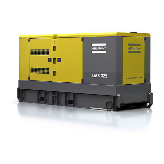
The QAS 275-325 Volvo is an AC generator, built for continuous running at sites where no electricity is available or as stand-by in cases of interruption of the mains. The generator operates at 50 Hz, 400 V - 3 phase, 50 Hz, 230 V - 3 phase and 60 Hz, 480 V - 3 phase. The QAS 275-325 Volvo generator is driven by a water-cooled diesel engine, manufactured by VOLVO PENTA. - Page 14 Alternator Air filter Coupling Drain flexible engine oil Drain flexible cooling water Engine Filler cap engine oil Filler cap cooling water Fuel filter Battery Oil drain pump Oil filter Engine oil level dipstick Battery switch - 14 -...
-
Page 15: Bodywork
The earthing rod, connected to the generator’s earth Bodywork Indicates that the generator may be terminal is located at the bottom of the frame on the The alternator, the engine, the cooling system, etc. are refuelled with diesel fuel only. outside. -
Page 16: Drain Plugs And Filler Caps
External fuel tank connection Control and indicator panel Qc1002™ The external fuel tank connection allows to bypass Indicates the 3-way valve. the internal fuel tank and to connect an external fuel General description Qc1002™ control tank to the unit. panel Make sure to connect the fuel supply line as well as XXXXXXXXXXXXXXX Indicates the partnumbers of... - Page 17 Qc1002™ Module Pushbutton and LED functions S2 ..Emergency stop button Push the button to stop the generator in case Following pushbuttons are used on of an emergency. When the button is the Qc1002™ pressed, it must be unlocked, before the generator can be restarted.
- Page 18 Following LEDs are used on the Qc1002™ Menu Overview Qc1002™ At Qc1002™, the LCD will show following START: Is used to start the unit in information: Manual Mode. – in Normal condition (scroll through the Power information using UP and DOWN): Qc1002 CAN STOP: Is used to stop the unit in Alarm...
- Page 19 Controller type and version display Alarm list display Service timer 1 & Service timer 2 display Qc1002 CAN Alarm List Service 1 v1.00.0 0 Alarm(s) Service 2 This view shows the controller type and the ASW This view shows the number of active alarms and version number.
- Page 20 Coolant temperature display Fuel level display Qc1002™ Menu Description Status Display (pop-up window) Water 62˚C Fuel 00168.1h 00168.1h This view shows the Coolant temperature and the This view shows the Fuel level and the running hours. running hours. In case special statuses are entered, a pop-up window Voltage - frequency - running hours See also “Parameter list”...
- Page 21 Icons is the default factory set language, but 6 not lowered. other languages can be selected: English, French, – Unit Type German, Italian, Spanish and Cyrillic (Russian). All information in the Parameter List display is always in English. Unit type 2 for QAS 275-325 Volvo! - 21 -...
- Page 22 This is the described menu flow for changing the unit type: Qc1002 CAN Qc1002 CAN Parameter Running time Unit type Unit type Unit type - 22 -...
- Page 23 Alarm Display (pop-up window) Following general groups of Alarms exist: – Warning: Alarm LED lights up + Alarm pop-up LOW FUEL LEVEL appears on the display + Alarm relay is empowered (if configured) – Trip of GB: ‘Warning’ actions + Generator Contactor opens LOW COOLANT –...
- Page 24 Displaying the engine DM1 alarm SPN98 "OIL LEVEL" Besides some engine specific alarms shown in the oil level SERVICE TIMER 1 standard alarm list, also all Diagnostic messages SPN99 "OIL FILTER DIFF P" DM1 (active alarms) can be shown on the display. pressure difference over oil filter Use the UP or DOWN buttons until DM1 is shown on SPN100...
- Page 25 LOG list Remote start operation SPN190 "SPEED" The unit will keep an event log of the latest 30 events. Installation wirings: speed FMI00 "HIGH LEVEL SHUTDOWN" Events are: – X25.1 & X25.2 to be wired for the remote start high level shutdown switch.
-
Page 26: Control And Indicator Panel Qc2002
Qc2002™ Module S2 ..Emergency stop button Control and indicator panel Push the button to stop the generator in case Qc2002™ of an emergency. When the button is General description Qc2002™ control pressed, it must be unlocked, before the generator can be restarted. The emergency panel stop button can be secured in the locked X25 F10... - Page 27 Pushbutton and LED functions Following LEDs are used on the Qc2002™ START: Is used to start the unit in Following pushbuttons are used on manual operation. the Qc2002™ Power STOP: Is used to stop the unit in Qc2002 CAN Automatic Alarm ENTER: Is used to select and manual or automatic operation...
- Page 28 Qc2002™ Menu Overview – in Alarm condition (scroll through Mains Green LED indicates that it is information using UP and DOWN): contactor possible to close the Mains At Qc2002™, the LCD will show following • a list of all active Alarms Contactor (only in AMF mode), if information: the Generator contactor is open.
- Page 29 Parameter display LOG list display Battery voltage display Parameter LOG List Battery 25.2 V 00168.1h This view shows a number of Parameter settings and This view shows the alarm memory and gives access This view shows the Battery voltage and the running gives access to them.
- Page 30 Oil pressure display kWh counter display One line voltage - frequency - active power display 3.2bar 4860kWh G L1-L2 400V 00168.1h G f L1 50Hz 80kW This view shows the Oil pressure and the running This view shows the kWh counter. hours.
- Page 31 Phase voltages mains display Qc2002™ Menu Description Status Display (pop-up window) DIAGNOSTIC M L1-N 230V M L2-N 230V M L3-N 230V If a special status has elapsed, the active view will be This view shows the phase voltages of the mains (is entered again automatically.
- Page 32 Automatic Mains Failure (AMF) operation Running hours adjust Menu's shown on the Parameter list LCD: – This application is only possible in combination Genset mode with the Auto mode. If the Manual Operation Running Time mode is selected the AMF operation will NOT Genset Mode function ! Cur.
- Page 33 Diagnostic menu Language selection MF high frequency Diagnostics Language MF high freq English 100% 120% This menu is used to power up the engine electronics Icons is the default factory set language, but 6 other This menu is used to set the maximum limit for the without starting the engine.
- Page 34 M frequency delay MF high voltage MF voltage delay MF volt delay M freq delay MF high volt 9900s 1.0s 990.0s 100% 120% This menu is used to set the delay, which defines how This menu is used to set the maximum limit for the This menu is used to set the delay, which defines how long the mains frequency has to be back within the mains voltage, in % of the nominal voltage (in AMF-...
- Page 35 Overvoltage delay Undervoltage delay Overfrequency delay > Volt Delay < Volt Delay > Freq Delay Overvoltage setpoint Undervoltage setpoint Overfrequency setpoint > Volt < Volt > Freq Undervoltage enable Overfrequency enable Underfrequency enable < Volt enable > Freq enable < Freq enable Enable enable...
- Page 36 Alarm Display (pop-up window) Underfrequency delay Following general groups of Alarms exist: – Warning: Alarm LED lights up + Alarm pop-up appears on the display + Alarm relay is < Freq Delay empowered (if configured) – Trip of GB: ‘Warning’ actions + Generator Contactor opens –...
- Page 37 LOW FUEL LEVEL SERVICE TIMER 1 HZ/V FAILURE LOW COOLANT SERVICE TIMER 2 OIL LEVEL LEVEL GENERATOR ENGINE ALARM OVERVOLTAGE TEMPERATURE GENERATOR EMERGENCY UNDER- STOP VOLTAGE GENERATOR OVER- START FAILURE FREQUENCY GENERATOR UNDER- STOP FAILURE FREQUENCY - 37 -...
- Page 38 Displaying the engine DM1 alarm SPN98 "OIL LEVEL" SPN190 "SPEED" Besides some engine specific alarms shown in the oil level speed standard alarm list, also all Diagnostic messages SPN99 "OIL FILTER DIFF P" FMI00 "HIGH LEVEL SHUTDOWN" DM1 (active alarms) can be shown on the display. pressure difference over oil filter high level shutdown Use the UP or DOWN button until DM1 is shown on...
-
Page 39: Control And Indicator Panel Qc4002
LOG list Fail classes Control and indicator panel The unit will keep an event log of the latest 30 events. All the activated alarms of the Qc2002™ have their Qc4002™ own pre-defined fail class. Events are: General description Qc4002™ control All alarms are enabled according to one of these three –... - Page 40 Qc4002™ module S2 ..Emergency stop button X25 ..Connection block Push the button to stop the generator in case Inside cubicle. Allows customer of an emergency. When the button is connections. pressed, it must be unlocked, before the generator can be restarted. The emergency Refer to circuit diagram for the stop button can be secured in the locked correct connection.
- Page 41 Pushbutton and LED functions UP: Increases the value of the MB: Manual activation of selected set point (in the setup menu). close breaker and open Following pushbuttons are used on In the daily use display, this button breaker sequence if SEMI- the Qc4002™...
- Page 42 Following LEDs are used on the The main Qc4002™ control unit (GB) ON LED green light indicates that the Qc4002™ includes 5 LEDs generator breaker is closed. LED yellow light indicates that the generator breaker has received a Qc4002 command to close on a black BUS, but the breaker is not yet closed due to interlocking of the GB.
-
Page 43: Setup Menu
Qc4002™ menu overview V2 view – The view shows some generator measurements. Main View – In the V1 view the user can scroll up and down to The display has 4 different lines. The information on 15 configurable screens showing different these lines can change, depending on which view is measurements of the generator, the bus and the used. - Page 44 If you select SETUP then you get the following view: Scrolling down will give all the protection The user can scroll to these choices and select one parameters: choice with the SEL button. After selection of SP the following view will be –...
- Page 45 – 9000 Software version – 9020 Service port – 911X User password Level 2 and Level 3 passwords can only be set through the Atlas Copco Utility Software PC Software. – 9120 Service menu – 9130 Single/Split/Three phase – 9140 Angle comp. BB/G Use the UP and DOWN buttons to change the settings and the SEL button to store the new setting.
- Page 46 This is the described menu flow: The menu flow is similar in the CONTROL SETUP, I/O SETUP and SYSTEM SETUP. For more details on the Setup menu we refer to the Qc4002™ User Manual. - 46 -...
- Page 47 MB Trip. Changing parameters Consult the Qc4002™ user manual for all customer level parameters, which can be accessed using password "2003". In order to receive the default parameters for your unit, please contact Atlas Copco Service staff. - 47 -...
- Page 48 Standard modes Semi-Auto mode Block mode The unit has four different running modes and one In semi-auto mode the operator has to initiate all When the block mode is selected, the unit is locked block mode. The required mode can be selected via sequences.
- Page 49 Diagnostics menu Standard applications Island operation This diagnostics menu can be entered via channel In the Qc4002™ module 9 application types can be This application is possible in combination with 6700. This menu is used for engine diagnostics selected. A combination of each application type with SEMI-AUTO mode or AUTO mode.
- Page 50 Automatic Mains Failure (AMF) Installation wirings – Mains breaker control lines have to be wired to operation X25.13/X25.14/X25.15/X25.16. These terminals – The link between X25.10/X25.11 has to be are voltage free contacts. The power for the MB removed. This application is only possible in combination with has to be supplied by the customer (24 Vdc/ the AUTO mode.
- Page 51 Fixed Power (FP) operation Load Take Over (LTO) operation – Make sure the connections between X25.33 & X25.3; X25.34 & X25.4; X25.35 & X25.5; This application is possible in combination with This application is normally used in combination with X25.36 & X25.6 are removed. SEMI-AUTO mode or AUTO mode.
- Page 52 Multiple gen-sets with power – Mains breaker control lines have to be wired to Installations are possible with stand-alone generators X25.13/X25.14/X25.15/X25.16. These terminals management (PMS) or with the Mains (extra Qc4002™ Mains is then are voltage free contacts. The power for the MB needed).
- Page 53 Paralleling The start signal is the value of the maximum required The priority on starting & stopping the generators can load step. be chosen on priority settings or on the amount of Prior to starting parallel operation of two generators, running hours.
- Page 54 Only with Power Transducer (*) (*) A Power Transducer is a device that measures the actual power of the mains and which translates this into a 4...20 mA signal towards the Qc4002™ module. For details, please contact Atlas Copco. - 54 -...
- Page 55 The installation can contain up to 16 Qc4002™ modules. If the Mains is included in the installation, then an extra Qc4002™ module is required. The installation can be monitored and controlled via the PMS Software Package. For details on this application, please contact Atlas Copco. - 55 -...
- Page 56 Do not put this value above 60 seconds to avoid any possible damage. 4. For more information on the Qc4002™ module and its applications, we refer to the Qc4002™ User manual. If you need more assistance, please contact Atlas Copco. - 56 -...
-
Page 57: Output Terminal Board
N13 ..Earth leakage relay X1 ..Main power supply Output terminal board Detects and indicates an earth fault current Terminals L1, L2, L3, N (= neutral) and PE The cubicle provides a terminal board for easier and activates the main circuit breaker Q1. (= earthing), behind a small transparent connection of cables. -
Page 58: Dual Frequency
Dual frequency Battery switch Dual frequency allows the unit to work at 50 Hz or at The battery switch is situated inside the sound- 60 Hz with an accuracy of constant load. The insulated bodywork. It allows to open or to close the frequency selection is done by means of switch S11. -
Page 59: Operating Instructions
Check for sufficient ventilation so that the installation must directly cooling air is not recirculated. If necessary, connected to the functional earth. consult Atlas Copco. - 59 -... -
Page 60: Connecting The Generator
X- those proposed below. ray equipment, audio amplifiers and elevators. X = Reactance (/km to VDE 0102) Consult Atlas Copco for measures against the adverse Wire section Max. current (A) Connecting the load influence of non-linear loads. -
Page 61: Before Starting
Protection Before starting Operating Qc1002™ For safety reasons, it is necessary to – With the generator standing level, check the Starting Qc1002™ provide an isolating switch or circuit engine oil level and top up if necessary. The oil breaker in each load circuit. Local level must be near to, but not exceed the high mark To start up the unit locally, proceed legislation may impose the use of... -
Page 62: Operating Qc2002
– Put the remote start/stop switch in position start. – Put the starter switch S20 in position O (OFF) to The generator’s doors may only shut down the voltage apply towards the – The unit starts a preheating cycle which takes 12 remain opened for short periods Qc1002™... - Page 63 To start up the unit from a remote To stop the unit when the Qc2002™ – Check, by means of the generator gauges, that the location, proceed as follows: module is in AUTOMATIC operation voltage between the phases is identical and that the rated current in the third phase (L3) is not mode, proceed as follows: –...
-
Page 64: Operating Qc4002
During operation Qc4002™ Stopping Qc4002™ Operating Qc4002™ Following points should be carried out regularly: – When in SEMI-AUTO mode, use the STOP Starting Qc4002™ button to stop the generator. The GB button will – Check the display for normal readings. work to open the GB. -
Page 65: Maintenance
2912 4509 05 For the most important subassemblies, Atlas Copco has developed service kits that combine all wear parts. These service kits offer you the benefits of genuine parts, save on administration costs and are offered at reduced price, compared to the loose components. Refer to the parts list for more information on the contents of the service kits. - Page 66 At least once a month the engine should run for one hour. If possible a Inspection by Atlas Copco Service technician high load (> 30%) should be applied so that the engine reaches its operating temperature.
-
Page 67: Engine Maintenance
Refer to the engine’s operator manual for full It is strongly recommended to use do not apply. Check and/or replace filters and clean maintenance schedule. Atlas Copco branded lubrication oils. radiator on a regular basis. (*) Measuring the alternator High-quality, mineral, hydraulic or synthesized... -
Page 68: Engine Oil Level Check
Engine oil level check EURO -3 & -2, EPA TIER II & III engines running on PAROIL from Atlas Copco is the ONLY oil tested Consult the Engine Operation Manual for the oil low sulphur diesel for lower oil and fuel consumption. -
Page 69: Engine Coolant Specifications
0.175 1604 5308 00 currently in use in Atlas Copco compressors and personal injury from the splash of hot generators. coolant. 1604 5307 01... -
Page 70: Coolant Check
Flush parameters. high engine operating temperatures. – Flush twice with clean water. Used coolant must – A refractometer can be ordered from Atlas Copco Visual check be disposed or recycled in accordance with laws with part number 2913 0028 00. -
Page 71: Storage Of The Generator
Storage of the generator Preparing for operation after storage Storage Before operating the generator again, remove the – Store the generator in a dry, frost-free room which wrapping, VCI paper and silica gel bags and check the is well ventilated. generator thoroughly (go through the checklist “Before starting”... -
Page 72: Checks And Trouble Shooting
Checks and trouble shooting Checking voltmeter P4 – Put a voltmeter in parallel with voltmeter P4 on Never perform a test run with the control panel. connected power cables. Never touch an electrical connector without a – Check that the read-out of both voltmeters is the voltage check. -
Page 73: Alternator Troubleshooting
Alternator troubleshooting Symptom Possible cause Corrective action Alternator gives 0 Volt Blown fuse. Replace fuse. Excite the alternator by applying a 12V battery voltage with a 30 No residual voltage. resistor in series on the + and - terminals of the electronic regulator, respecting the polarities. -
Page 74: Volvo Units
The engine control circuit diagrams and the power xxxxxxxx – Outlet sockets (S) -power in control circuit diagrams for the standard QAS 275-325 Volvo units, for the units with options and for the units with – Dual voltage (2V) xxxx xxxx xxxxxx... - Page 75 Outlet sockets (S) Q2 ..Circuit breaker for X2 Q6 ..Circuit breaker for X6 Interrupts the power supply to X2 when a A brief description of all outlet sockets and circuit Interrupts the power supply to X6 when a short-circuit occurs at the load side, or when short-circuit occurs at the load side, or when breakers provided on the generator is given hereafter:...
- Page 76 Dual voltage (2V) X4 ..3-phase outlet socket Q1.1 ..Circuit breaker for low voltage, high current Provides phase L1, L2, L3, neutral and The generator can run in two different modes: earthing. Interrupts the low voltage power supply towards X1 when a short-circuit occurs at 3 phase, lower voltage X5 ..
- Page 77 EDF-unit or vice Consult the Cosmos manual for a descprition of LED versa has to be carried out by a indications. qualified person from “Electricité de For information about COSMOS™, consult your France”. local Atlas Copco dealer. - 77 -...
-
Page 78: Overview Of The Mechanical Options
Make sure that: Overview of the mechanical options – the big size coupling is used for the inlet. The following mechanical options are available: – the small size coupling is used for the outlet. – Quick couplings An extra clamp needs to be used to guide the fuellines. -
Page 79: Technical Specifications
Technical specifications Technical specifications for QAS 275 units Readings on gauges Gauge Reading Unit Ammeter L1-L3 (P1-P3) Below max. rating Voltmeter (P4) Below max. rating Settings of switches Switch Function Activates at Engine oil pressure Shut down 0.5 bar Engine coolant temperature Shut down 103°C Specifications of the engine/alternator/unit... - Page 80 Rated apparent power (PRP) 3ph 275 kVA 285 kVA Rated apparent power (PRP) 3ph, lower voltage (optional) 275 kVA Rated voltage 3ph line to line 400 V 480 V Rated voltage 3ph line to line lower voltage (optional) 230 V Rated current 3ph 397 A 343 A...
- Page 81 Status of neutral earthed earthed Alternator Standard IEC34-1 IEC34-1 ISO 8528-3 ISO 8528-3 Make LEROY SOMER LEROY SOMER Model LSA 46.2 L9 LSA 46.2 L9 Rated output, class H temperature rise 280 kVA 344 kVA rating type acc. ISO 8528-3 “BR”...
- Page 82 Circuit-breaker, 3ph., lower voltage (optional) Number of poles Thermal release It (thermal release is higher at 25°C) 690 A Magnetic release Im 4 x In Fault current protection Residual current release IDn 0.030-30 A 0.030-30 A Insulation resistance 10-100 kOhm 10-100 kOhm Outlet sockets (optional) domestic (1x)
- Page 83 Specific mass fuel used: 0.86 kg/l. Derating table (in %, 100% is declarated power at “Performance data”) Temperature Height (°C) 1000 1500 2000 2500 3000 3500 4000 For use of generator outside these conditions, please contact Atlas Copco. - 83 -...
-
Page 84: Technical Specifications For Qas 325 Units
Technical specifications for QAS 325 units Readings on gauges Gauge Reading Unit Ammeter L1-L3 (P1-P3) Below max. rating Voltmeter (P4) Below max. rating Settings of switches Switch Function Activates at Engine oil pressure Shut down 0.5 bar Engine coolant temperature Shut down 103°C Specifications of the engine/alternator/unit... - Page 85 Rated voltage 3ph line to line 400 V 480 V Rated voltage 3ph line to line lower voltage (optional) 230 V Rated current 3ph 469 A 415 A Rated current 3ph lower voltage (optional) 816 A Performance class (acc.ISO 8528-5:1993) Single step load acceptance (0-PRP) 143 kW 207 kW...
- Page 86 Status of neutral earthed earthed Alternator Standard IEC34-1 IEC34-1 ISO 8528-3 ISO 8528-3 Make LEROY SOMER LEROY SOMER Model LSA 46.2 VL 13 LSA 46.2 VL 13 Rated output, class H temperature rise 325 kVA 381 kVA rating type acc. ISO 8528-3 “BR”...
- Page 87 Circuit-breaker, 3ph., lower voltage (optional) Number of poles Thermal release It (thermal release is higher at 25°C) 800 A Magnetic release Im 4 x In Fault current protection Residual current release IDn 0.030-30 A 0.030-30 A Insulation resistance 10-100 kOhm 10-100 kOhm Outlet sockets (optional) domestic (1x)
- Page 88 Specific mass fuel used: 0.86 kg/l. Derating table (in %, 100% is declarated power at “Performance data”) Temperature Height (°C) 1000 1500 2000 2500 3000 3500 4000 For use of generator outside these conditions, please contact Atlas Copco. - 88 -...
-
Page 89: Conversion List Of Si Units Into British Units
Conversion list of SI units into Dataplate British units Maximum permitted total weight of the vehicle Maximum permitted front axle load Maximum permitted rear axle load 1 bar 14.504 psi Company code 0.035 oz Product code 1 kg 2.205 lbs Unit serial number 1 km/h 0.621 mile/h... -
Page 90: Disposal
Your Atlas Copco generator consists for the most part Remove the batteries. Do not throw batteries into the of metallic materials, that can be remelted in fire (explosion risk) or into the residual waste. - Page 91 Circuit diagrams - 91 -...
- Page 92 9822 0993 25/03 Applicable for QAS 275-325 - Qc1002™, Engine Circuit X9 X9 S11d ded. 60Hz 12 13 17 18 33 34 to Control Module A1 Qc1002 canbus Sx=Remote Start/Stop-switch max. 24Vdc, 4A 11 12 8 Plant Contactor Output: 24Vdc, max.
- Page 93 F G H Cubicle Canopy Position of Relay Cont. Terminal strip X11 Note with X11 S11 a Legend Connect wires Wire size : Colour code : ..b only if S11 is required aa = 0.5mm 0 = black a3 a3 a = 1 mm 1 = brown connect wire 35...
- Page 94 Control module (configure in UNIT-type 2) Fuel level sensor Fuse Battery 24V Panel light Aux.relay for Y7 (O) Engine control relay Starter motor P1-3 A-meters V-meter Resistor 120 ohm Battery switch Emergency stop button (S2b: see Power Circuit) Water in fuel switch (O) Voltmeter change-over switch S11d Selector switch 50/60Hz...
- Page 95 - 95 -...
- Page 96 9822 0993 26/03 Applicable for QAS 275-325 - Qc2002™, Engine Circuit towards to Circ.Diagr POWER X25.8 X9.441 & X9.442 b6 b0 a0 a0 a0 a0 a0 a6 a2 26 27 37 38 53 54 57 58 Fx Fx Fx Fx...
- Page 97 Terminal strip X11 Legend Wire size : Colour code : S11 a Note with X11 a = 1 mm 0 = black b = 1.5mm 1 = brown Connect wires ..b only if S11 c = 2.5mm 2 = red is required d = 4 mm 3 = orange...
- Page 98 Generator control unit Fuel level sensor Fuse 10A DC Fuse 15A DC (O) Battery 24Vdc Panel light Aux.relay for Y7 (O) Engine control relay Starter motor Eberspacher fuel pump (O) Eberspacher timer (O) Eberspacher (O) P1-3 A-meters V-meter Resistor 120 ohm Resistor 470 ohm 7W (O) Battery switch Emergency stop...
- Page 99 - 99 -...
- Page 100 9822 0993 28/05 Applicable for QAS 275-325 - Qc4002™, Engine & Power Circuit Note "M": Remove link "M" when Note: Connect R9 between parallelling with the mains. In X32.1/X32.3 at the start and AMF-mode or in case of between X32.4/X32.6 at the mainsparallelling, the end of data loop.
- Page 101 A B C D R S T d2(+) Qc4002 Display P1(C) RESE T AOP-1 P2(F) d1(-) CAN1 CAN2 X10 X10 30mA Legend S11b Wire size : Colour code : a = 1 mm² 0 = black Position of Relay Contacts Terminal strip X 1 1 b = 1.5 mm²...
- Page 102 Terminal board Generator control unit Socket outlet (16A-1phase) LCD display Terminal strip Fuel level sensor Connector wire harness F1-6 Fuse 250mA Terminal strip Fuse 10A DC Customer's terminal strip Battery 24Vdc PMS interface terminals Alternator Air inlet shutdown valve (O) Fuel solenoid relay Optional equipment Aux.relay for Y7 (O)
- Page 103 - 103 -...
- Page 104 9822 0993 30/04 Applicable for QAS 275-325 - Qc1002™, Qc2002™, Power Circuit T1-3 P1-3 Wire size (O) QAS500 (O) QAS275-QAS325 QAS275 400A 400/5A 0-400A QAS325 470A 600/5A 0-600A QAS500 720A 800/5A 0-800A 2x lx 400V/480V 400V/480V Breaker Set. Frequency Selection...
- Page 105 Cubicle Canopy (O) 1-Phase Socket See Circ.Diagr Engine See Circ.Diagr Engine S11b (O) 3-Phase Sockets hx54 30mA 125A 125A PE-EDF See Note 2 (O) N-EDF - 105 -...
- Page 106 F1-3 Fuse 4A Alternator Automatic voltage regulator Earth leakage relay Main circuit breaker Circuit breaker (16A+30mA) Circuit breaker (125A - 3ph) Circuit breaker (63A - 3ph) Circuit breaker (32A - 3ph) Circuit breaker (16A - 3ph) Coolant heater Voltage adjustment potmeter (1kOhm) Emergency stop (S2a see Engine Circuit) S11a,b...
- Page 107 - 107 -...
- Page 108 9822 0993 31/01 Applicable for QAS 275-325 - Dual voltage Legend Wire size : Colour code : aa = 0.5 mm² 0 = black 1 mm² 1 = brown 400Vy/230Vd = 1.5 mm² 2 = red = 2.5 mm² 3 = orange S10a 4 mm²...
- Page 109 Notes See Note 1 Note 1: The PE-N connection has to be made at the alternator-side of main Circuit Breaker Q1. See Circ.Diagr Engine S10b S10c Cubicle Canopy Q1.1 See Circ.Diagr Engine Q1.2 See Circ.Diagr Engine Q1.1 Q1.2 T1-3 P1-3 Wire size QAS 275 690A...
- Page 110 F1-3 Fuse 4A Alternator Automatic voltage regulator Earth leakage relay Q1.1 Circuit breaker (lower voltage) Q1.2 Circuit breaker (higher voltage) Coolant heater Voltage adjustment potentiometer Emergency stop (S2a see engine circuit diagram) S10abc Supply voltage switch (S10d see engine circuit diagram) Earth relay lock-out switch T1-3 Current transformers...
- Page 111 Following documents are provided with this unit: – Test Certificate – EC Declaration of Conformity: EC DECLARATION OF CONFORMITY We, Atlas Copco Airpower n.v., declare under our sole responsibility, that the product Machine name : Power generator (< 400 kW) Commercial name : Serial number Which falls under the provisions of article 12.2 of the EC Directive 2006/42/EC on the approximation of the...
- Page 112 - 112 -...
- Page 114 www.atlascopco.com...
Need help?
Do you have a question about the QAS 275-325 and is the answer not in the manual?
Questions and answers