
Subscribe to Our Youtube Channel
Related Manuals for Omtech PRONTO 40


Summary of Contents for Omtech PRONTO 40
- Page 1 V20240715 PRONTO 40/60 Cabinet Laser Engraver User Manual Read Carefully Before Use Keep for Future Reference...
- Page 3 Contact Us Come join the omtech community at our official laser group on Facebook or visit the company forums at omtechlaser.com. Check our YouTube channel for helpful hints and instructional videos.
-
Page 4: Table Of Contents
Contents 1. Safety Information .................... 1 Disclaimer ..............................1 Designated Use ............................1 Symbol Guide ............................. 2 1.4 General Safety Instructions ........................3 Laser Safety Instructions ......................... 6 1.6 Electrical Safety Instructions ........................7 Material Safety Instructions ........................8 2. Introduction ......................11 General Information .......................... - Page 5 5.2.2 Powering on ........................... 42 5.2.3 Preparing Material ........................42 5.2.4 Preparing the Engraving Pattern ..................... 43 5.2.5 Autofocusing ..........................44 5.3 Engraving Proper ............................45 5.4 Wrapping-up ............................... 45 5.5 Rotary Operation (Optional) ........................46 5.5.1 Installing a Rotary Attachment ....................46 5.5.2 Engraving Procedures with a Rotary Attachment ...............
- Page 6 Contents 6.18 Reading USB Files............................62 6.19 System Memory Management ....................... 62 7. Maintenance ....................... 63 Maintenance Overview ..........................63 7.2 Cleaning ................................ 64 7.2.1 Cleaning the Main Bay and Engraver ..................64 7.2.2 Cleaning the Water System ....................... 65 7.2.3 Cleaning the Focus Lens ......................
- Page 7 BEAMING WITH POSSIBILITIES!
-
Page 8: Safety Information
1. Safety Information 1.1 Disclaimer This manual is the designated user guide for the installation, setup, safe operation, and maintenance of your cabinet laser engraver. ALL personnel involved in the installation, setup, operation, maintenance, and repair of this machine should read and understand this manual, particularly its safety instructions. Some components are extremely high voltage and/or produce powerful laser radiation. -
Page 9: Symbol Guide
1.3 Symbol Guide The following symbols are used on this machine’s labeling or in this manual: These items present a risk of serious property damage or personal injury. These items address similarly serious concerns about the laser beam. These items address similarly serious concerns about electrical components. These items address similarly serious concerns about fire hazards. -
Page 10: General Safety Instructions
1. Safety Information 1.4 General Safety Instructions • Your device should come with instruction labels in the following locations:... - Page 11 If any of these symbols is missing, illegible, or becomes damaged, it must be replaced. • ALWAYS follow federal, state, and local laws, codes, and regulations concerning the use of laser marking machinery. • ALWAYS use this machine in accordance with this manual and the manual for the engraving software included with it.
- Page 12 1. Safety Information • Any untrained personnel who might be near the machine while it is in operation MUST be informed that it is dangerous and be fully instructed on how to avoid injury during its use. • ONLY use this product for its intended purpose, engraving signs and logos on consumer products or applicable substrates.
-
Page 13: Laser Safety Instructions
• Ensure that the local fire department’s phone number is displayed nearby. • In the case of a fire, cut electrical power before dousing the flame. Familiarize yourself with the correct range for your extinguisher before use. Take care not to use your extinguisher too close to the flame, as its high pressure can produce blowback. -
Page 14: Electrical Safety Instructions
1. Safety Information • NEVER attempt to view the laser directly without protective eyewear. ALWAYS wear safety goggles or glasses designed to filter the specific wavelength of your engraver’s laser with an optical density (OD) of 5+. As even seemingly matte materials can produce harmful reflected beams, care should be taken to keep anyone without protective eyewear from observing the machine during operation. -
Page 15: Material Safety Instructions
• ONLY turn on the power to this machine when it is well grounded, either via a firm connection to a 3-prong outlet or via a dedicated grounding cable firmly connected to the proper slot on the back of the control cabinet. Do not use with an ungrounded 3-to-2 prong adapter. - Page 16 1. Safety Information • Users of this marking machine are responsible for confirming that materials to be processed can withstand the heat of a CLASS 4 laser and will not produce any emissions or byproducts either harmful to people nearby or in violation of any local or national laws or regulations. •...
- Page 17 • This machine CANNOT be used with THE FOLLOWING MATERIALS OR WITH ANY MATERIALS WHICH INCLUDE THEM: Artificial Leather containing Hexavalent Chromium (Cr[VI]), due to its toxic fumes Astatine, due to its toxic fumes Beryllium Oxide, due to its toxic fumes ...
-
Page 18: Introduction
2. Introduction 2.1 General Information Your laser engraver works by emitting a powerful laser beam from a glass tube filled with excited carbon dioxide (CO ₂ ), catalyzing nitrogen (N ₂ ), and insulating helium (He), reflecting that beam off three mirrors and through a focus lens, and using this focused light to cut and etch designs into certain substrates. -
Page 19: Technical Specifications
2.2 Technical Specifications Model PRONTO 40 PRONTO 60 Input Power AC 110–120 (V) 60 Hz Power Consumption 1100 W Rated Power 80 W 130 W Expected Service Life 12000/10000/8000 (hr.) at <40% / 40–70% / >70% Power Laser Wavelength 10640 nm Diameter 2.36 in. -
Page 20: Components
2. Introduction 2.3 Components 2.3.1 Package List... - Page 21 Item Qty. Exhaust Fan Exhaust Pipes, 150 mm Diameter and 1.5 m Long Power Cord USB Cable Ethernet Cable Pipe Clamps, 150 mm Diameter Laser Keys with A Focal Length Ruler Access Keys USB Flash Drive with Engraving Software Included Focus Lens Repair Tools A Set of Hex Wrenches Flat-head Screwdriver...
-
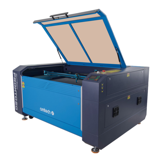
Page 22: Main Parts
2. Introduction 2.3.2 Main Parts Front Provides access to the main bay for placing and retrieving materials, Cover as well as fixing the laser path alignment and other maintenance. Power to the laser is automatically cut when the cover is opened. Protects you and others from the laser and its reflection, allowing monitoring of the engraving process. - Page 23 Supports the movement of the X-axis rail up and down across the Y-Axis Rail workbed. Laser Head Holds Mirror 3, the focus lens, and the air assist outlet. Can be adjusted in height to fit thinner and thicker materials, as well Workbed as adjusted between the aluminum and honeycomb platforms.
- Page 24 2. Introduction Right Left Back...
- Page 25 Top Right Access Provides access to the control panel, buttons, and sensors for Door maintenance at the front rear, and sides and repair. Includes the machine’s ports for its USB, computer, and Ethernet Connection Inputs connections. Right Bottom Provides access to the mainboard, motor drivers, and control power Access Door supply.
-
Page 26: Laser Head
2. Introduction 2.3.3 Laser Head Moves along the Y axis, with its movement controlled by limit X Axis Rail switches. Transfers the laser from Mirror 2 to the focus lens. Can adjust its 3rd Mirror angles. Focus Lens With a diameter of 20 mm, directs and focuses the laser beam to its point of contact with the engraving material. -
Page 27: Connection Inputs
2.3.4 Connection Inputs Back Right Allows you to load and save designs and parameters directly onto the USB Drive engraver. USB Cable Connects to your control computer and its engraving software. Ethernet Cable Connects to your control computer and its engraving software. Provides main power supply with the standard 3-prong main power Main Power Port cable. -
Page 28: Right Bottom Access Door
2. Introduction 2.3.5 Right Bottom Access Door Back Right PRONTO 40... - Page 29 PRONTO 60 Controls the engraving process, responding to commands from Mainboard your engraving software or the machine’s control panel. Y-Axis Driver Moves the X rail along the Y rail. X-Axis Driver Moves the laser head along the X rail. Control Power Supply Powers the machine’s control panel.
-
Page 30: Back Left Access Door (Laser Power Supply)
2. Introduction 2.3.6 Back Left Access Door (Laser Power Supply) Back Right... - Page 31 Connects to the laser tube’s anode or positive end, providing High-Voltage Wire high-voltage current to power the laser. Mounting Holes Allows simple installation and removal. Provides the real-time current value to the laser tube in Digital Display milliamps. Laser Indicator Light Illuminates when current is being sent to the laser tube.
-
Page 32: Control Panel
2. Introduction 2.3.7 Control Panel Front Right... - Page 33 Button Description Returns the machine to the saved default parameters. Manually fires the laser. Opens the file control menu. Sets the starting point for the laser head. Traces the outline of the current design for sizing. Opens the function menu. Moves the laser head along the X axis or the left/right cursor.
-
Page 34: Panel Screen
2. Introduction 2.3.8 Panel Screen... - Page 35 Traces the processed file image during file preview display and Graphic Display Area processing. Displays the file number, speed, and maximum power of the Parameter Display Area current processing file. C o o r d i n a t e D i s p l a y Displays the coordinate values of the current position of the laser Area head.
-
Page 36: Installation
3. Installation 3.1 Selecting a Location The location should meet all of the following requirements: • The location meets all of the requirements mentioned in on page § Safety Information • The location should be stable, level, dry, and climate-controlled to ensure an ambient temperature of 40 ℉... -
Page 37: Grounding The Machine
3.2 Grounding the Machine This machine employs a CLASS 4 laser which is extremely high voltage and potentially dangerous. Therefore, users MUST securely ground it to avoid the buildup of static electricity. Execute one of the following depending on your situation: If applicable, execute both grounding methods. -
Page 38: Installing The Machine
3. Installation 3.3 Installing the Machine Make sure that you understand all the instructions before installation to execute a proper setup and achieve safe laser performance. If you have any installation questions or problems, contact our technicians and customer support team. A complete working system consists of the laser engraving cabinet, an exhaust system, a water cooling system (not included), all applicable connection cables, and the laser and access keys. -
Page 39: Installing The Water Cooling System (Not Included)
3.3.2 Installing the Water Cooling System (Not Included) A water cooling system—typically a water pump or chiller—MUST be used with this engraver to absorb the heat produced by the laser tube. The water cooling system is essential to your engraver’s performance and longevity. Without a properly maintained cooling system, the glass laser tube WILL explode from excess heat. -
Page 40: Installing The Air Assist Pump
3. Installation 3.3.3 Installing the Air Assist Pump Connect the power cable of your air assist pump to the air assist pump port on the machine. 2. Connect your air assist outtake port on the air assist pump to the air assist intake port on the machine via a hose. -
Page 41: Installing The Exhaust System
3.3.4 Installing the Exhaust System An exhaust system—typically either an external vent or a dedicated air purifier—MUST be used to remove the dust and gases produced by the engraving process. Exhaust Fan Connect one of the provided exhaust pipes between the machine and the inlet port of the exhaust fan. -
Page 42: Connecting To Power Supply
3. Installation 3.3.5 Connecting to Power Supply Back Right • Use a dedicated circuit for the engraver. Make sure the circuit has an easily accessible circuit breaker. • The circuit MUST be 3-core, with each wire being at least 14 AWG. •... -
Page 43: Connecting To Your Control Computer
3.3.6 Connecting to Your Control Computer Back Right The control computer can be connected in any of the two ways: • Via the provided USB cable (via the port marked “USB Cable”). In this way, the control computer is directly connected to the engraver, so it should not be placed more than 15 feet (4.5 m) away in order to avoid possible interference to the signal on its line. -
Page 44: Initial Testing
4. Initial Testing You should start your machine and test the functions below before conducting ANY other work with your machine for safety. 4.1 Starting the Machine Make sure your water cooling system, air assist pump, and exhaust system have been installed. -
Page 45: Pre-Use Testing
4.2 Pre-use Testing Do the following tests to ensure your engraver is working properly. If any function is not working, the related part must be replaced or repaired before further use. Test Desired Location Test method Functions Effects The laser Follow the steps above to fire the laser. -
Page 46: Turning Off The Machine
4. Initial Testing Test Test method Desired Effects Functions Attach a piece of masking tape around A tiny hole has formed at the the laser aperture, pressing so that a perfect center of the circular circular mark is left on the tape. Calibrate mark. -
Page 47: Typical Operation Sequence
5. Typical Operation Sequence 5.1 Operation Overview Operate this laser engraver only in accordance with all the instructions provided in this manual. Failure to follow the guidelines detailed here can result in property damage and personal injury. The engraver is operable either through: •... -
Page 48: Pre-Operation Preparation
5. Typical Operation Sequence 5.2 Pre-Operation Preparation 5.2.1 Checking Make sure the power supply is ok. 2. Ensure proper ventilation. a. Turn on the exhaust system and check its functionality. b. Make sure that any back-up ventilation systems are in place and running smoothly. NEVER operate the laser if the fan and pipes are not working to purify or remove the fumes produced by the target material. -
Page 49: Preparing Material
5.2.3 Preparing Material Open the engraver’s cover. 2. Place a sample piece of your material on the workbed. The default location of the laser head’s zero position is at the top left corner of the workbed. This can be changed by moving either your design or the engraver’s origin position using the control panel or your engraving software. -
Page 50: Preparing The Engraving Pattern
Conversion Chart for Power Power 100% Current (mA) for PRONTO 40 Current (mA) for PRONTO 60 The threshold for the lowest setting is 10%. The laser will not fire at any setting lower than this. It is NOT recommended to use the laser tube at full capacity, especially for extended periods. -
Page 51: Autofocusing
5.2.5 Autofocusing Move your laser head to the original place, the top left corner of the workbed. 2. Place your sample material close to the autofocus sensor to the right. Autofocus Sensor Sample 3. Lower the workbed until it is lower than the sensor. 4. -
Page 52: Engraving Proper
5. Typical Operation Sequence 5.3 Engraving Proper Press to engrave your design. Again, do not stare continuously at the laser even through the protective polycarbonate window. Watch for possible issues like sparks or fires, however, and be prepared to quickly extinguish a fire if necessary. -
Page 53: Rotary Operation (Optional)
5.5 Rotary Operation (Optional) 5.5.1 Installing a Rotary Attachment Remove the steel saw bed or the aluminum knife bed and the support bar of the blade. 2. Place your rotary axis in an open area. 3. Put the material and adjust the position using the rotary axis’ knobs. 4. -
Page 54: Engraving Procedures Proper
5. Typical Operation Sequence 5.5.3 Engraving Procedures Proper Prepare your engraved material per § 5.2. Pre-Operation Preparation on page 41. 2. Focus the laser. 3. Turn on the switch of your rotary attachment. The rotation of the rotary attachment will be controlled by the engraver’s Y axis settings. -
Page 55: Glass
5.6.2 Glass When engraving glass, generally use high power and low speed. As with ceramics, it can be helpful to run more loops at lower settings to avoid cracks. Care must be taken when engraving fiberglass and carbon fiber to avoid combinations of settings that produce a laser intensity great enough to damage the structural integrity of its component fibers, producing blurry marking. -
Page 56: Plastics
5. Typical Operation Sequence 5.6.6 Plastics Plastics for engraving are available in many different colors and thicknesses and with many different coatings and surfaces. The majority of available plastics can be well engraved and cut with the laser. Plastics with a microporous surface seem to give the best result, because less surface material needs to be removed. -
Page 57: Wood
5.6.10 Wood As with rubber, there is a huge variety of woods and testing your specific material is essential to get the best results. In general, wood with consistent grain and coloring engraves more evenly. Knotted wood produces uneven effects, while resinous wood produces greater edge contrast. Some soft woods like balsa, cork, and pine engrave well (albeit with low contrast) at low or moderate power settings and high speed. -
Page 58: Control Panel Instructions
6. Control Panel Instructions 6.1 Overview You can control your engraver directly from the built-in control panel, through a direct connection with your computer, or over the internet. For details on operating your engraving software, see its separate manual. The built-in control panel can operate the laser manually or engrave designs loaded onto flash drives and external hard drives connected to the USB port on the right side of the cabinet. - Page 59 When running a design from the control console, this will be the main display. The design should appear in the top left corner and its name and the current speed and power settings on the top right. The position of the laser head relative to the workbed appears as the X (horizontal) and Y (vertical) coordinates.
-
Page 60: Laser Power
6. Control Panel Instructions 6.2 Setting the Laser Power Select Max-Power or Min-Power on the main interface, and the following displays will appear. When is pushed, the green block can move up and down to denote the changing item. Then can be used to change the value. -
Page 61: Function Menu
6.4 Function Menu Press on the main interface to enter the Function interface, as shown below: Push to select an item, and then push to enter the corresponding submenu. 6.5 Adjusting the Z Axis When Z Move is selected, push to control the movement of the Z axis when a motorized workbed (sold separately) is installed. -
Page 62: Resetting The Axes
6. Control Panel Instructions 6.7 Resetting the Axes When Axis Reset+ is selected, push and the display will show: Push to select an item. Press to start the resetting of the selected axis, and the message “Resetting Is Underway” will show on the screen. -
Page 63: Laser Pulse Mode
6.9 Adjusting the Laser Pulse Mode When Laser Set+ is selected, press and the display will show: The operation method is the same as the previous setting. When Continue is selected, press to fire the laser, and release the key to finish firing. - Page 64 6. Control Panel Instructions Details of each item are shown below: • Multiple Origins Enable: Yes or No can be selected. If you select No, the system will use single- origin settings. You can press and set the origin. If you select Yes, the system will use the multiple-origin settings and on the keyboard becomes invalid.
-
Page 65: Setting Default Parameters
6.11 Setting Default Parameters When Set Fact. Para. is selected, the following interface will be displayed: Push to select a password and press to save it. The current parameters of the machine will be stored as its defaults. They can then be retrieved by using the Restore Default Parameters command. -
Page 66: Ip Address
6. Control Panel Instructions 6.14 Setting the Machine’s IP Address When IP Setup+ is selected, press and the display will show: IP address: Gatewaya ddress: Press to select an item, and push to change the parameters. The default address of the engraver is 192.168.1.100. If this is already in use on your local network, use 192.168.1 for the first three sections and choose a unique value for the last section. -
Page 67: Screen Reference
6.16 Setting the Screen Reference When Screen Origin is selected, press and the display will show: This interface sets the relative position of the origin. Different origin positions can generate different reflections of the graph over the X/Y axis. The operation method is the same as those described above. -
Page 68: File Management
6. Control Panel Instructions 6.17 File Management Select on the main interface, and the following dialogue box will appear: The system will automatically read the memory files. The file name and the work times will be listed and the selected file will be previewed in the upper right corner. Different memory files can be selected by using . -
Page 69: Reading Usb Files
6.18 Reading USB Files If Udisk+ is pressed, the display will show: • Read Udisk: Reads the file list in the inserted USB drive. • Copy to Memory: Copies the target file to the system. • Delete: Deletes the selected file from the USB drive. -
Page 70: Maintenance
7.Maintenance 7.1 Maintenance Overview • The use of procedures other than those specified herein may result in hazardous laser radiation exposure. • Before any cleaning or maintenance work, always switch off the device and disconnect it from its power supply. •... -
Page 71: Cleaning
7.2 Cleaning 7.2.1 Cleaning the Main Bay and Engraver Cleaning Frequency: Daily, after each use • Disconnect the engraver from power before cleaning. • Completely wipe dry the surfaces after cleaning. • NEVER allow water to come into contact with the electronic elements. Depending on what you’ve been engraving, you might need to clean the engraver more or less often. -
Page 72: Cleaning The Water System
7.Maintenance 7.2.2 Cleaning the Water System See your water system’s manual for reference to ensure that the water used remains cool, clean, and pure. 7.2.3 Cleaning the Focus Lens The lens has a durable coating and won’t be damaged by correct and careful cleaning. If not clean, your laser will be less efficient and heat buildup on the oil or dust itself can damage the lens. - Page 73 Detaching the Focus Lens Move the engraving table to a distance of approximately 4 inches (10 cm) under the lens holder. ≈ 4 inches (10cm) 2. Move the laser head into the center of the workbed and put a cloth under the lens holder so that the lens will not be damaged if it accidentally falls from its holder.
- Page 74 7.Maintenance 4. Remove the laser guide connection by rotating it toward you and loosen it. The lens holder should be detached. Lens Holder 5. Remove the nozzle by rotating it toward you. Nozzle Focus Lens 6. R e m ove t h e l e n s f ro m t h e l e n s h o l d e r b y t u r n i n g t h e l e n s h o l d e r l o c k r i n g counterclockwise with the focus lens repair tool (J) and letting the lens and its O-ring...
- Page 75 Cleaning the Focus Lens and Its O-Ring Examine the lens surface, remove coarse dust as well as possible by blowing air onto the lens surface and, if necessary, clean it with the lens cleaning liquid and lens tissue or cloth as below. a.
-
Page 76: Cleaning The Mirrors And Beam Combiner Lens
7.Maintenance 7.2.4 Cleaning the Mirrors and Beam Combiner Lens The mirrors should be similarly cleaned if there is any debris or haze on their surface. Otherwise, your laser will be less efficient and could have permanent damage on the mirrors. Cleaning Frequency: Once a week, after each use Tools Needed: •... - Page 77 Mirror Name Mirror Location Cleaning Method In the back left of the Mirror 1 machine beyond the • Avoid press hard enough to grind any far end of the Y axis debris or cause scratching. Beam The end of the laser •...
-
Page 78: Cleaning The Exhaust System
7.Maintenance 7.2.5 Cleaning the Exhaust System Check and clean the exhaust pipes and fans. The rate of dust accumulation on the exhaust fan and pipe will vary depending on the materials processed and the working environment’s air quality. Cleaning Frequency: Weekly Tools Needed: •... - Page 79 This machine went through a complete beam alignment before shipping. However, when the engraver first arrives and about once a week during normal operation, it is recommended that users confirm that alignment is still at acceptable levels and that the mirrors and focus lens have not shifted due to the movement of the machine.
-
Page 80: Laser Tube Alignment
7.Maintenance 7.3.1 Laser Tube Alignment The laser tube is where the laser beam is generated. Once emitted from the tube, the laser hits Mirror 1 first. Follow the steps below to check the laser hits Mirror 1 right in the center. •... -
Page 81: Mirror 1 Alignment
5. Cut the power to your laser. 6. Loosen the setscrews on its stand to adjust the laser tube in its brackets. Be careful not to over-loosen the setscrews and not to overtighten them. Only adjust one stand at a time. - Page 82 7.Maintenance 4. Adjust Mirror 1’s set setscrews accordingly. a. Loosen the nut on the setscrew. b. Slightly turn the setscrew either clockwise or counterclockwise. Setscrew Lower Beam Raise Beam Move Beam Left Lower Beam Right • Each screw adjusts a different position or angle. •...
-
Page 83: Mirror 2 Alignment
7.3.3 Mirror 2 Alignment • Wear safety goggles during the entire aligning process. • Avoid attaching the tape directly to the mirror. • Less than 15% of the maximum power (not Min.) should be sufficient to leave a clear mark without setting the testing tape on fire. •... -
Page 84: Mirror 3 Alignment
7.Maintenance 7.3.4 Mirror 3 Alignment • Wear safety goggles during the entire aligning process. • Avoid attaching the tape directly to the mirror. • Less than 15% of the maximum power (not Min.) should be sufficient to leave a clear mark without setting the testing tape on fire. •... -
Page 85: Lubrication
7.4 Lubrication 7.4.1 Rail Lubrication Frequency: Every two weeks Tools Needed: • Cotton cloth • White lithium grease Disconnect the engraver from power. 2. Gently move the laser head out of the way. 3. Wipe away all dust and debris along the X and Y axis rails with a dry cotton cloth until they are shiny and clean. -
Page 86: Parts Replacement
7.Maintenance 7.5 Parts Replacement • Be sure only to use identical or compatible replacement parts with this engraver. Contact your vendor or our technicians if you have any questions about fitment. Using incompatible components is highly dangerous and waives all the manufacturer’s liability for any damage or injury caused. •... -
Page 87: Reverse Compensation Settings
7.6 Reverse Compensation Settings If the default data for the reverse compensation settings in the engraving software are accidentally lost, refer to the reverse compensation card (Q) for instructions on configuring the reverse compensation values. 7.7 Disposal Instructions Electrical products should not be disposed of with household products. In the EU and UK, according to the European Directive 2012/19/EU for the disposal of electrical and electronic equipment and its implementation in national laws, used electrical products must be collected separately and disposed of at the collection... - Page 88 PRONTO 40/60 Cabinet Laser Engraver User Manual U S B - V 6 9 0 - U S U S B - V 1 3 9 - U S R e v. 1 5 J u l . 2 0 2 4...
Need help?
Do you have a question about the PRONTO 40 and is the answer not in the manual?
Questions and answers