
Related Manuals for Omtech USB690f


Summary of Contents for Omtech USB690f
- Page 1 V20240625 USB690f Cabinet Laser Engraver User Manual For Commercial or Industrial Use Only Read Carefully Before Use Keep for Future Reference...
- Page 2 PREFACE Thank you for choosing our laser equipment. Your CO₂ laser engraving machine is intended for commercial or industrial use. When used in accordance with these instructions, it comprises a Class 1 laser system but some components remain EXTREMELY dangerous. Never disable the preinstalled safety devices and always use your laser safely and responsibly.
-
Page 3: Table Of Contents
CONTENTS 1. Introduction ..........................1 1.1 General Information.......................1 1.2 Symbol Guide ........................2 1.3 Designated Use ........................2 1.4 Technical Specifications ......................3 1.5 Components...........................4 2. Safety Information........................10 2.1 Disclaimer..........................10 2.2 General Safety ........................10 2.3 Laser Safety.........................11 2.4 Electrical Safety........................12 2.5 Material Safety ........................12 3. - Page 4 4.4.6 Reading USB Files......................27 4.4.7 System Memory Management ..................27 4.4.8 Engraving Layer Adjustment ..................28 4.4.9 Function Menu......................28 4.4.10 Z Axis ........................28 4.4.11 U Axis ........................29 4.4.12 Axis Resetting ......................29 4.4.13 Laser Movement Mode .....................29 4.4.14 Laser Pulse Mode......................29 4.4.15 Setting the Origin ......................30 4.4.16 Default Parameter Adjustment ..................31 4.4.17 Resetting to Default Parameters ................31 4.4.18 Automatic Focus .......................31...
-
Page 5: Introduction
1. Introduction 1.1 General Information This manual is the designated user guide for the installation, setup, safe operation, and maintenance of your cabinet laser engraver. It is divided into six chapters covering general information, safety instructions, installation steps, operation instructions, maintenance procedures, and contact information. ALL personnel involved in the installation, setup, operation, maintenance, and repair of this machine should read and understand this manual, particularly its safety instructions. -
Page 6: Symbol Guide
1.2 Symbol Guide The following symbols are used on this machine’s labelling or in this manual: These items present a risk of serious property damage or personal injury. These items address similarly serious concerns with regard to the laser beam. These items address similarly serious concerns with regard to electrical components. -
Page 7: Technical Specifications
1.4 Technical Specifications Model USB690f Diameter 60 mm 2.4 in. Laser Tube Length 1250 mm 50 in. Diameter 18 mm 0.71 in. Focus Lens Thickness 2 mm 0.08 in. Focal Length 50.8 mm 2 in. Diameter 25 mm 0.98 in. -
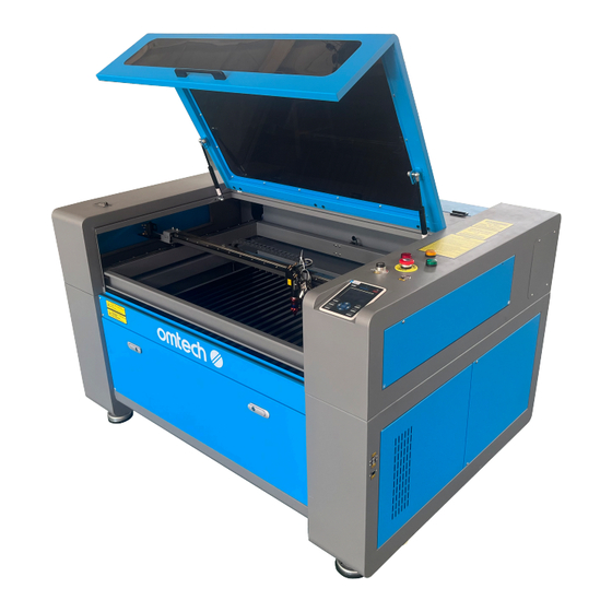
Page 8: Components
1.5 Components Y1 Y2 Y4 Y5... -
Page 9: Main Parts
Main Parts A. Cover—The cover provides access to the main bay for placing and retrieving materials, as well as fixing the laser- path alignment and other maintenance. Power to the laser is automatically cut when the cover is opened. B. Viewing Window—The polycarbonate window is shielded to protect you and others from the laser and its reflection, allowing monitoring of the engraving process. -
Page 10: Laser Head
Laser Path A. Laser Tube—This CO₂-filled glass tube is mounted on D. 3rd Mirror—This adjustable-angle mirror moves with the laser head to allow the laser beam to travel brackets and immobile. Its connection to the laser power supply is extremely high voltage and extremely dangerous. along the X axis. - Page 11 Connection Inputs A. USB Port—This port allows you to load and save designs and parameters directly onto the engraver. B. USB Line Port—This port connects to your control computer and its engraving software using any of its USB ports. C. Ethernet Port—This port connects to your control computer and its software either directly or via the internet.
-
Page 12: Control Console
Control Console Returns the machine to the saved default Stops work or returns to a previous parameters (See §4.4.16) menu Enters a command or confirms your Stops the current job selection Sets the starting point for the laser head Opens the Main menu (See §4.4.2) (See §4.4.15) Traces the outline of the current design Opens the Function menu (See §4.4.9) -
Page 13: Console Screen
Console Screen A. Graphic Display Area: Traces the processed file image during file preview display and processing. B. Parameter Display Area: Displays the file number, speed, and maximum power of the current processing file. C. Coordinate Display Area: Displays the coordinate value of the current position of the laser head. D. -
Page 14: Safety Information
2. Safety Information 2.1 Disclaimer Your engraver may differ somewhat from those shown in this manual due to options, updates, etc. Please contact us if your engraving machine came with an outdated manual or if you have any other questions. 2.2 General Safety Instructions •... -
Page 15: Laser Safety
2.3 Laser Safety Instructions When used as instructed, this machine comprises a Class 1 laser system safe for users and bystanders. However the invisible engraving laser, the laser tube, and its electrical connections remain EXTREMELY dangerous. Used or modified without care, they can cause serious property damage and personal injury including but not limited to the following: •... -
Page 16: Electrical Safety
2.4 Electrical Safety Instructions • ONLY use this device with a compatible and stable power supply with less than 5% fluctuation in its voltage. • DO NOT connect other devices to the same fuse, as the laser system will require its full amperage. Do not use with standard extension cords or power strips. - Page 17 This machine can be safely used with the following materials: Plastics • Acrylonitrile Butadiene Styrene (ABS) • Nylon (Polyamide, PA, etc.) • Polyethylene (PE) • High-Density Polyethylene (HDPE, PEHD, etc.) • Biaxially-Oriented Polyethylene Terephthalate (BoPET, Mylar, Polyester, etc.) • Polyethylene Terephthalate Glycol (PETG, PET-G, etc.) •...
-
Page 18: Installation
3. Installation 3.1 Installation Overview A complete working system consists of the laser engraving cabinet, its vent, a water tank (not included) with a pump (included), all applicable connection cables, and the laser and access keys. The cabinet can use designs provided by the enclosed engraving software by direct or internet connection with your computer;... -
Page 19: Electrical Grounding
Step 3. Check that you have received all of the following: two power cords, a ground wire, USB and Ethernet cables, a USB flash drive with engraving software included, a water pump and water piping, an exhaust pipe with a hose clamp, a ceramic resistor and its manual, a set of Allen keys, a tube of silicone sealant, an acrylic focusing tool, access keys, laser keys, repair wrenches, and this manual. -
Page 20: Water Cooling Installation
3.5 Water Cooling Installation The provided water pump is essential to your engraver's performance and longevity. When this laser works without a properly maintained cooling system, its glass tube WILL explode from excess heat. NEVER touch or adjust your engraver's water supply while the pump is connected to power. To install your pump, fill a dedicated tank with at least 7.5 litres (1.6 gal.) of distilled water. -
Page 21: Exhaust System
3.6 Exhaust System This engraver doesn’t come with an inbuilt exhaust fan. Follow the steps to set an exhaust system before use. 1. Connect the provided exhaust pipe to the port of the laser engraver, and the other end to your exhaust fan. Expand the pipe if longer is needed. -
Page 22: Initial Testing
3.9 Initial Testing Emergency Shutoff Because of the risk of fire and other hazards during engraving, this engraver includes a large and easy-to-reach emergency stop button near the control panel. Press it down to stop the laser tube instantly. When your engraver arrives, its e-stop is already pressed. Release the e-stop and press the reset button to allow the laser to function. -
Page 23: Air Assist
Water Shutoff Because of the danger posed by an uncooled laser tube, this engraver also shuts off the laser automatically when the water cooling system malfunctions. After ensuring that the emergency stop button and cover protection both work, you should also test that the water shutoff works properly before conducting any other work on your machine. -
Page 24: Operation
4. Operation 4.1 Operation Overview Operate this laser marking machine only in accordance with all the instructions provided in this manual. Failure to follow the proper guidelines detailed here can result in property damage and personal injury. This section will address only some of the options and features provided by the operation software. Before beginning to use the machine, make sure that you have read this entire manual (particularly the Safety Information above), the separate software manual, and any and all warnings provided on the machine itself. -
Page 25: Instructions For Specific Materials
Step 8. Customise your design's contrast and engraving depth by adjusting the parameters in your engraving software or directly through the control panel. If your engraving instructions detail the power setting in milliamperes, use the following conversion chart to find the appropriate power setting: Power 100% Current (mA) - Page 26 Ceramics When engraving on ceramics, generally use moderate to high power. Using more loops rather than higher power and lower speed can help avoid cracking the material during work. Be mindful of the health risk posed by dust generated from ceramic engraving, especially for repetitive industrial applications. Depending on the material and the amount of work, a fan or even full ventilation system may be required to address the problem.
- Page 27 produce poor engraving quality, noxious fumes, and even fires. High resolution engraving can cause the same problem, so medium to low resolution designs should be preferred for most plastics. Thickness of Acrylic Description 1.5 mm 3 mm 6 mm 12 mm 18 mm 24 mm Speed...
-
Page 28: Control Console
4.4 Control Console Instructions 4.4.1 Overview You can control your engraver directly from the built-in control panel, through a direct connection with your computer, or over the internet. For details on operating your engraving software, see its separate manual. The built-in control panel can operate the laser manually or engrave designs loaded onto flash drives and external hard drives connected to the USB port on the right side of the cabinet. -
Page 29: Menu Button
4.4.2 Menu Button Press Menu on the main interface to enter the Menu interface: Push ▲ or ▼ to select items, and then press Enter to enter the corresponding submenu. 4.4.3 Setting the Laser Speed Select Speed on the Menu interface, and the following dialogue box will appear: A cursor will appear when pushing ◄... -
Page 30: File Management
4.4.5 File Management Select File on the Menu interface, and the following dialogue box will appear: The system will automatically read the memory files. The file name and the work times will be listed and the selected file will be previewed in the upper right corner. Different memory files can be selected by using ▲ or ▼. Press Enter to preview the selected file on the main interface. -
Page 31: Reading Usb Files
4.4.6 Reading USB Files If Udisk+ is pressed, the display will show: • Read Udisk: Reads the file list in the inserted USB drive. • Copy to Memory: Copies the target file to the system. • Delete: Deletes the selected file from the USB drive. The system supports FAT16 and FAT32 formats, but files can only be identified when placed in the root directory of the flash drive. -
Page 32: Engraving Layer Adjustment
4.4.8 Adjusting Engraving Layers When the system is idle or the work is finished, press Enter to enter the layer parameter section. Push ▲ or ▼ to select the intended layer. Press Enter to check the selected layer's parameters as shown below: Layer0 Layer0 Speed... -
Page 33: Z Axis
4.4.11 Adjusting the U Axis When U Move is selected, push ◄ or ► to control the movement of the U axis. This can be used to control the rotational position of a rotary axis or the linear position of an automatic feed (both sold separately) if either is installed. -
Page 34: Setting The Origin
4.4.15 Setting the Origin When Origin Set+ is selected, press Enter and the display will show: Press Fn to select an item. When Multi Origin Enable is selected, press Enter to enable or disable the item. When enabled, the small box will be red and, when disabled, the small box will be grey. When selecting Set Origin or Next Origin, push ◄... -
Page 35: Default Parameter Adjustment
4.4.16 Adjusting Default Parameters When Set Fact. Para. is selected, the following interface will be displayed: Push ◄ or ► and ▲ or ▼ to select a password and press Enter to save it. The current parameters of the machine will be stored as its defaults. -
Page 36: Ip Address
4.4.20 Setting the Machine's IP Address When IP Setup+ is selected, press Enter and the display will show: Press Fn to select an item, and push ◄ or ► and ▲ or ▼ to change the parameters. The default address of the engraver is 192.168.1.100. -
Page 37: Screen Interface
4.4.22 Setting the Screen Reference When Screen Origin is selected, press Enter and the display will show: This interface sets the relative position of the origin. Different origin positions can generate different reflections of the graph over the X/Y axis. The operation method is the same as those described above. 4.4.23 Alarm Display During the operation of the system or the running of the machine, some alarm information may pop up if there is a water protection error etc. -
Page 38: Maintenance
5. Maintenance 5.1 Maintenance Overview The use of procedures other than those specified herein may result in hazardous laser radiation exposure. Before any cleaning or maintenance work, always switch off the device and disconnect it from its power supply. Always keep the system clean, as flammable debris in the working and exhaust areas constitutes a fire hazard. ONLY allow trained and skilled professionals to modify or disassemble this device. -
Page 39: Main Bay & Engraver
If the water remains visibly clean at all times, it is still recommended that you clean the water tank about once a month as a precaution, changing the water as you do so. If you use an industrial water chiller instead of the provided pump, follow its separate instructions for maintenance but similarly ensure that the water used remains cool, clean, and pure. - Page 40 Remove the pressurised air hose and laser guide connections. Once positioned over your clean lens-cleaning tissue, remove the lens from the lens holder by carefully turning the lens holder and letting the lens and its O-ring drop onto the cleaning cloth. Examine the O-ring and, if necessary, clean it with a cotton bud and a lens-cleaning tissue or cloth.
-
Page 41: Mirrors
5.3.4 Cleaning the Mirrors The mirrors should be similarly cleaned if there is any debris or haze on their surface to improve performance and avoid permanent damage. The 1st mirror is located in the back left of the machine beyond the far end of the Y axis. The end of the laser tube closest to this mirror is itself a semitransparent mirror that should be checked at the same time. -
Page 42: Laser Tube
5.4.1 Laser Tube Alignment To test the alignment of the laser tube with the 1st mirror, cut out a piece of tape and place it on the mirror's frame. DO NOT place the tape directly onto the mirror. Turn on the machine and set the power level to 15% or lower. Press Pulse to manually fire the laser. -
Page 43: First Mirror
5.4.2 1st Mirror Alignment After ensuring the laser is well aligned between the laser tube and 1st mirror, check the alignment between the 1st and 2nd mirrors. First, use the direction arrows on the control panel to send the 2nd mirror to the back of the bed along the Y axis. -
Page 44: Second Mirror
5.4.3 2nd Mirror Alignment After ensuring the laser is well aligned between the 1st and 2nd mirrors, check the alignment between the 2nd and 3rd mirrors. Repeat the steps and adjustments above, taking care to use the tape on the mirror's frame and not its surface. 5.4.4 3rd Mirror Alignment After ensuring the laser is well aligned between the 2nd and 3rd mirrors, check the alignment between the 3rd mirror and the workbed. -
Page 45: Parts Replacement
QR code to the right. Come join the OMTech community at our official laser group on Facebook or visit the company forums at omtechlaser.com! Check our YouTube channel for helpful hints and instructional videos. - Page 46 U S B - 0 9 0 6 - X 2 Rev. 25 Jun. 2024...
Need help?
Do you have a question about the USB690f and is the answer not in the manual?
Questions and answers