Advertisement
Available languages
Available languages
Quick Links
Operating instructions
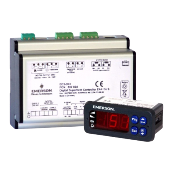
EC3-D73 Digital Superheat Controller (24V/230V)
General information:
EC3-D73 is the superheat controller for stepper motor driven Electrical Control Valves
EX4-6 from COPELAND and is optimized to operate with the Copeland Digital Scroll series
utilizing a 0-10V input from a third-party controller. The controller synchronizes the PWM
digital compressor solenoid valve with the superheat controlled by the electrical control
valve; EX series. It can only be set-up via the ECD-002 display.
.
WARNING: The controller has a potential ignition source and has not been qualified
according to ATEX standards. Installation only in "non-explosive location".
Safety instructions:
• Read operating instructions thoroughly. Failure to comply can result in device failure,
system damage or personal injury.
• This product is intended for use by qualified personnel having the appropriate
knowledge and skills like trained according to EN 13313 or a specific training for
flammable refrigerants.
• Flammable refrigerants require special handling and care due to its flammability.
Sufficient ventilation is required during service of the system. Contact with rapidly
expanding gases can cause frostbite and eye damage. Proper protective equipment
(gloves, eye protection, etc.) has to be used.
• Ensure that the system is correctly labelled with applied refrigerant type and a warning
for explosion risk.
• In a severely contaminated system, avoid breathing acid vapours and avoid contact
with skin from contaminated refrigerant / lubricants. Failure to do so could result in
injury.
• Before opening any system make sure pressure in system is brought to and remains at
atmospheric pressure.
• Do not release any refrigerant into the atmosphere!
• Do not exceed the specified maximum ratings for temperature, voltage and current.
• Ensure that the system piping is grounded.
• Before installation or service disconnect all voltages from system and device.
• Ensure that design, installation and operation comply with European and national
standards/regulations.
• Do not operate system before all cable connections are completed.
• Disposal: Electrical and electronic waste must NOT be disposed of with other
commercial waste. Instead, it is the user responsibility to pass it to a designated
collection point for the safe recycling of Waste Electrical and Electronic Equipment
(WEEE directive 2012/19/EU). For further information, contact your local environmental
recycling center.
• For flammable refrigerants only use valves and accessories approved for it!
• Electronic devices are subject to electromagnetic interference. Ensure that all
components in the system are sufficiently protected.
Note: The EC3-D73 series contains
acid battery.
The battery must NOT be disposed of with other commercial waste. Instead,
it is the user's responsibility to pass it to a designated collection point for the safe recycling
of batteries (harmonized directive 2012/19/EU). For further information contact your local
environmental recycling center.
Mounting position:
The EC3-D73 is designed to be mounted onto a standard DIN rail. Mounting position: on
vertical walls, with stepper motor connector on top side only.
Mounting of ECD-002:
•
ECD-002 can be installed at any time also during operation.
•
ECD-002 can be mounted in panels with 71x29 mm
cutout.
•
Push controller into panel cut-out.(1)
•
Make sure that mounting lugs are flush with outside
of controller housing
•
Insert Allen key into front panel holes and turn
clockwise. Mounting lugs will turn and gradually
move towards panel (2)
•
Turn Allen key until mounting lug barely touches
panel. Then move other mounting lug to the same
position (3)
•
Tighten both sides very carefully until keypad is
secured. Do not over tighten as mounting lugs will
break easily.
!
Electrical Installation:
•
Refer to the electrical wiring diagram for electrical connections.
•
Do not apply voltage to the controller before completion of wiring.
•
Ground the metal housing with a 6.3 mm spade connector.
•
Keep controller and sensor wiring well separated from mains wiring. Minimum
recommended distance 30 mm.
•
Use a class II category transformer for 24 VAC power supply. Do not ground the 24 VAC
lines. We recommend using individual transformers for EC3 controller(s) and for 3
controllers to avoid possible interference or grounding problems in the power supply.
Connecting any EC3 inputs to mains voltage will permanently damage the EC3.
•
The use of the relay is essential to protect the system in case of power failure if the
communications interface or the ECD-002 are not utilized.
•
If the output relay is not utilized, the user must ensure appropriate safety precautions are
in place to protect the system against damage caused by a power failure.
•
In order to provide system protection in the event of power loss, it is recommended to
change the battery annually.
Copeland Europe GmbH
Pascalstrasse 65 I 52076 Aachen I Germany
a VRLA battery = valve regulated rechargeable lead-
D73_A1_A2L_EN_DE_R09_865019.docx
Digital input status is dependent to operation of compressor/0-10V input
System
Operating
condition
C1 &
C2 in stop mode
C1 in run &
C2 in stop mode
C1 &
C2 in run mode
C1 in stop &
C2
starts
run
mode
Note 1: C1 = Compressor 1, C2 = Compressor 2
Note 2: Digital comp. should always be regarded as base load compressor 1.
Wiring:
A:
White wire
B:
Black wire
C:
Blue wire
D:
Brown wire
E:
M12 Plug cable assembly EXV-Mxx for connection to EX4-6
F:
24 V /230V Triac output to PWM Digital Scroll valve
G:
Remote control panel, system controller.
H:
Alarm relay, dry contact. Relay coil is not energized at alarm or power off.
I:
Digital input "Cooling demand" (0 V/open = Stop; 24 V/closed = Start)
J:
Transformer Class II, 24 VAC secondary / 25 VA
K:
Third party controller (can use the analog output signal from EC3)
L:
Pump down relay, dry contact. Relay is energized during normal operation
M:
Digital input 2: "Comp 2 running"
(0 V/ open = Comp 2 stop; 24 V /closed = Comp. 2 running)
N:
Discharge Temp. Sensor Copeland® NTC
O:
0-10 V Digital Scroll capacity demand signal from system controller
rd
party
P:
TP1-NP... Temperature sensor
Date: 19.06.2024
OI_EC3-
0-10V input from third party
Digital Inputs
controller
"Cooling demand" open (0 V)
EXV remains closed irrespective
"Comp 2 Running" open (0 V)
of voltage input value
EXV active
"Cooling demand" closed (24 V)
Input = 0V: dig. valve capacity =
"Comp 2 Running" open (0 V)
10% default capacity.
If dig. comp. is in by-pass,
EXV will:
"Cooling demand" closed (24 V)
EXV active
"Comp 2 Running" closed (24 V)
EXV always modulates even
when the dig. compr. is in by-
pass mode.
"Cooling demand" open (0 V)
EXV remains closed irrespective
"Comp 2 Running" closed (24 V)
of voltage input value
P/N 865019/Rev.09
EN
- close if capacity is <70%
- be inhibited if capacity is
>70%
Advertisement

Related Manuals for Copeland EC3-D73


Summary of Contents for Copeland EC3-D73
- Page 1 (harmonized directive 2012/19/EU). For further information contact your local environmental recycling center. Mounting position: The EC3-D73 is designed to be mounted onto a standard DIN rail. Mounting position: on vertical walls, with stepper motor connector on top side only. Mounting of ECD-002: •...
- Page 2 (must be checked and modified if necessary) Vacuum the entire refrigeration system. Factory Field • Note: COPELAND Electrical Control Valves EX4-6 are delivered at half open position. Code Parameter description and choices setting setting Do not charge system before closure of valve.
- Page 3 Alarm relay Valve recovery/replacement Regulating After selecting the parameters the EC3-D73 is fully functional without connected PC or Regulating keypad/display unit ECD-002. Signaling Fully close Auto Ab (blinking) Signaling...
- Page 4 EXV control loop remains active when input is 24 V and the digital scroll is idle. NTC input; Coil-out temperature sensor COPELAND temperature sensor TP1-NP… NTC input; Discharge temperature sensor Copeland® NTC 86 kΩ at +25 °C 4-20 mA Analog input COPELAND PT5... Pressure Transmitter 4-20 mA Analog output...
- Page 5 Regelventile EX4-6 in Anlagen mit Copeland Digital Scroll. Der Leistungsbedarf der Anlage Kommunikations-Schnittstelle oder ECD-002 nicht verwendet werden! wird über den 0...10 V Eingang von einem externen Regler eingespeist. Der EC3-D73 • Wird das Alarmrelais nicht verwendet, muss das System auf andere Weise vor Schäden synchronisiert das Magnetventil des Digital Scroll mit dem elektrischen Expansionsventil.
- Page 6 Vorbereitungen für Inbetriebnahme: • Parametertabelle: • Den gesamten Kältekreislauf vakuumieren. (im Regler hinterlegte Reihenfolge) • Hinweis: Elektrische Regelventile von COPELAND EX4-6 werden halbgeöffnet Code Beschreibung und Wahlmöglichkeiten Werk Kunde ausgeliefert. Den Kältekreislauf nur bei geschlossenem Ventil mit Kältemittel füllen. •...
- Page 7 Code Beschreibung und Wahlmöglichkeiten Werk Kunde EC3-D73 hat eine potenzielle Zündquelle und entspricht nicht den ATEX Ausgabe Logik Bestimmungen. Installation nur in nicht explosionsgefährdeter Umgebung. Für 0: Alarm = normal, Abpumpen = normal brennbare Kältemittel nur Ventile und Zubehörteile, die dafür zugelassen sind,...
- Page 8 Bei 24 V bleibt das EX Ventil aktiv, auch wenn der Digital Scroll im Leerlauf arbeitet. NTC Analogeingang COPELAND Temperatursensor TP1-NP… NTC Analogeingang für Copeland® NTC 86 kΩ bei 25 °C Sensor Austrittstemperatur 4-20 mA Analogeingang COPELAND PT5... Drucktransmitter 4-20 mA Analogausgang für externen Regler mit 12/24 VDC Speisespannung und geeignetem internen Widerstand...
Need help?
Do you have a question about the EC3-D73 and is the answer not in the manual?
Questions and answers