Copeland E2 Quick Start Manual
Hide thumbs
Also See for E2:
- Operator's manual (26 pages) ,
- User manual (18 pages) ,
- Quick start manual (15 pages)
Advertisement
Quick Links
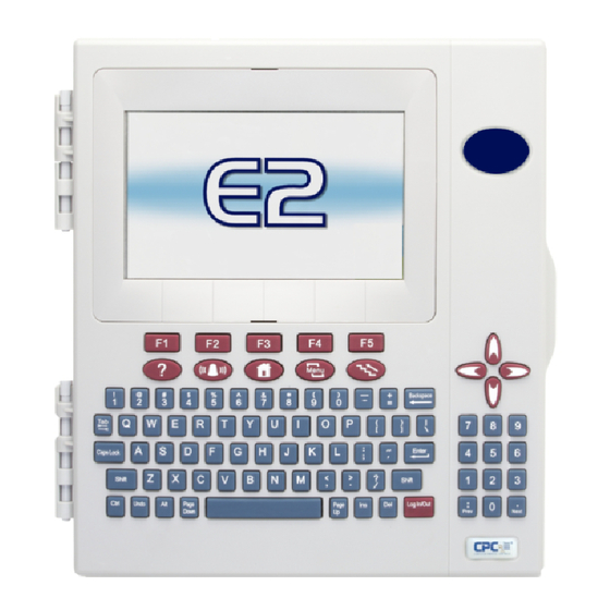
E2 Controller
For a copy of the full E2 User Manual (P/N 026-1614), visit
en-us/products/controls-monitoring-systems/facility-controls-electronics/facility-and-
system-controls/e2-facility-management-system
Customer Service at 770-425-2724.
Installing the E2 Controller
Mount the E2 Controller in a location suitable for Type 1
(NEMA1) equipment.
1.
Connect the I/O or MODBUS Network to one or all of
the E2 RS485 I/O or MODBUS Network ports. (A
maximum of 31 devices can be wired to each I/O or
MODBUS Network port.)
2.
If the E2 is the beginning of all RS-485 I/O or MODBUS
Networks, set all three jumpers to the UP position. For
MODBUS, set the jumpers in the top-most position
(MOD). For I/O Net, set the jumpers in the middle
position (I/O). For no termination, set the jumpers to the
DOWN position (NO).
3.
Connect earth ground to one of the two ground
terminals provided. Use 12 AWG (preferred) or 14 AWG
wire and keep as short as possible (less than 12 inches
preferred).
4.
Connect 24VAC Class 2 to the power terminals.
5.
Flip the power switch to the ON position. When 24VAC
has been applied to the board, the green LED will
illuminate.
026-4143 R5
©2024 Copeland LP.
https://www.copeland.com/
to download or contact Copeland
QUICK START GUIDE
Advertisement

Related Manuals for Copeland E2


Summary of Contents for Copeland E2
- Page 1 QUICK START GUIDE E2 Controller For a copy of the full E2 User Manual (P/N 026-1614), visit https://www.copeland.com/ en-us/products/controls-monitoring-systems/facility-controls-electronics/facility-and- system-controls/e2-facility-management-system to download or contact Copeland Customer Service at 770-425-2724. Installing the E2 Controller Mount the E2 Controller in a location suitable for Type 1 (NEMA1) equipment.
- Page 2 Press the keys to open the General Help menu. Logging Into the E2 Controller From the Main Menu: When the E2 is powered up for the first time, the user is Press (System Configuration).
- Page 3 Responsibility for proper selection, use and maintenance of any product remains solely with the purchaser and end-user. ©2024 Copeland is a trademark of Copeland LP.
Need help?
Do you have a question about the E2 and is the answer not in the manual?
Questions and answers