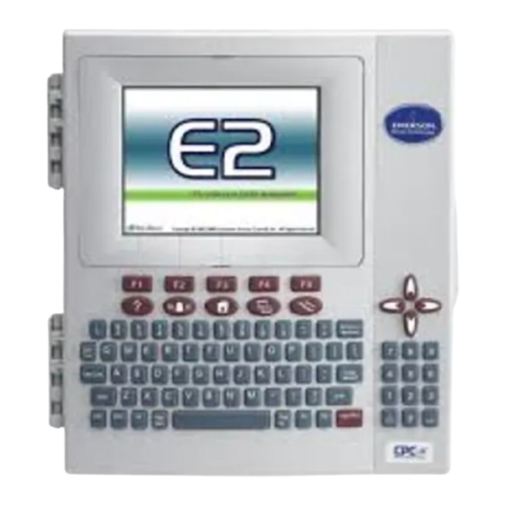
Copeland E2 Enhanced Technical Bulletin
Rx and bx controllers and rmcc/bec/bcu retrofitting
Hide thumbs
Also See for E2 Enhanced:
- Operator's manual (26 pages) ,
- User manual (18 pages) ,
- Quick start manual (15 pages)
Advertisement
Quick Links
E2 Enhanced RX and BX Controllers
and RMCC/BEC/BCU Retrofitting
Overview
This technical bulletin describes E2E retrofitting of supermarkets with existing REFLECS controllers.
STEP 1: Preparing for Retrofit
When replacing a REFLECS unit with an E2E, there are several major differences that must be taken into account.
1.
All REFLECS units are powered by 110/220VAC line voltage. E2E controllers are powered by 24VAC non center-
tapped transformers. Refer to the E2 User's Manual (P/N 026-1614) for more information on powering the E2E
controller.
2.
REFLECS units use an RS485 (COM B) network to connect to a 485 Alarm Panel. E2E does not support the 485
Alarm Panel.
3.
REFLECS units use an RS232 (COM C) host network to connect all units to a modem for alarm dial-out. E2Es may
use either Echelon or Ethernet for box-to-box communication. The existing host network wiring may not be used
for E2E box-to-box communication - you will either have to rewire using approved Echelon network wire, or wire
CAT 5 cable to an approved network router or switch. Refer to the E2 User's Guide for more information on box-to-
box wiring.
4.
COM A and COM D networks (the RS485 I/O networks) use the same wire and polarity for both the REFLECS and
E2E controllers. No rewiring of the I/O network will be necessary; just unplug the COM A and/or COM D connectors,
and plug them into the I/O port(s) on the E2E PIB (see "Transferring the COM A and COM D Networks" below).
STEP 2: Transferring the COM A and COM D Networks
The COM A and COM D I/O networks on the RMCC/BEC/BCU are where connections to all I/O devices, such as 16AIs and
8ROs are made. The two networks are interchangeable, each one capable of connecting up to 31 devices.
The E2E's standard I/O port (COM2, located on the E2E Power Interface Board, or PIB) also has two connectors
(Figure 1). Unplug the connectors from the COM A and COM D plugs, and plug them into the COM2 plugs on the E2E.
STEP 3: E2E Termination Jumper Settings
The network termination jumpers, directly above the two COM2 plugs on the PIB, will need to be set to the same positions
as the COM A and COM D termination jumpers on the RMCC/BEC/BCU. The rules for termination on E2E I/O networks are
the same as the rules for RMCC/BEC/BCU I/O networks. Set the three jumpers to the middle I/O (terminated) position if the
port is at the end of a network segment or the hub of a star configuration, and down NO (unterminated) if the port is in the
middle of a segment.
026-4157 R1
©2024 Copeland LP.
TECHNICAL BULLETIN
Advertisement

Summary of Contents for Copeland E2 Enhanced
- Page 1 TECHNICAL BULLETIN E2 Enhanced RX and BX Controllers and RMCC/BEC/BCU Retrofitting Overview This technical bulletin describes E2E retrofitting of supermarkets with existing REFLECS controllers. STEP 1: Preparing for Retrofit When replacing a REFLECS unit with an E2E, there are several major differences that must be taken into account.
- Page 2 E2 Enclosure (Right Side) COM1 Serial Device RS232 Port Plug-In COM3 Modem Card POWER INTERFACE BOARD (PIB) Termination Serial Device Jumpers RS485 COM Ports Termination Jumpers COM2 COM6 COM4 Figure 1- COM2 Port Location, E2E (Right Side Interior) 026-4157 R1 ©2024 Copeland LP.
- Page 3 Responsibility for proper selection, use and maintenance of any product remains solely with the purchaser and end-user. ©2024 Copeland is a trademark of Copeland LP.


Need help?
Do you have a question about the E2 Enhanced and is the answer not in the manual?
Questions and answers