Table of Contents
Advertisement
Quick Links
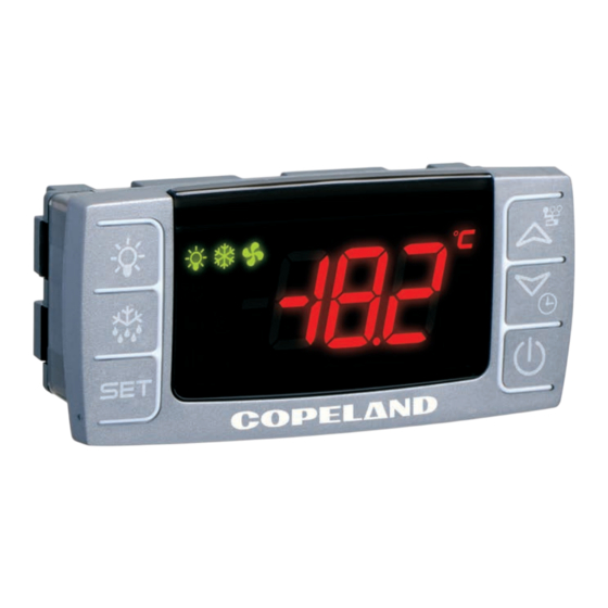
XM679K 5.4
Controllers for Multiplexed Cabinets
1
Introduction
1.1
General Warning
Please read the following safety precautions and warnings before using this manual:
• This manual is part of the product and should be kept near the device for easy and quick reference.
• The device should not be used for purposes different from those described in this manual.
It cannot be used as a safety device.
CAUTION
• Check the application limits before proceeding.
• Copeland reserves the right to change the composition of its products, even without notice,
ensuring the same and unchanged functionality.
SAFETY PRECAUTIONS!
• Check that the supply voltage is correct before connecting the device.
• Do not expose to water or moisture: use the controller only within the operating limits and avoid
sudden temperature changes with high atmospheric humidity to prevent condensation from
forming.
• Warning: Disconnect all electrical connections before performing any kind of maintenance.
• Fit the probe where it is not accessible by the end user. The device must not be opened.
CAUTION
• In case of failure or faulty operation, send the device back to the distributor or to Copeland with a
detailed description of the fault.
• Verify the maximum current that can be applied to each relay (see Section 19, Technical Data).
• Ensure that the wires for probes, loads, and the power supply are separated and far enough from
each other without crossing or intertwining.
• In case of applications in industrial environments, the use of main filters in parallel with inductive
loads could be useful.
026-4279 R3
©2024 Copeland LP.
QUICK START GUIDE
Advertisement
Table of Contents

Subscribe to Our Youtube Channel
Related Manuals for Copeland XM679K


Summary of Contents for Copeland XM679K
- Page 1 • Fit the probe where it is not accessible by the end user. The device must not be opened. CAUTION • In case of failure or faulty operation, send the device back to the distributor or to Copeland with a detailed description of the fault.
-
Page 2: Before Proceeding
The XM679K is a high level microprocessor based controllers for multiplexed cabinets suitable for applications on medium or low temperature. The XM679K can be inserted in a LAN of up to eight (8) different sections which can operate, depending on the programming, as a stand alone controller or following the commands coming from the other sections. -
Page 3: Installation And Mounting
Avoid places subject to strong vibrations, corrosive gases, excessive dirt or humidity. The same recommendations apply to probes. Allow air to circulate through the cooling holes. Figure 4-1 - CX660 Keyboard Installation and Mounting Dimensions Figure 4-2 - CX660 and CH660 Dimensions 026-4279 R3 ©2024 Copeland LP. -
Page 4: Wiring Diagram And Connections
NOTE: The jumper indicated as JMP is inside the case of the controller PLEASE DISCONNECT THE POWER SUPPLY BEFORE MOVING IT. This jumper must be closed only in case of driving 24Vac valve. XM679K- 230VAC Valves Figure 5-1 - Wiring and Connections Models with 115V supply: use terminals 8-7 for supply. -
Page 5: Keyboard Display Cx660
Figure 5-4 - LAN Connection If the LAN is connected properly, the green LED will be ON. If the LAN is not connected properly, a blinking NOTE LED will display. The maximum allowed distance is 30 meters. 026-4279 R3 ©2024 Copeland LP. -
Page 6: How To Use A Single Pressure Transducer On Multiplexed Applications
Figure 5-6 - Pressure Transducer on Multiplexed Applications A working LAN connection is required (green LED illuminated on all XM670- XM679K boards of the same LAN). Connect and configure the pressure transducer only on one XM670- XM679K of the network. Afterwards, the pressure value read by that single transducer will be used by each device connected to the same LAN. -
Page 7: How To Connect The Monitoring System
The analog output is located near the terminal [39] on a two-pin connector. The analog output can be used to control anti-sweat heaters using a chopped phased controller, XRPW500 (500 watt) or family, XV...D or XV...K. 026-4279 R3 ©2024 Copeland LP. - Page 8 Quick Reference Guide in Running the Self Adaptive Regulation After wiring the XM679K; set the proper gas via Fty parameter. Set the proper gas via Fty parameter. Preset gas is R404A. Table 6-1 - XM679K Gas Table LABEL REFRIGERANT OPERATING RANGE -58 to 120°F / -50 to 60°C...
- Page 9 • If the capacity of the valve is higher than requested, it can be reduced by the parameter. MNF (default is 100). A proper setting of MnF will reduce the time that the algorithm takes to reach the stability. MNF value does not affect the bandwidth. 026-4279 R3 ©2024 Copeland LP.
-
Page 10: User Interface
User Interface Figure 7-1 - XM679K Display Icons Table 7-1- XM679K Display Icons Cooling Output Light The output is activated when the icon is ON. A delay is present when the icon is blinking. Defrost Auxiliary relay MEASUREMENT UNIT Energy Saving Multimaster enabled °C, Bar, and... -
Page 11: Double Commands
In any case, it is possible to wait for about 10 seconds to exit. In order to show the air temperature set is sufficient to press and release the SET button, the value is displayed for about 60 seconds for a KEY COMBINATIONS. 026-4279 R3 ©2024 Copeland LP. -
Page 12: How To Program The Parameters (Pr1 And Pr2)
Enter the Pr2 level and select the desired parameter then press the SET+ down arrow keys. If the LED on the left-hand side of the screen is ON, it means that the parameter is present in Pr1 level; if the LED is OFF, it means that the parameter is not present in Pr1 (Only Pr2). 026-4279 R3 ©2024 Copeland LP. -
Page 13: Fast Access Menu
Number of devices in the LAN LAn Address list of devices in the LAN GAL To see all the active alarms in each device connected to the LAN EXIT Press together or wait the time out for 60 seconds. 026-4279 R3 ©2024 Copeland LP. -
Page 14: Multi-Master Function Menu (Sec)
ALL. Exit from the multi-master menu. Enter the programming menu and change the required parameter values. The new values will be changed on all devices connected to the LAN. CAUTION At the end of programming, select the LOC section to switch OFF the icon. 026-4279 R3 ©2024 Copeland LP. -
Page 15: Synchronized Defrost
12°C safety settings (read only). See Figure 10-2 for an example of configuration: 06:00 1° 06:00 1° 06:00 1° 14:00 2° 14:00 2° 14:00 2° 22:00 3° 22:00 3° 22:00 3° Figure 10-2 - Configuration Example 026-4279 R3 ©2024 Copeland LP. -
Page 16: Clock Setting And Rtc Alarm Reset
[4] From the EEV submenu: Select the correct kind of gas with the FTy parameter. [5] Use the following parameters to set up the correct valve drive (based on the valve data sheet of the manufacturer). 026-4279 R3 ©2024 Copeland LP. -
Page 17: Regulation For Superheat: Self Adaptive Or Manual Operating Mode
Regulation pauses can be realized using Sti and Std parameters (during these pauses the valve is closed). Increasing the Int integral time can decrease the speed of reaction of the regulator on the HY band. 026-4279 R3 ©2024 Copeland LP. -
Page 18: Valve Capacity Reducing - Mnf Parameter
This can be done by the parameter AnP. Suggested values: • From 1-5 evaporators for each racks: AnP = 5-6 • From 6-30 evaporators for each racks: AnP = 3-4 • More than 30 evaporators for each racks: AnP = 2-3 026-4279 R3 ©2024 Copeland LP. -
Page 19: Display Messages
Alarm reset Alarm output deactivated. noP, nP Not present (configuration) Not available (evaluation) The keyboard is not able to communicate with Verify the connection or call Copeland Technical the XM669K or XM679K Services. ALARM FROM PROBE INPUT Sensor brake down, value out of range or P1: the cooling output works with Con and COF sensor incorrectly configured P1C, P2C to P6C. -
Page 20: Alarm Recovery
Temperature alarms HA, LA, HA2, and LA2 automatically stop as soon as the temperature returns to normal values. Alarms EA and CA (with i1F = bAL) recover as soon as the digital input is disabled. Alarm CA (with i1F = PAL) recovers only by switching the device OFF and ON. 026-4279 R3 ©2024 Copeland LP. -
Page 21: Controlling Loads
14 Electronic Expansion Valve Menu (For XM679K Only) Enter the Programming mode by pressing the SET and DOWN key for few seconds (measurement unit starts blinking). Press arrow until instrument shows EEU label. Press SET, then you will be in the EEV function menu. -
Page 22: Standard Regulation And Continuous Regulation
Figure 15-3 - First Kind Regulation Diagram of superheat precision. This second method can be used only in centralized plants and is available only with electronic expansion valve by selecting the CrE=Y parameter. 026-4279 R3 ©2024 Copeland LP. - Page 23 15.4.2 Second Kind of Regulation – 15.6 Defrost Continuous Regulation (Only XM679K) 15.6.1 Defrost Starting In this case, the Hy parameter is the proportional band of PI in charge of room temperature regulation and it is In any case, the device checks the temperature that is read by recommended to use at least Hy=5.0°C/10°F.
- Page 24 NOTE: With CrE=”y” or CrE=”EUP” or CrE=EU5 only «RTC defrost» and «interval defrost» are allowed. With EdF=”Aut” & CrE=”y” or CrE=”EUP” or CrE=EU5 the «interval defrost» will be performed, as with EdF = in Figure 15-5 - Control With Analog Output 026-4279 R3 ©2024 Copeland LP.
-
Page 25: Anti-Sweat Heaters
LAN or probe not connected P4C = NTC, PtC or PtM LAN or probe not connected trA = AC if the device has the analog output OA6 = AC if the device will use the AUX relay for regulation 026-4279 R3 ©2024 Copeland LP. -
Page 26: Auxiliary Output
During the Cleaning Status, the display shows the “cLn” message. 15.11 Auxiliary Output The auxiliary output is switched ON and OFF by means of the corresponding digital input, or by pressing and releasing the down arrow key. 026-4279 R3 ©2024 Copeland LP. -
Page 27: Parameter List
IN is Setpoint Plus Differential (Hy). Solenoid valve Cut OUT is when the temperature reaches the setpoint. Integral time for room temperature regulation (Only XM679K): (0 to 255 seconds) Integral time for room temperature PI regulator. 0 = no integral action. - Page 28 WARNING: The setting of PrU is used for all the pressure parameters. If PrU=rEL all pressure parameters are in relative pressure unit, if PrU=AbS all pressure parameters are in absolute pressure unit. (Only XM679K) Pressure measurement unit: (bAr – PSI - MPA) It selects the pressure measurement units.
- Page 29 Table 16-1 - Parameter List Parameter Description ELECTRONIC EXPANSION VALVE SUBMENU (Only XM679K) Kind of gas: LABEL REFRIGERANT OPERATING RANGE -58 to 120°F / -50 to 60°C r134A -58 to 120°F / -50 to 60°C r290 – Propane -58 to 120°F / -50 to 60°C r404A -94 to 120°F / -70 to 60°C...
- Page 30 Minimum Operating Pressure threshold: (PA4 to P20 bar / psi / kPA*10) If the suction pressure comes down to this value a low pressure alarm is signaled with LOP alarm. (related to PrM parameter). 026-4279 R3 ©2024 Copeland LP.
- Page 31 AUt = on demand defrost. Heater setpoint during defrost: (-55.0 to 150.0°C; -67 to 302°F) If tdF = EL during the defrost the defrost relay perform an ON/OFF regulation with Srt as setpoint. 026-4279 R3 ©2024 Copeland LP.
- Page 32 First defrost after start-up: Y = Immediately; N = after the IdF time Defrost delay after continuous cycle: (0 to 23.5 hours) Time interval between the end of the fast freezing cycle and the following defrost related to it. 026-4279 R3 ©2024 Copeland LP.
- Page 33 Fan OFF time: (0 to 15 minutes) with Fnc = C_n or C_y, (fan activated in parallel with compressor). it sets the evaporator fan off cycling time when the compressor is off. With Fon =0 and FoF ≠ 0 the fan are always off, with Fon=0 and FoF =0 the fan are always off. 026-4279 R3 ©2024 Copeland LP.
- Page 34 Differential for second temperature alarm: (0.1°C to 25.5°C / 1°F to 45°F) Intervention differential for recovery of second temperature alarm. Second temperature alarm delay: (0 to 255 minutes) Time interval between the detection of second temperature alarm condition and the corresponding alarm signaling. 026-4279 R3 ©2024 Copeland LP.
- Page 35 Sti time, the valve closes for Std time in order to prevent ice creation. Stop duration (Only XM679K): (0 to 60 minutes) It defines stop regulation time after Sti. Disabling alarm relay by pressing a key: (N; Y) OPTIONAL OUTPUT (only for XM679K) Relay at term.
- Page 36 HES so that the operation setpoint is SET + HES. Energy Saving cycle length during workdays: (0 to 24 hours 00 minutes) Sets the duration of the Energy Saving cycle on workdays. Energy Saving cycle start on holidays. (0 to 23 hours 50 minutes) 026-4279 R3 ©2024 Copeland LP.
- Page 37 LdS = y); N= the displayed value is the local probe one. Remote pressure probe: N= the value of pressure probe is read from local probe; Y= the value of pressure probe is sent via LAN. P4 probe sent via LAN (N,Y) 026-4279 R3 ©2024 Copeland LP.
- Page 38 Probe 5 configuration: (nP – Ptc – ntc – PtM – 420 – 5Vr) nP= not present; PtM= Pt1000; 420= 4 to 20mA; 5Vr= 0 to 5V ratiometric; (Only XM679K) Probe 5 calibration: (-12.0 to 12.0°C/ -21 to 21°F) allows to adjust possible offset of the probe 5.
- Page 39 Release software: (read only) Software version of the microprocessor. Software sub-release: (read only) For internal use. Parameter table: (read only) It shows the original code of the Copeland parameter map. Access to the protected parameter list (read only). 026-4279 R3...
- Page 40 OP: the 17.6 Relay Aux Actuation (AUS) digital input is activated by opening the contact. This function allows to turn ON and OFF the auxiliary relay by using the digital input as external switch. 026-4279 R3 ©2024 Copeland LP.
-
Page 41: Use Of The Programming Hot Key
• Err = Failed programming. In this case, press the SET key if you want to restart the programming again or remove the unprogrammed Hot-Key. Remove the Hot Key. NOTE: The upload procedure will overwrite everything previously uploaded from the last Hot Key upload. 026-4279 R3 ©2024 Copeland LP. -
Page 42: Technical Data
19 Technical Data Table 19-1- XM679K Technical Specifications CX660 KEYBOARD Housing Self-extinguishing ABS Case: CX660 fascia Front: 35 mm x 77 mm Depth: 18 mm Dimensions Panel Mount: 29 mm x 71 mm panel cut-out IP20 Protection Frontal: IP65 Power Supply... -
Page 43: Default Setting Values
Pressure displaying mode: temperature or pressure Resolution (only C): decimal, integer Local display: default display Remote display: default display Display delay Regulation probe A Regulation probe B Regulation probe 3 Regulation probe 4 Regulation probe 5 026-4279 R3 ©2024 Copeland LP. - Page 44 Delay for high pressure alarm activation (MOP) -0.5 -0.5 -0.5 -0.5 Minimum value threshold of suction pressure Delay for low pressure alarm activation (LOP) Opening steps variation during MOP and LOP Low superheat alarm with "XeCO2 function active 026-4279 R3 ©2024 Copeland LP.
- Page 45 Storage in EEPROM defrost interval Minimum Defrost Time Maximum defrost duration Delay for defrost on call Visualization during defrost Visualization delay for temperature after defrost Dripping time Defrost at power ON Delay defrost after freezing 026-4279 R3 ©2024 Copeland LP.
- Page 46 2:The control period for the anti-sweat control Probe for temperature alarm Temperature alarm configuration: relative / absolute High temperature alarm setting Low temperature alarm setting Differential for temperature alarm Temperature alarm delay Probe for temperature alarm 2 026-4279 R3 ©2024 Copeland LP.
- Page 47 Digital input 3 configuration Digital input 3 activation delay Pressure switch number Compressor and fan status when open door Outputs restart after door open alarm Clock presence Current hour Current minutes Current day First weekly day 026-4279 R3 ©2024 Copeland LP.
- Page 48 Defrost Synchronization Defrost end Synchronization Setpoint Synchronization Display Synchronization (temperature sent via LAN) ON/OFF Synchronization Light Synchronization AUX Synchronization Energy Saving Synchronization Remote probe displaying Pressure value sent in LAN P4 probe sent via LAN 026-4279 R3 ©2024 Copeland LP.
- Page 49 The contents of this publication are presented for informational purposes only and they are not to be construed as warranties or guarantees, express or implied, regarding the products or services described herein or their use or applicability. Copeland reserves the right to modify the designs or specifications of such products at any time without notice.
Need help?
Do you have a question about the XM679K and is the answer not in the manual?
Questions and answers