Table of Contents

Subscribe to Our Youtube Channel
Related Manuals for Sunny Health & Fitness SF-B1001S


Summary of Contents for Sunny Health & Fitness SF-B1001S
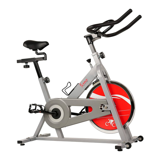
- Page 1 INDOOR CYCLING BIKE SF-B1001S USER’S MANUAL IMPORTANT! Please read this manual carefully before using this product. Retain owner’s manual for future reference. For Customer Service, please contact: support@sunnyhealthfitness.com...
-
Page 2: Important Safety Information
IMPORTANT SAFETY INFORMATION We thank you for choosing our product. To ensure your safety and health, please use this equipment correctly. It is important to read this entire manual before assembling and using the equipment. Safe and effective use can only be assured if the equipment is assembled, maintained, and used properly. -
Page 3: Exploded Drawing
EXPLODED DRAWING... -
Page 4: Parts List
PARTS LIST Part No. Description Part No. Description Main frame Phillips tapping screw Front stabilizer Hex nut M10 Rear stabilizer Water bottle holder Handlebar Nylon nut Seat post Foam grip Seat slider Saddle Allen bolt Pop-pin knob Spring washer 9L/R Pedal 25 A/B Handlebar cover... - Page 5 ASSEMBLY INSTRUCTIONS STEP 1: Attach the Front Stabilizer (No. 2) and Rear Stabilizer (No. 3) to the Main Frame (No. 1) with 4 Bolts (No. 14) and 4 Flat Washers (No. 13). Tighten and secure with Allen Wrench (A). Make sure the Foot Levelers (No. 11) are on the bottom and the transportation wheels facing up at the front of the bike.
- Page 6 STEP 2: Attach the Handlebar (No. 4) to the Handlebar Post (No. 26) using 4 Allen bolts (No. 23), 4 Flat Washers (No. 13) and 4 Spring Washers (No. 24). Tighten and secure with Allen Wrench (A). Set the Lower Handlebar Cover (No. 25B) on the square tube of the Handlebar Post (No. 26) in alignment with the four grooves on the mouth.
- Page 7 STEP 3: Lock the Saddle (No. 7) onto the Seat Slider (No. 6) tightly. Adjust the saddle to the desired position by sliding it on Seat Slider (No. 6) then lock the Seat Slider (No. 6) on the Seat Post (No. 5) with Pop-pin Knob (No. 8). Insert the Seat Post (No. 5) to the rear upright tube of Main frame (No.
-
Page 8: Operational Instructions
OPERATIONAL INSTRUCTIONS LEVELING THE BIKE This bike can be leveled to compensate for uneven grounding. To level the bike, please raise or lower the Foot Levelers (No. 11) located under the Front and Rear Stabilizers (No. 2 & No. 3). RESISTANCE ADJUSTMENT The pedal resistance is controlled by the tension control knob. -
Page 9: Handlebar Adjustment
HANDLEBAR ADJUSTMENT Loosen and pull the Pop-Pin (No. 8) out, then raise or lower the Handlebar (No. 4) to the desired position. Make sure the pop- pin settles into the desired hole and secure firmly. PEDAL STRAP ADJUSTMENT Place the ball of each foot in the toe clip until the front of the shoe fits into the toe clip cage.
Need help?
Do you have a question about the SF-B1001S and is the answer not in the manual?
Questions and answers