
Related Manuals for Kistler 9345B


Summary of Contents for Kistler 9345B
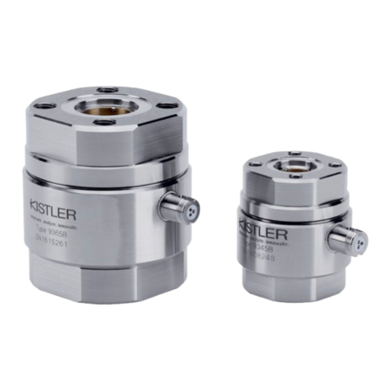
- Page 1 Instruction Manual 2-Component Sensor Type 9345B, 9365B 9345B_002-553e-03.23...
- Page 3 Information in this document is subject to change without notice. Kistler reserves the right to change or improve its products and make changes in the content without obliga- tion to notify any person or organization of such changes or improvements.
-
Page 4: Table Of Contents
Notes on Using the 2-Component Sensor ................6 General Description ........................7 What is the Purpose of the 2-Component Sensor? ............. 7 Design and Functional Principle of the 2-Component Sensor Type 9345B and 9365B ..8 Installation and Startup ......................9 Important Information ...................... 9 Installation of the 2-Component Sensor ................ - Page 5 2-Component Sensor Type 9345B, 9365B ............... 47 Dimensions Type 9345B and 9365B ................49 Dimensions Included Accessories ..................50 8.3.1 Centering Ring for Type 9345B and 9365B ............50 Dimensions of Accessories (Optional) ................51 8.4.1 Flange for Type 9345B and 9365B ..............51 Accessories Included .......................
-
Page 6: Introduction
It will help you with the installation, maintenance, and use of this product. To the extent permitted by law Kistler does not accept any liability if this instruction manual is not followed or prod- ucts other than those listed under Accessories are used. -
Page 7: Important Notes
Important Notes 2. Important Notes It is essential for you to study the following notes, which are for your personal safety during work, and to ensure long term, fault-free operation of this product. For Your Safety This product has been thoroughly tested and has left the factory in a perfectly safe condition. -
Page 8: Unpacking
2-Component Sensor Fz, Mz, Type 9345B, 9365B Unpacking Check all packaging for transport damage. Report any such damage to the transporters and to the authorized Kistler distributor. Check accessories delivered (see Section 8.5) before first use of the equipment. Report any missing parts to the au- thorized Kistler distributor. -
Page 9: General Description
Testing of screw caps The hole pattern of the bilaterally integrated flange and the optional accessories enable Kistler 2-component sensors to be adapted to almost any task. Bilateral centering seats and the included centering rings assist in the precise axial appli- cation of torque. -
Page 10: Design And Functional Principle Of The 2-Component Sensor Type 9345B And 9365B
2-Component Sensor Fz, Mz, Type 9345B, 9365B Design and Functional Principle of the 2-Component Sensor Type 9345B and 9365B The special patented design of Kistler 2-component sensors is characterized in that the sensor is axially preloaded. Par- ticularly in the case of small forces and moments, this pre- loading of the sensor is a requirement for good linearity of the output signal. -
Page 11: Installation And Startup
Installation and Startup 4. Installation and Startup Important Information The 2-component sensor Types 9345B and 9365B are pre- cision instruments whose specifications are fully utilized on- ly when they are correctly employed and only when they are carefully handled. Please comply with the following: ... - Page 12 2-Component Sensor Fz, Mz, Type 9345B, 9365B The force and moment must only be applied by the flange surfaces at the top and bottom sides of the 2-component sensor. The force is thereby transferred via the front-side flanged-on adaptation parts (strength class at least 12.9) or mounting parts with appropriate contact surfaces.
-
Page 13: Overview Of Adaptation Possibilities Type 9345B And 9365B
In particular, the greatest care must be exercised in dirty environmental conditions. Overview of Adaptation Possibilities Type 9345B and 9365B Punch 2-Component Sensor... - Page 14 2-Component Sensor Fz, Mz, Type 9345B, 9365B Mounting in Press Punch Installation in shaft with adapter for shaft journal with pin Shaft Installation Adapter for straight bore recess with pin Fig. 5: Mounting in press punch Mounting in Press Ram...
- Page 15 Installation and Startup Table Mounting Fig. 7: Table mounting These mounting possibilities are described in the following pages. 9345B_002-553e-03.23 Page 13...
-
Page 16: Adaptation A: Installation In Shaft With Adapter For Shaft Journal With Pin
2-Component Sensor Fz, Mz, Type 9345B, 9365B 4.3.1 Adaptation A: Installation in Shaft with Adapter for Shaft Journal with Pin Adapter for shaft journal with pin Installation clearance S Pinned during installation Centering rings (included accessories) Adapter for cylinder bore recess with pin... - Page 17 Centering rings (Art.-No. 3.420.180/181) on 2-compo- nent sensor into the centering bores on the reaction torque sensor up to the mechanical limit stop. Tightening torques M for socket head screws Type 9345B M5x12 = 4 N·m Type 9365B M8x20 = 21 N·m...
-
Page 18: Adaptation B: Installation In Shaft With Adapter Flange
2-Component Sensor Fz, Mz, Type 9345B, 9365B 4.3.2 Adaptation B: Installation in Shaft with Adapter Flange Customized centering ring (g6) Adapter flange for flat mounting in Installation shaft clearance S Customized center- ing ring (g6) Fig. 9: Mounting example B Compression force [N] = Torque [N·m]... - Page 19 Centering rings (customer specific, fit g6) press into the centering bores on the 2-component sensor up to the me- chanical limit stop. for socket head screws Tightening torques M Type 9345B M5x12 = 4 N·m Type 9365B M8x20 = 21 N·m...
-
Page 20: Adaptation C: Installation In Shaft With Integrated Flange
2-Component Sensor Fz, Mz, Type 9345B, 9365B 4.3.3 Adaptation C: Installation in Shaft with Integrated Flange Installation clearance S Centering pin g6 on customized shaft Installation clearance S Fig. 10: Mounting example C Compression force [N] = Torque [N·m] Applied via shaft with integrated flange and center- ing pin. - Page 21 Installation and Startup Tightening torques M for socket head screws Type 9345B M5x12 = 4 N·m Type 9365B M8x20 = 21 N·m We recommend using screws with at least property class 12.9, see also Section 4.2. Clearance S between the end of the mounting screw and the base of the threaded blind bore in the flange of the 2-component sensor.
-
Page 22: Adaptation D: Deep Drawing Tool With Centric Ejection Tool
2-Component Sensor Fz, Mz, Type 9345B, 9365B 4.3.4 Adaptation D: Deep Drawing Tool with Centric Ejection Tool Work piece Deep drawing tool Customized Mounting centering rings clearance S Ejection tool Customized table mount- ing (counter-sunk) Customized ejection tool Fig. 11:... -
Page 23: Adaptation E: Punch With Centric Ejection Bore
The maximum permissible values are listed in the table in the "Technical data" on page 48 (shear force max. F Tightening torques M for fillister-head screws Type 9345B M5x12 = 4 N·m Type 9365B M8x20 = 21 N·m We recommend the use of screws from strength class 12.9 upwards, see also section 4.2. -
Page 24: Adaptation F: Riveting Tool
2-Component Sensor Fz, Mz, Type 9345B, 9365B 4.3.6 Adaptation F: Riveting Tool Riveting tool Toolholder Customized table Mounting mounting clearance S Fig. 13: Mounting example F Compressive force [N] = Torque [N·m] Applied via riveting tool Transverse force [N] This "disturbance force" represents the shear forces and bending moments acting on the reaction torque sensor. -
Page 25: Adaptation G: Adapter Flange For Wrenches With External Square Head
Centering rings (Art.-No. 3.420.180/181) press into the centering bores on the 2-component sensor up to the mechanical limit stop. Tightening torques M for socket head screws Type 9345B M5x12 = 4 N·m Type 9365B M8x20 = 21 N·m We recommend using screws with at least property class 12.9, see also section 4.2. -
Page 26: Adaptation H: Screw Plate With Spring Assembly
2-Component Sensor Fz, Mz, Type 9345B, 9365B 4.3.8 Adaptation H: Screw Plate with Spring Assembly Test screw Spring assembly Customized screw plate Centering rings Installation (included accessories) clearance S Customized mounting plate Fig. 15: Mounting example H Compressive force [N] = Torque [N·m]... -
Page 27: Adaptation I: Desktop Installation With Mounting Flange
Installation and Startup 4.3.9 Adaptation I: Desktop Installation with Mounting Flange Installation Centering ring clearance S (included accessories) Mounting flange Type 9580A… (optional accessories) Fig. 16: Mounting example I Compression force [N] = Torque [N·m] Applied via standard flange adaptation Transverse force [N] This "disturbance force"... - Page 28 2-Component Sensor Fz, Mz, Type 9345B, 9365B Centering rings (Art.-No. 3.420.180/181) press into the centering bores on the 2-component sensor up to the mechanical limit stop. Tightening torques M for socket head screws Type 9345B M5x12 = 4 N·m...
-
Page 29: Basic Circuit And Cabling Of The Measuring Chain
We recommend that the two connectors on the connec- ting cable are cleaned before connection using the clean- ing and insulation spray Type 1003 from Kistler or white spirit. The connector on the 2-component sensor is sealed with an O-ring. With some cables, this is enclosed sepa- rately and must be installed before using the connector. - Page 30 2-Component Sensor Fz, Mz, Type 9345B, 9365B The following illustration shows the elements required to connect the 2-component sensors to a charge amplifier such as charge amplifier (e.g. Type 5015A). Calibration Measuring Chain Comprising 2-component sensor, cable and charge amplifier Type...
-
Page 31: Operation
Operation 5. Operation Setting the Charge Amplifier In conjunction with the 2-component sensors Type 9345B and 9365B we recommend the use of a charge amplifier with sensitivity selection such as Type 5073A... or a ControlMonitor Type 5863A..Details for equipment set up are given in the relevant instruction manuals. -
Page 32: Resolution Of The Measuring Signal
In the case of industrial charge amplifiers, the resolution with the highest gain is typically ± In combination with the sensitivity of the Press Force Sen- sor such as Type 9345B: –3,7 pC/N) the resolution amounts to: ± ±... - Page 33 The time during which so-called quasistatic measurements can be carried out is determined by the accuracy required. The value for the sensitivity of the sensor such as Type 9345B: –3,7 pC/N) can be used to estimate the drift in mechanical units. 0,05 pC/s ±...
- Page 34 2-Component Sensor Fz, Mz, Type 9345B, 9365B A measurement of 10 minutes duration therefore results in a drift of: − ⋅ ⋅ N·m/s 0,16 N·m This absolute error is viewed in relation to the measured value; for example, with 10 N·m torque it amounts to 1,57 %.
-
Page 35: Calibration And Maintenance
If it is possible to remove the force measurement assembly, without influencing the pretension and load distributing of the force sensor, the assembly can be sent to a Kistler Cali- bration Center for recalibration. If, however, the sensor is integrated into the machine structure, it normally is not possible to remove the force measurement assembly for re- calibration. -
Page 36: Test System Requirements
2-Component Sensor Fz, Mz, Type 9345B, 9365B 6.1.1.1 Test System Requirements Reference measurement chain: The reference measurement chain consists of a calibrated pre-loaded 2-component sensor and charge amplifier. Signal conditioning: The signal readout devices for both the reference and test systems must be equipped with peak-hold func- tionality. -
Page 37: Load Application
Calibration and Maintenance 6.1.1.3 Load Application A typical load cycle is shown in Fig. 20. 1. The system must be in an unloaded condition to define the zero force bias; 2. Reset the charge amplifiers and, if necessary, the peak hold functions for both the reference and test system measurement channels. -
Page 38: Calibration Process Worksheet
2-Component Sensor Fz, Mz, Type 9345B, 9365B 6.1.1.4 Calibration Process Worksheet Set up the charge amplifier for the maximum range of the reference sensor and the corresponding sensitivity as shown on the calibration certificate. Range: [MU] Sensitivity: Cal. Cert. [pC/MU] REF(F Set up the test system amplifier to approximately determine the charge output of the test sensor. - Page 39 Calibration and Maintenance Apply load at the working point at least 5 times, note the peak values from both the reference and test systems for each cycle. F ˆ [MU] Q ˆ [pC] Calculate the peak sensitivity for each cycle. Q ˆ...
-
Page 40: Working Point Calibration By Peak Value Comparison For M
2-Component Sensor Fz, Mz, Type 9345B, 9365B 6.1.2 Working Point Calibration by Peak Value Comparison for M The test system is calibrated by comparing its output with that of a reference measurement chain at loads around a specific working point. An average sensitivity is calculated from the peak values of both the reference and test sys- tems recorded over multiple load cycles. -
Page 41: Reference 2-Component Sensor (2Cs) Installation
Calibration and Maintenance 6.1.2.2 Reference 2-Component Sensor (2CS) Installation Place the reference 2-component sensor directly in the force path of the test system as shown in Fig. 23. Always make use of force distribution caps or spherical washers and ensure that the test force is applied centrically through the reference PFS. - Page 42 2-Component Sensor Fz, Mz, Type 9345B, 9365B Test system [pC] Charge signal [pC] Measurement range (Full Scale) for test sys- tem charge amplifier [pC] Test system output for load cycle i UUTi Q ˆ [pC] Peak value displayed on the test system...
-
Page 43: Calibration Process Worksheet
Calibration and Maintenance 6.1.2.4 Calibration Process Worksheet 1. Set up the charge amplifier for the maximum range of the reference sensor and the corresponding sensitivity as shown on the calibration certificate. Range: [MU] Sensitivity: Cal. Cert. [pC/MU] REF(M 2. Set up the test system amplifier to approximately determine the charge output of the test sensor. For the first iteration, use the maximum range of the charge amplifier. - Page 44 2-Component Sensor Fz, Mz, Type 9345B, 9365B 6. Apply load at the working point at least 5 times, note the peak values from both the reference and test systems for each cycle. M ˆ [MU] Q ˆ [pC] 7. Calculate the peak sensitivity for each cycle.
- Page 45 Calibration and Maintenance Fig. 23: In-situ calibration procedure (here: for force) 9345B_002-553e-03.23 Page 43...
-
Page 46: Kistler Calibration Service
Kistler offers the following calibra- tion services: Swiss Calibration Service (SCS) Kistler is accredited as SCS Calibration Center No. 049 for equipment measuring pressure, force, acceleration and electrical charge. To ensure traceability and specified measurement uncertainties, calibration equipment and methods are regularly monitored and audited. -
Page 47: Troubleshooting
7. Troubleshooting Fault-Finding and Remedy Below is a list of the frequent causes of malfunction and in- structions on how to remedy these. If a fault occurs which you cannot correct, please contact your Kistler distributor. Fault Cause Remedy No measuring signal at the... -
Page 48: Repairing The 2-Component Sensor
In the event of any necessary major repairs, you will receive a cost estimate. Kistler will attempt to repair your 2-component sensor in the shortest possible time at minimal cost and return it to you in an as-new condition. -
Page 49: Technical Data
Technical Data 8. Technical Data Please note that all technical data and all further infor- mation in this section can be changed at any time without prior notice. 2-Component Sensor Type 9345B, 9365B Type 9345B 9365B Measuring range, –10 ... 10 –20 ... - Page 50 2-Component Sensor Fz, Mz, Type 9345B, 9365B Rigidity , ≈1,7 ≈2,8 kN/µm ≈0,19 ≈0,92 N·m/µrad ϕ Natural frequency, >41 >33 >32 >25 Operating temperature °C –40 … 120 –40 … 120 Temperature coefficient of sensitivity, %/°C –0,02 –0,02 %/°C –0,01 –0,01...
-
Page 51: Dimensions Type 9345B And 9365B
Technical Data Dimensions Type 9345B and 9365B Fig. 24: Dimensional drawing 2-Component Sensor Type 9345B and 9365B Dimensions in mm Type 9345B 21,7 48,3 0,15 0,35 9365B 56,5 31,8 0,15 * Free passage with mounted centering swrings 9345B_002-553e-03.23 Page 49... -
Page 52: Dimensions Included Accessories
2-Component Sensor Fz, Mz, Type 9345B, 9365B Dimensions Included Accessories 8.3.1 Centering Ring for Type 9345B and 9365B Sensor Type Art. No. 9345B 3.420.180 9365B 3.420.181 *) Free access with mounted centering rings Page 50 9345B_002-553e-03.23... -
Page 53: Dimensions Of Accessories (Optional)
Technical Data Dimensions of Accessories (Optional) 8.4.1 Flange for Type 9345B and 9365B Type 9580A1/A2 for Type Type d1 d2 d4 d5 d6 H2 T1 9345B 55 14 6,6 5,3 12 9580A1 9365B 9580A2 100 78 21 13,5 8,4 18 14 22 9345B_002-553e-03.23... -
Page 54: Accessories Included
2-Component Sensor Fz, Mz, Type 9345B, 9365B Accessories Included Ordering Key Type Scope of Delivery including Accessories 2-Component Sensor 9345B 2 x cable clip 5.210.570 2 x screw 6.120.021 2 x centering ring 3.420.180 2-Component Sensor 9365B ... -
Page 55: Annex
The capacitance, and thus the length of the connecting cable, has no influence on the measuring result when Kistler special cables and Kistler charge amplifiers are used. Measuring range or part of the measuring range for which Calibrated measuring range the sensor has been calibrated. - Page 56 2-Component Sensor Fz, Mz, Type 9345B, 9365B Disturbance Forces, moments and environmental influences acting on the sensor such as the temperature, which the sensor does not measure as a measurand and which produce an output signal (error). Example: when an additional bending mo- ment acts on a force sensor.
- Page 57 See "Coulomb". pC (picocoulomb) piezoelectric Characteristic of quartz crystals in which mechanical load- ing produces a proportional electric charge. Describes the ability of Kistler sensors and charge amplifiers quasistatic to undertake short-term measurements or DC-similar mea- surements. see "Measuring range"...
-
Page 58: Measurement Uncertainty
2-Component Sensor Fz, Mz, Type 9345B, 9365B Measurement Uncertainty Systematic Errors, Accuracy Accuracy is the extent of the conformity between a meas- ured value and a true value of the measurand. In a piezoe- lectric measuring chain it is determined by many systematic errors, e.g. -
Page 59: Linearity
Errors due to zero drift caused by influence quantities changing with time, such as the temperature, are thus basically excluded. With Kistler piezoelectric measuring chains, a typical repea- tability within 0,1 % FSO can be assumed. Linearity... - Page 60 2-Component Sensor Fz, Mz, Type 9345B, 9365B Best Straight Line – Mathematical Definition The minimization of maximum deviation is known as Che- byshev’s approximation. The best straight line is deter- mined as follows: x = measurand (reference) Q = sensor charge signal or output signal from the charge amplifier ...
-
Page 61: Frequency Range
Annex Frequency Range Because of their mechanical quality, piezoelectric sensors have very low damping. The useful frequency range is limi- ted in the upwards direction by the increasing resonance rise. Key: f Measuring frequency Natural frequency Amplitude ratio The following approximate values apply to the amplitude error or achievable accuracy as a function of frequency: ≈... -
Page 62: Influence Of Temperature
2-Component Sensor Fz, Mz, Type 9345B, 9365B In their dynamic behavior, piezoelectric sensors are superior to all other measuring methods. Their high rigidity results in the highest possible natural frequencies. Piezoelectric sensors are thus ideal for measuring measurands which change rapidly over time. Their dynamic behavior is there- by largely determined by the surrounding structure. - Page 63 Annex Temperature Gradient Error (Dynamic Error) A temporary change in the output signal is denoted as temperature gradient error, when the temperature of the environment or surrounding medium changes with a cer- tain rate. In this case, the sensor is not in thermal equili- brium with the environment.
-
Page 64: Index
2-Component Sensor Fz, Mz, Type 9345B, 9365B Index Accuracy ..........56, 59 Linearity ............54 Adaptation ...........11 Application .............7 Measurand ...........54 Measuring chain ........27, 54 Bending moment ........9, 47 Measuring range ........47, 54 Measuring Range ..........29 Measuring uncertainty ........56 Cable ............11... - Page 65 Error! Use the Home tab to apply Überschrift 1 to the text that you want to appear here. Systematic errors .......... 56 Transport damage .......... 6 Technical data ..........47 Unpacking ............. 6 Temperature coefficient..... 48, 55, 61 Temperature error ........60 Temperature gradient error......
Need help?
Do you have a question about the 9345B and is the answer not in the manual?
Questions and answers