
Subscribe to Our Youtube Channel
Related Manuals for Kistler CHFA Series


Summary of Contents for Kistler CHFA Series
- Page 1 Instruction Manual HF Sensors Optical Laser Height Sensors Type CHFA… CHFA_002-583e-08.12...
- Page 2 Instruction Manual HF Sensors Optical Laser Height Sensors Type CHFA… CHFA_002-583e-08.12...
- Page 4 Information in this document is subject to change without notice. Kistler reserves the right to change or improve its products and make changes in the content without obligation to notify any person or organization of such changes or improvements.
-
Page 5: Table Of Contents
Content Content Introduction ........................... 4 Important Notes ..........................5 For Your Safety ........................5 Disposal Instructions for Electrical and Electronic Equipment ..........7 Software Upgrades and Updates ..................7 Product Overview .......................... 8 General Description ......................8 Features ..........................9 Application ........................... - Page 6 Content Troubleshooting ........................... 38 Cables and Power Supply ....................38 Protection Glass ........................38 Operating Range ........................ 38 Software ..........................38 CAN ............................ 39 Environmental Conditions ....................39 Service ..........................39 Appendix ............................40 Total pages: 40 CHFA_002-583e-08.12 Page 3...
-
Page 7: Introduction
It will help you with the installation, maintenance, and use of this product. To the extent permitted by law Kistler does not accept any liability if this instruction manual is not followed or products other than those listed under Accessories are used. -
Page 8: Important Notes
2. Important Notes 2.1 For Your Safety Please read carefully before operating the equipment. Kistler is not responsible for damage that may occur when this system is used in any way other than that for which it is intended. To assure safe and proper operation, all supplied... - Page 9 If it is necessary to make cables, always note correct pin. Kistler assumes no liability for damages caused due to the use of cables other than delivered by Kistler. Disconnect power from the sensor if the vehicle is stationary for extended periods.
-
Page 10: Disposal Instructions For Electrical And Electronic Equipment
Kistler Instrument sales office for return instructions. 2.3 Software Upgrades and Updates Kistler may from time to time supply upgrades or updates for embedded software. Such upgrades or updates must always be installed. Kistler declines any liability whatsoever for any direct or... -
Page 11: Product Overview
Optical Laser Height Sensors Type CHFA… 3. Product Overview 3.1 General Description HF laser height-sensors are designed for non-contact distance measurement for vehicle dynamics testing. Laser height-sensors of the HF series use the principle of optical triangulation. A visible red laser is focused onto the road surface. -
Page 12: Features
Further fields of application are for instance uplift measurements, spring deflection, dynamic tire flat spotting, tire lift-off (Fishhook Test). Two HF sensors mounted at the wheel enable dynamic camber angle measurement (refer to the Kistler DCA System). 3.4 Accessories Included Accessories Type/Art. -
Page 13: Technical Data
Optical Laser Height Sensors Type CHFA… 4. Technical Data 4.1 Specifications Performance Specifications HF-250C HF-500C HF-750C Measurement range 100 ... 350 125 ... 625 150 ... 900 Resolution Linearity ±0,2 ±0,2 ±0,3 Sampling rate 0,3 … 8 Light source Laser Laser class 3R (IEC608251) Laser power... -
Page 14: Pin Assignments
Technical Data 4.2 Pin Assignments Sensor connector, analog/digital, 9 pin MIL, male Signal CAN+ CAN– Shield Signal 9 … 18 V Signal cable, 1 m 8 pin Binder with cable to 6 pin Lemo Signal n.c. 12 V n.c. Signal Signal cable, 1 m 8 pin Binder with cable to BNC and 2x4 mm bunch pin plug Bunch pin plug black... - Page 15 Optical Laser Height Sensors Type CHFA… RS-232C output cable, 1 m 8 pin Binder with cable to 9 pin D-Sub and 2x4 mm bunch pin plug Bunch pin plug black Bunch pin plug red 12 V Signal 10 k with pin 7 n.c.
-
Page 16: Sensor Settings
Technical Data 4.3 Sensor Settings The following parameters can be set with the help of CeCalWin Pro. 4.3.1 Average Time Due to the high sampling rate and the small measuring spot, the sensor signal may be quite rough on uneven surfaces but it is possible to smoothen the signal by using a moving average filter. -
Page 17: Setup And Connection
Optical Laser Height Sensors Type CHFA… 5. Setup and Connection 5.1 Mounting Options DCA System Fig. 2: Possible mounting positions In wet or snowy conditions, please mount the sensor at the front of the vehicle. This will help to prevent measurement anomalies that can be caused by spray and/or blowing snow. - Page 18 Setup and Connection To achieve optimum performance and accuracy, the mounting distance from the lower surface of the sensor body (not including the spray guard) to the road surface must be within the specified range (see chapter 4.1 Specifications). sensor body HF-250C: 100 …...
-
Page 19: Sensor Mounting Jig
Optical Laser Height Sensors Type CHFA… 5.2 Sensor Mounting Jig Mounting surface Please keep free from stickers or labels! Fig. 4: Sensor dimensions The electronic unit is equipped with reverse polarity protection. In the event that polarity is inverted, the unit will not be damaged. -
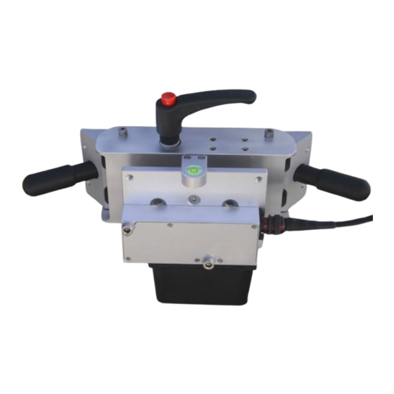
Page 20: Mounting Instructions
Setup and Connection 5.3 Mounting Instructions 5.3.1 Installation with Suction Holder Locking lever Top: Stabilizer element Bottom: Suction holder unit Locking lever Locking lever Suction holder Suction holder Level indicator Pumping piston Sensor mounting plate Fig. 5: 3-point suction holder HF, Art. No. KCD15408 To assure proper function of the suction holders, the mounting area must be free of grease, oil, dust and other contaminants. - Page 21 Optical Laser Height Sensors Type CHFA… Fig. 6: Assembling stabilizer element and suction holder unit Assemble the suction holder unit and the stabilizer element. Fig. 7: Removing the protection caps Remove the protections caps and place the complete suction holder unit at the vehicle body so that it will be within the required measuring range (see Chapter 4.1, Specifications).
- Page 22 Setup and Connection Fig. 8: Pushing the pumping piston When the suction holder unit is correctly positioned, press the suction holders – one after the other – firmly against the vehicle body to flatten the rubber pads against the body surface. Then, push the two pumping pistons repeatedly until the red warning ring is not visible any more.
- Page 23 Optical Laser Height Sensors Type CHFA… Monitor the pumping pistons during use to be sure that the suction pads adhere firmly! If the red warning ring is going to become visible, the suction pads are going to loosen. In this case please interrupt use and push the pistons until the red ring is invisible again.
- Page 24 Setup and Connection Fig. 11: Mounting the sensor Attach the HF sensor to the mounting plate. Insert the sensor mounting screws through the mounting holes in the sensor, then into the holes of the mounting plate and tighten the screws with an allen wrench (size 4 mm). It is definitely recommended to use the polyamid washers (also included in the scope of delivery).
- Page 25 Optical Laser Height Sensors Type CHFA… Fig. 13: Affixing the safety line Wind the safety line around the stabilizing element and mount the metal clamp. We recommend to protect the painted surface in this area with an easy-to-remove tape and to remove it right after the measurement.
- Page 26 Setup and Connection Fig. 15: Securing the safety line (at the window in this case) Fig. 16: Connecting the sensor Connect the signal cable to the sensor and route it into the interior of the car to the sensor electronics unit. Use cable ties to fix the signal cable at the mounting unit.
- Page 27 Optical Laser Height Sensors Type CHFA… Fig. 17: HF sensor, completely mounted with magnet holder at the rear passenger door Now, your HF sensor ready for use! Page 24 CHFA_002-583e-08.12...
-
Page 28: Installation With Magnet Holder
Setup and Connection 5.3.2 Installation with Magnet Holder Locking lever Magnet Magnet Magnet release device Level indicator Sensor mounting plate Magnet release device Fig. 18: 4 point magnet holder HF, Art. No. KCD15213 You can install the magnetic plate holder HF either horizontal or vertical. - Page 29 Optical Laser Height Sensors Type CHFA… Fig. 20: Placing the magnet holder Take the pre-assembled magnetic plate holder and place it parallel to the vehicle body (e.g. at the rear passenger door as shown above). The magnetic plates will automatically hold fast to the (metal) vehicle door/body panel.
- Page 30 Setup and Connection Fig. 22: Mounting the sensor Attach the HF sensor to the mounting plate. Insert the sensor mounting screws through the mounting holes in the sensor, then into the holes of the mounting plate and tighten the screws with an allen wrench (size 4 mm). It is definitely recommended to use the polyamid washers (also included in the scope of delivery).
- Page 31 Optical Laser Height Sensors Type CHFA… Fig. 24: Connecting the sensor Connect the signal cable to the sensor and route the cable into the interior of the vehicle to the sensor electronics device and connect it there too. Now, your HF sensor ready for use! In most cases it will not be necessary to use a safety line as the magnets hold automatically fast to the (metal) vehicle body.
-
Page 32: Installing The Safety Line
Setup and Connection 5.3.3 Installing the Safety Line Fig. 25: Wind the safety line around stabilizer rod 2 Fig. 26: Mount the metal clamp CHFA_002-583e-08.12 Page 29... - Page 33 Optical Laser Height Sensors Type CHFA… Fig. 27: Adjust the length of the safety line Fig. 28: Secure the safety line (at the window in this case) Pay attention that the metal clamp of the safety line cannot come into contact with the painted surface of the vehicle body! Page 30 CHFA_002-583e-08.12...
-
Page 34: Connecting The Sensor
Setup and Connection 5.4 Connecting the Sensor 5.4.1 Connecting the Sensor to a Data Acquisition System Connect the signal/power cable (Art. No. KCD14760) to the sensor Connect the signal cable (Art. No. KCD14992 or KCD14993 or KCD15622) to the signal/power cable Connect the BNC plug to the analog input or the D-Sub plug to a CAN input of the data acquisition system Connect the banana plugs to an adequate power... -
Page 35: Sensor-Specific Software Description
Optical Laser Height Sensors Type CHFA… 6. Sensor-specific Software Description 6.1 Project Window Settings HF Sensors Within the Project Window, three tabbed sections will be displayed: Measurement Display, Filter, and CAN-Bus. Options for system configuration, operation and data display are explained in the following pages. 6.1.1 Measurement Display The "Measurement Display"... -
Page 36: Filter
Sensor-specific Software Description 6.1.2 Filter The Filter tab enables adjustment of the filter mode setting for a connected HF sensor. Fig. 30: Screen view "Filter" Filter Mode Select the checkbox to activate access to the average time setting for the connected distance sensor. Average Time: user-selectable (default value = 1) Other values can be entered manually, or by using the scroll/edit field. -
Page 37: Can-Bus
Optical Laser Height Sensors Type CHFA… 6.1.3 CAN-Bus Here you can configure the CAN bus according to your requirements. For further information on the CAN bus, please refer to chapter 6.2, CAN Protocol. Fig. 31: Screen view "CAN-Bus" Baud rate (Default value = 1 Mbaud): Sets the commu- nication baud rate for the CAN Protocol. -
Page 38: Can Protocol
Sensor-specific Software Description 6.2 CAN Protocol Version 1.0 03.09.2007 There are 2 modes of data transmission on the CAN-Bus. The transmission mode can be selected using CeCalWin Pro Software. The CAN messages sent by the sensors for all modes consist of one or more frames (a frame is defined in the CAN-Bus specifications). -
Page 39: Definitions Of The Frame
Optical Laser Height Sensors Type CHFA… 6.2.1 Definitions of the Frame The definitions here present how the data bytes within a CAN message frame are allocated in order to decipher the data transmitted. Data Frame Format: 8 Data bytes Default ID (Standard) : 0x7FF Default ID (Extended): 0x1FFFFFFF Data byte Description... -
Page 40: Generating Can Database Files (Candb)
Sensor-specific Software Description 6.3 Generating CAN Database files (CanDB) From CeCalWin Pro Version 1.9 on, it is possible to create CAN database files. To start the generation of CAN data- base files, please select Options > Create CanDB. Fig. 33: Screen view "Create CanDB", 1 After selecting this menu item, you will be prompted to choose a location for storing the CAN database file. -
Page 41: Troubleshooting
Optical Laser Height Sensors Type CHFA… 7. Troubleshooting 7.1 Cables and Power Supply Check all connections to determine that each is complete and that the system is connected to a power supply that provides voltage output within the specified range Check to determine that the correct cables have been used for all connections The following problem can be caused by incorrect or... -
Page 42: Can
The serial numbers of all relevant components With a HF sensor you have purchased a premium, high-precision product. To assure continued optimum performance, we recommend that you send it to Kistler once per year for inspection, maintenance, and calibration. CHFA_002-583e-08.12... -
Page 43: Appendix
Optical Laser Height Sensors Type CHFA… 8. Appendix Technical Drawing HF Sensor Laser axis ® Correvit is a registered trademark of Kistler Holding AG Page 40 CHFA_002-583e-08.12...
Need help?
Do you have a question about the CHFA Series and is the answer not in the manual?
Questions and answers