Table of Contents
Advertisement
Quick Links
Advertisement
Table of Contents

Related Manuals for AMS AS7030B


Summary of Contents for AMS AS7030B
- Page 1 User Guide UG000493 AS7030B User Manual Evalution Kit v1-00 • 2020-Jun-25...
-
Page 2: Table Of Contents
FW, Driver, API .......... 55 Hardware Architecture ......... 7 Power Supply ..........8 Revision Information ....62 AS7030B Overview ......9 Legal Information ......63 Optical Front End (OFE) ......9 ECG Amplifier ..........12 Electrical Analog Front End (EAFE) ... 14 Light-to-Frequency Converter (LTF) .. -
Page 3: Introduction
AS7030B Introduction Introduction The AS7030B Evaluation Kit allows evaluation of all functions on the AS7030B Biosensor and test them in various applications. The initial Evaluation Kit works with USB connection to the PC and comes with a GUI, which enables the user to change AS7030B register settings, see measurement results and many more. -
Page 4: Ordering Information
Document Feedback AS7030B Introduction Ordering Information Ordering Code Description AS7030B-EVALKIT Evaluation Kit for AS7030B AS7030B-WRISTBAND Wristband to connect to AS7030B Evalkit Demo Kit Manual • PUBLIC UG000493 • v1-00 • 2020-Jun-25 │ 4... -
Page 5: Getting Started
USB stick as a part of the evaluation kit. To install, start the installer executable and follow the instructions as shown in Figure 2 (left to right top to bottom). Figure 2: AS7030B Vital Signs Sensor Installation Demo Kit Manual • PUBLIC UG000493 • v1-00 • 2020-Jun-25... - Page 6 Document Feedback AS7030B Getting Started ® For Windows OS versions prior to Windows 10, the STSW-STM32102 virtual COM port driver needs to be installed as well. The driver can be found in the <drivers\STM32_vcp_driver> folder contained within the client software installation path. To install it, go to your OS version directory (Win7 or Win8, ®...
-
Page 7: Hardware Description
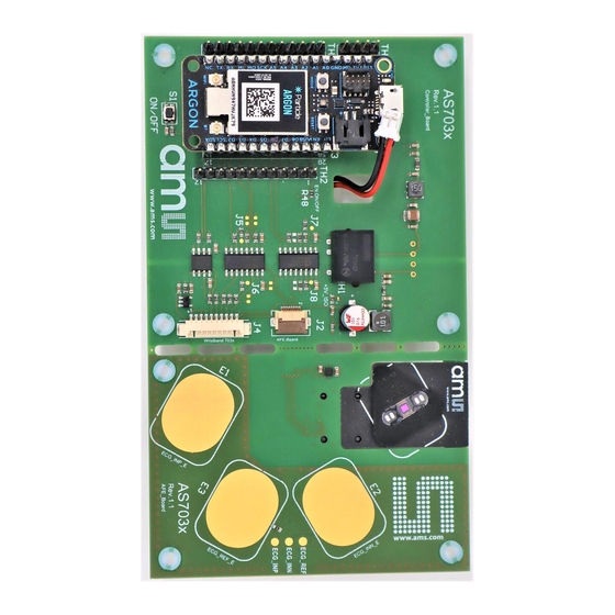
Document Feedback AS7030B Hardware Description Hardware Description Hardware Architecture Figure 3: Evaluation Hardware Board – Top View Current Interface IEC 60601 Consumption ECG INN Electrode Compilant DC-DC ADC ADS114 converter AS7030 Pin Header DFU Button Test Point for External ECG REF Electrode... -
Page 8: Power Supply
Break out Board Power Supply The AS7030B Eval Kit is supplied by the USB connection. In order to avoid a direct connection from the electrodes to the power grid, an IEC 60601-1 compliant RECOM DCDC converter (R0.25S-0505/H or R0.25S-0505/HP) is assembled on the board as well as isolator ICs for all signals passing to the sensor board. -
Page 9: As7030B Overview
AS7030B Overview AS7030B Overview The AS7030B is a photocurrent and voltage sensor capable of taking PPG, ECG, proximity and skin temperature/resistivity measurements. It integrates an optical front end, ECG amplifier, electrical analog front end and light to frequency (LTF) converter. It features a built-in sampling sequencer, 128- byte FIFO, a 14-bit SAR ADC, four GPIO pins and an I C interface. - Page 10 Document Feedback AS7030B AS7030B Overview The optical front end consists of: ● 4 LED drivers, individually configurable, operated manually or controlled by the built-in sampling sequencer ● 2 built-in green LEDs (VD1 and VD2) ● 1 built-in IR LED (VD4) ●...
- Page 11 Document Feedback AS7030B AS7030B Overview Trans-Impedance Amplifier (TIA) ● Configurable photodiode connection ● Photodiode input current offset compensation ● Configurable gain ● 2 different modes of operation – photocurrent to voltage converter or photocurrent integrator ● Clip detection Figure 7: Trans-Impedance Amplifier ●...
-
Page 12: Ecg Amplifier
Document Feedback AS7030B AS7030B Overview Figure 8: Optical Signal Conditioning Each of the blocks depicted on Figure 8 can be individually enabled or disabled/bypassed. ECG Amplifier The ECG (electro cardiogram) amplifier is a high impedance, low noise instrumentation amplifier with analog circuitry to band pass filter the signal. - Page 13 Document Feedback AS7030B AS7030B Overview Figure 9: ECG Amplifier Circuit ecg_low_leakage_en for diode leakage reduction on ECG_INP and ECG_INN AS7030_ECG_INP Leads off detect AS7030_ECG_INN ecg_ref_en AS7030_ECG_REF SIGREF to electrical frontend Figure 10: Recommended ECG Frontend Filter ECG_INP ECG_INN ECG_REF Demo Kit Manual • PUBLIC UG000493 •...
-
Page 14: Electrical Analog Front End (Eafe)
Document Feedback AS7030B AS7030B Overview Electrical Analog Front End (EAFE) The four general-purpose pins and ECG_REF can be used as analog input pins for the electrical analog front end. The analog inputs configuration sets up different non-inverting amplifier topologies: ●... -
Page 15: Light-To-Frequency Converter (Ltf)
Document Feedback AS7030B AS7030B Overview Light-to-Frequency Converter (LTF) The LTF module can use any of the photodiodes. Photodiodes connected to the LTF cannot be used at the same time with TIA. Integration time (itime) is configured in unit steps, one unit step is 3.702 ms. - Page 16 4.5.2 FIFO The AS7030B FIFO is 256 bytes long. ADC samples are 2 bytes each, which means, FIFO can hold up to 128 samples. There is a FIFO length register, which indicates how much samples are currently Demo Kit Manual • PUBLIC UG000493 •...
-
Page 17: Digital Interface
The sequencer executes measurement cycles with a period defined by Equation 1 where SEQ_PER and SEQ_DIV are registers of AS7030B having values from 0 to 255 (see pages 50 and 51 in the AS7030B datasheet): Equation 1: ������_������... - Page 18 Document Feedback AS7030B AS7030B Overview Within one sequencer cycle, the sequencer will: ● Switch on the LEDs at the specified LED start time and then switch them off at the LED stop time. ● Start the positive and negative synchronous modulator multiplications at the specified start and stop times for each operation ●...
- Page 19 Document Feedback AS7030B AS7030B Overview Figure 14: Sequencer Block Diagram 4.7.1 Sampling Rate and Subsampling Throughout this document, sampling rate refers to the rate at which the sequencer produces samples of the same ADC channel. This depends on the number of enabled ADC channels and on configuration of the subsampling feature of the sequencer.
- Page 20 Document Feedback AS7030B AS7030B Overview The register SEQ_CFG and SD_SUBS configure how subsampling will be executed: ● sd_subs field in SD_SUBS register defines if subsampling is enabled; when it is 0, no subsampling is done – every sequencer cycle triggers an ADC measurement (Figure 15);...
- Page 21 Document Feedback AS7030B AS7030B Overview Figure 15: No Subsampling (sd_subs=0) Figure 16: Subsampling of All Enabled ADC Channels (sd_subs=2 and sd_subs_always=1) Demo Kit Manual • PUBLIC UG000493 • v1-00 • 2020-Jun-25 │ 21...
- Page 22 Document Feedback AS7030B AS7030B Overview Figure 17: Subsampling of 1st Enabled ADC Channel Only (sd_subs=3 and sd_subs_always=0) Demo Kit Manual • PUBLIC UG000493 • v1-00 • 2020-Jun-25 │ 22...
-
Page 23: Software Description
Figure 18: SW Modules The AS7030B evaluation software consists of firmware and client software (GUI). The firmware runs on an ARM Cortex M4 MCU (STM32L476RETx), implements virtual COM port CDC interface for client communication and vital sign detection applications. The client software displays raw data, algorithm data and power consumption. - Page 24 AS7030B register, get FW number. Packs the responses to the incoming requests (when one is expected) and sends them to the CDC interface for transmission to the host.
- Page 25 Handles FW control requests like application selection, AGC configuration and measurement start/stop. Raw AS7030B Data Handler Collects and stores raw AS7030B sample data in a data buffer and sends the buffered data to the client upon request. Vital Sign Application Handlers – HRM, HRV and BP App Handlers Aggregates data needed by the relevant algorithm, runs the algorithm and handles data requests sent from the client.
- Page 26 Driver code used for AS7030B configuration (register read/write). Control Requests FW control requests – Start/stop measurements, select/deselect algorithm and AGC configuration. Register Map Direct access to the complete register set of the AS7030B. Demo Kit Manual • PUBLIC UG000493 • v1-00 • 2020-Jun-25 │ 26...
-
Page 27: Graphical User Interface
Handles incoming data – Updates the relevant ADC channel plot and/or updates vital sign data fields of the GUI. Graphical User Interface This section describes the Graphical User Interface (GUI) of the AS7030B Vital Sign Sensor application. The application is designed to be used with AS7030B sensor series evaluation kits. Information ●... - Page 28 Start/Stop recording Graphical representation of data Measurement type Calculated values based on measurement type Temperature (if sensor available) and current consumption (AS7030B) values The currently configured values for PD offset and Led input current Description of the current configuration Status box Connection status and FW version of connected hardware Demo Kit Manual •...
- Page 29 Document Feedback AS7030B Software Description 5.2.2 Powering Up and Starting a Measurement Connect the sensor board and the mainboard via the 10-pin Picoblade cable. Connect the micro USB to USB cable to the mainboard and plug it into your computer.
- Page 30 Software Description Select one of the built-in configuration presets Optionally check and change AS7030B settings. On the first startup after SW installation no settings are loaded, after that the last used settings will be used. To start a measurement with the current settings click on the Start button.
- Page 31 Document Feedback AS7030B Software Description The blood pressure measurement will give most accurate results with a personalized user profile. A default user profile is used, if no custom profile exists. To create a new user profile, open menu Settings and select “Open user data dialog”.
- Page 32 Document Feedback AS7030B Software Description Figure 25: Measurement of the Arterial Length Click “Save” to add the newly created user profile to the user profile database. Figure 26: Creating a New User Next step is to execute the calibration procedure in order to get the values for Systolic and Diastolic offsets.
- Page 33 Document Feedback AS7030B Software Description Calibration Procedure Select the user to calibrate from the “User name” combo box and click the “Calibrate” button. The caption of the “Calibrate” button will change to “Calibrating…”. Figure 27: User Calibration Blood pressure measurement will start. The “Start” button will turn to “Stop”, the PPG and ECG graphs will start plotting the raw data, and blood pressure values will start displaying on the “Main”...
- Page 34 Document Feedback AS7030B Software Description Figure 28: Calibration Ongoing After calculating the five blood pressure values successfully, calibration will be finished, the measurement is stopped and the values for “Systolic offset” and “Diastolic offset” are updated. Demo Kit Manual • PUBLIC UG000493 •...
- Page 35 Document Feedback AS7030B Software Description Figure 29: Calibration Finished Click “Set” to save the values and close the window. Demo Kit Manual • PUBLIC UG000493 • v1-00 • 2020-Jun-25 │ 35...
- Page 36 Software Description 5.2.4 AS7030B Configuration Settings The AS7030B configuration settings are located on the left of the evaluation software (see Figure 21). At power-up, the board starts with the following default configuration: ● The two green LEDS - LED1(VD1) and LED2(VD2) are enabled, the LED current set to 1 mA ●...
- Page 37 LED Driver Block Diagram For further information, please refer to the following document: ● AS7030B Datasheet page 24 ff Photodiodes Configuration Select the photodiodes which are to be connected to TIA input. The offset current is optional, this allows cancellation of constant light sources like sunlight. Default value for the input offset current is 0 Demo Kit Manual •...
- Page 38 AS7030B Datasheet page. 35ff. TIA (Trans-Impedance Amplifier) Configuration The TIA has to be configured according to the information in the AS7030B datasheet (table in figure 33. AS703x Block Diagram). It is recommended to keep the TIA settings at their default.
- Page 39 Document Feedback AS7030B Software Description Figure 36: Figure 37: TIA Configuration Submenu TIA Block Diagram For changing the TIA, stick to the following suggestions: Figure 38: TIA Suggestion pd_ampres pd1234 pd_ampcap pd_ampcomp pd_ampvo Gain 1…4 1 V/µA 1…4 2 V/µA 1…4...
- Page 40 … number of active photodiodes (for example, pd1=1, pd2=0, pd3=1, pd4=0 -> pd1234=2) For further information, please refer to the following document: ● AS7030B Datasheet page. 40 ff. Demo Kit Manual • PUBLIC UG000493 • v1-00 • 2020-Jun-25 │ 40...
- Page 41 The “Prefilter” tab is used to configure the input filters of the two synchronous demodulators. For reference, please see OFE_CFGA, OFE_CFGB, OFE_CFGC and OFE_CFGD register descriptions in the AS7030B datasheet. Demo Kit Manual • PUBLIC UG000493 • v1-00 • 2020-Jun-25...
- Page 42 AS7030B Software Description For further information, please refer to the following document: ● AS7030B Datasheet page. 47 ff … Sequencer Configuration Figure 41: Sequencer Configuration Submenu The “Cycle period” field of the “Sequencer configuration” window (see Figure 41) holds the value of the SEQ_PER register.
- Page 43 ADC channel selection will cause a new calculation of the values for the rest of the fields. For further information, please refer to the following document: AS7030B Datasheet page. 47 ff. ADC Configuration This window configures the clock divider of the 1 MHz ADC input clock and the ADC settling periods.
- Page 44 Document Feedback AS7030B Software Description For further information, please refer to the following document: ● AS7030B Datasheet page. 98 ff. Interrupts Configuration Enable interrupt sources: ● ADC: End of ADC conversion ● Sequencer: End of sequencer sequence reached. ● LTF: A light-to-frequency conversion is finished.
- Page 45 Document Feedback AS7030B Software Description This value scales up to a max of 1.6 V of offset at gain 1. An optional 50/60 Hz notch filter can be enabled to attenuate unwanted noise from mains coupling. The recommended gain settings are 4-6-8 and 4-6-16.
- Page 46 AS7030_ECG_INP Leads off detect AS7030_ECG_INN ecg_ref_en AS7030_ECG_REF SIGREF to electrical frontend ECG_INP ECG_INN ECG_REF For further information, please refer to the following document: ● AS7030B Datasheet page. 91ff. Demo Kit Manual • PUBLIC UG000493 • v1-00 • 2020-Jun-25 │ 46...
- Page 47 Here the EAF_CFG, EAF_GST, EAF_BIAS, EAF_DAC and EAF_DAC_CFG registers are set. Figure 47: Figure 48: Electrical-Analog-Frontend Configuration Electrical-Analog-Frontend Block Diagram Submenu For further information, please refer to the following document: ● AS7030B Datasheet page. 84ff. Demo Kit Manual • PUBLIC UG000493 • v1-00 • 2020-Jun-25 │ 47...
- Page 48 Attention Do not use diodes that are connected to the TIA (register PD_A, PD_B, PD1...4) at the same time when itf_en is enabled on the same diode. For detailed information, please refer to the AS7030B datasheet. Figure 49: Figure 50:...
- Page 49 The PD offset and LED current control is an algorithmic approach to increase signal quality of PPG signals. The algorithm continuously monitors the TIA and OFE1 outputs and if necessary reconfigures the AS7030B while measuring to ensure ideal conditions. Demo Kit Manual • PUBLIC UG000493 •...
- Page 50 Document Feedback AS7030B Software Description Figure 53: PD Offset & LED Current Control Submenu Minimum OFE1 signal amplitude – If the amplitude of the OFE1 signal drops below that value, LED current will be increased, if LED current control is enabled.
- Page 51 Additional Output Channels Register Map The “Register Map” window is used to view/change the contents of the complete set of AS7030B user register. To open it, click on the “View Register Map” menu. Changing a register value can be done either by modifying its value in the relevant “Value” field or by toggling a bit by clicking on the relevant bit cell.
- Page 52 Document Feedback AS7030B Software Description Figure 55: Register Map Dialog Saving Current Configuration Settings to a File The current configuration settings can be exported to a file. To do this, click on the “File Save Configuration” menu. This will open the “Save Configuration File” dialog box on the second picture on the right.
- Page 53 Menu Entries Raw Data Logging and Exporting By default, during measurement the raw data from the AS7030B is logged in memory. When a measurement is stopped, this data can be exported to a comma delimited file by clicking on the “File ...
- Page 54 Document Feedback AS7030B Software Description Figure 58: Figure 59: Export Raw Data Menu Log Raw Data Menu 5.2.7 Signal Optimization Three settings have a major impact on signal strength and quality: ● LED current ● OFE gain ● Offset compensation LED current has a direct impact on signal strength with minimal impact on noise.
-
Page 55: Fw, Driver, Api
Controller Firmware Update over USB Starting in DFU Mode In order to update the FW over USB on the AS7030B Evaluation Board the MCU has to be started in DFU mode. To do so follow the steps below: If the board is connected to the PC, disconnect it. - Page 56 AS7030B Software Description Start the DfuSeDemo.exe from the “extras\DFU” folder located at the installation folder of the GUI (if not changed during installation should be “C:\Program Files (x86)\ams\AS703x_Vital_Sign_Sensor”). Figure 62: DfuSeDemo Started ● Click “Choose” to select the .dfu file containing the new FW and click on “Open”.
- Page 57 Document Feedback AS7030B Software Description Figure 63: Choosing Firmware DFU Package ● If the firmware was correctly loaded, the “Upgrade” button will be enabled, click on it to start the upgrade process. Demo Kit Manual • PUBLIC UG000493 • v1-00 • 2020-Jun-25...
- Page 58 Document Feedback AS7030B Software Description Figure 64: Firmware Correctly Loaded ● The pop-up window shown in the figure below will then open. Click on “Yes” to continue. Demo Kit Manual • PUBLIC UG000493 • v1-00 • 2020-Jun-25 │ 58...
- Page 59 Document Feedback AS7030B Software Description Figure 65: Confirm Firmware Upgrade ● The upgrade process will start; upgrade status will be displayed at the bottom of the window. Demo Kit Manual • PUBLIC UG000493 • v1-00 • 2020-Jun-25 │ 59...
- Page 60 Document Feedback AS7030B Software Description Figure 66: Firmware Upgrade Ongoing ● After the FW upgrade finished, click on “Leave DFU mode”, then “Quit”. Demo Kit Manual • PUBLIC UG000493 • v1-00 • 2020-Jun-25 │ 60...
- Page 61 Document Feedback AS7030B Software Description Figure 67: Firmware Upgrade Finished ● You can now disconnect and reconnect the Mainboard and start using it in the GUI Demo Kit Manual • PUBLIC UG000493 • v1-00 • 2020-Jun-25 │ 61...
-
Page 62: Revision Information
Document Feedback AS7030B Revision Information Revision Information Changes from previous version to current revision v1-00 Page Initial version ● Page and figure numbers for the previous version may differ from page and figure numbers in the current revision. ● Correction of typographical errors is not explicitly mentioned. -
Page 63: Legal Information
AG shall not be liable to recipient or any third party for any damages, including but not limited to personal injury, property damage, loss of profits, loss of use, interruption of business or indirect, special, incidental or consequential damages, of any kind, in connection with or arising out of the furnishing, performance or use of the technical data herein. - Page 64 Mouser Electronics Authorized Distributor Click to View Pricing, Inventory, Delivery & Lifecycle Information: ams OSRAM AS7030B-EVALKIT AS7030B_EVALKIT_USB...
Need help?
Do you have a question about the AS7030B and is the answer not in the manual?
Questions and answers