
Subscribe to Our Youtube Channel
Related Manuals for AMS AS5270-MF_EK_SB


Summary of Contents for AMS AS5270-MF_EK_SB
- Page 1 Eval Kit Manual DN[Document ID] AS5270 Socket Board AS5270-MF_EK_SB ams Eval Kit Manual Page 1 [v1-01] 2017-Jul-18 Document Feedback...
-
Page 2: Table Of Contents
Content Guide Introduction .......................... 3 Board description ......................... 4 AS5270-MF_EK_SB Hardware .................... 5 AS5270-MF_EK_SB Schematics ..................5 AS5270-MF_EK_SB PCB layout ..................6 Ordering & Contact Information ................... 7 Copyrights & Disclaimer ....................... 8 Revision Information ......................9 ams Eval Kit Manual... -
Page 3: Introduction
AS5270 Socket Board Introduction The AS5270-MF_EK_SB socket board is used for quick programming of the AS5270A and AS5270B magnetic rotary position sensors without soldering due to its ZIF socket. This board can be used in combination with the AS5xxx-EK-USB-PB UART Programming Board and the provided LabVIEW evaluation software. -
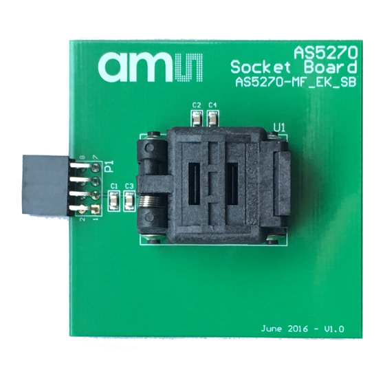
Page 4: Board Description
Pin 1 of the IC is indicated by a small white dot on the PCB. All passive components needed for proper operation are included on bottom side the PCB. Figure 2: AS5270 socket board ZIF socket for MLF-16 Connector to AS5xxx-EK- USB-PB UART Programmer ams Eval Kit Manual Page 4 [v1-01] 2017-Jul-18 Document Feedback... -
Page 5: As5270-Mf_Ek_Sb Hardware
AS5270 Socket Board AS5270-MF_EK_SB Hardware AS5270-MF_EK_SB Schematics Figure 3: AS5270-MF_EK_SB schematics AS5270 VDD3V3_B TP1_T VDD3V3_B 100nF 100nF 100nF 100nF VDD3V3_T TP1_B VDD3V3_T AS5270 OUT_B TP2_T TP4_B OUT_T TP2_B TP4_T OUT_T OUT_B Header 4X2 Size Project Title Revision AS5270-MF_EK_AB Date 17.06.2016... -
Page 6: As5270-Mf_Ek_Sb Pcb Layout
AS5270 Socket Board AS5270-MF_EK_SB PCB layout Figure 4: AS5270-MF_EK_SB PCB layout top side Figure 5: AS5270-MF_EK_SB PCB layout bottom side ams Eval Kit Manual Page 6 [v1-01] 2017-Jul-18 Document Feedback... -
Page 7: Ordering & Contact Information
For further information and requests, e-mail us at: ams_sales@ams.com For sales offices, distributors and representatives, please visit: www.ams.com/contact Headquarters ams AG Tobelbader Strasse 30 8141 Premstaetten Austria, Europe Tel: +43 (0) 3136 500 0 Website: www.ams.com ams Eval Kit Manual Page 7 [v1-01] 2017-Jul-18 Document Feedback... -
Page 8: Copyrights & Disclaimer
AG shall not be liable to recipient or any third party for any damages, including but not limited to personal injury, property damage, loss of profits, loss of use, interruption of business or indirect, special, incidental or consequential damages, of any kind, in connection with or arising out of the furnishing, performance or use of the technical data herein. -
Page 9: Revision Information
Page Initial version 1-00 Review 1-01 Note: Page numbers for the previous version may differ from page numbers in the current revision. Correction of typographical errors is not explicitly mentioned. ams Eval Kit Manual Page 9 [v1-01] 2017-Jul-18 Document Feedback... - Page 10 Mouser Electronics Authorized Distributor Click to View Pricing, Inventory, Delivery & Lifecycle Information: AS5270-MF_EK_SB...
Need help?
Do you have a question about the AS5270-MF_EK_SB and is the answer not in the manual?
Questions and answers