Table of Contents
Advertisement
Quick Links
Advertisement
Table of Contents

Related Manuals for laerdal SimMan DrugArm+LiveShock


Summary of Contents for laerdal SimMan DrugArm+LiveShock
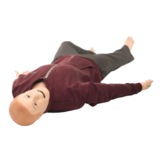
- Page 1 SimMan / DrugArm + LiveShock User Guide laerdal.com...
-
Page 2: Table Of Contents
TABLE OF CONTENTS Intended use ................. . . 4 Items included . - Page 3 Arm ..................69 Head, Neck and Airway .
-
Page 4: Intended Use
Do not mix articulated and drug recognition arms. NOTES • Read the Important Product Information booklet before use. • Read the SimMan 3G PLUS Quick Setup Guide (QSG) for more information on usage. • See Laerdal's global guarantee for terms and conditions. For more information visit www.laerdal.com. -
Page 5: Items Included
ITEMS INCLUDED... - Page 6 Neck skin (x3) 23. RFID kit 10. Lung compliance O-ring (x10) 24. Tools 11. Blood concentrate and airway lubricant 25. External power supply 12. Fill and drain bottles 13. Wounds kit 14. Chest drain pleura (x6) NOTE Visit www.laerdal.com for accessories overview.
-
Page 7: Features And Skills
FEATURES AND SKILLS The following features are available on SimMan. Features overview Assessment capabilities • Automatic Non-Invasive Blood Pressure (NIBP) • Carotid, brachial, radial, femoral, popliteal and pedal pulses... -
Page 8: Immersive Simulation
• SpO monitoring • Configurable eye, eyelid and pupil settings • Heart, lung, bowel and vocal sounds • RFID Technology for automatic recognition of drugs and airwaydevices. • Auto measurement of volume and concentration for drugs and IV fluids. Immersive simulation •... - Page 9 The following information is automatically registered in the SimMan simulation session: • Detection of proper head position • Jaw thrust • Pneumothorax decompression • Ventilations • Stomach distension Nasal Cannulation Nasal cannulation is possible with standard equipment. WARNING Do not supply oxygen. Artificial respiration Artificial respiration of SimMan can be achieved by the following methods: •...
- Page 10 • Do not put biological or other materials in the simulator’s airways. • Only use Manikin Airway Lubricant. Use of silicone or any other lubricant not approved by Laerdal may cause damage to the airways. • Refer to the Important Product Information booklet for further cautions related to the Patient Simulator airway.
-
Page 11: Clinical Interventions
Clinical interventions • Bag Valve Mask (BVM) ventilation • Laryngeal Mask (LMA) placement • Oral, nasal and endotracheal intubation • Suctioning (oral & nasopharyngeal) • Cricothyrotomy • Pneumothorax Needle Decompression and Chest tube insertion • Intramuscular (IM), Intravenous (IV) and Intraosseous (IO) injection •... - Page 12 • Cardioversion • ECG rhythm monitoring • External pacing • CPR capable NOTES • SimMan provides CPR measurement and feedback compliant with AHA 2020 guidelines. • LLEAP provides real-time feedback on the quality of depth, release and frequency of CPR. CPR compressions generate palpable pulses, blood pressure wave form, and ECG artefacts.
- Page 13 CAUTION Do not defibrillate on the ECG connectors on the Patient Simulator. This will damage the Patient Simulator. NOTES • Always follow the safety instructions from the defibrillator manufacturer when using the defibrillator on the Patient Simulator. • To prevent overheating during defibrillation, do not exceed a defibrillation sequence of 3 shocks in 45 seconds followed by 1 minute of CPR.
- Page 14 Cardioversion and external pacing Synchronised cardioversion and external pacing with or without capture SimMan enables the attachment of real electrodes for ECG rhythm monitoring at 4 sites with 3-lead ECG. 12-lead ECG display. LLEAP features an extensive ECG library and records cardiac rhythms. Refer to LLEAP Help Files for further information.
-
Page 15: Injection Sites
Injection sites Tension pneumothorax with needle decompression can be performed at the bilateral mid clavicle line, second intercostal space. Intraosseous (IO) simulation with needle insertion is possible through the left tibia. Intramuscular (IM) injections can be simulated in the upper hip. Chest tube insertion can be simulated at left or right mid-axillary line in the fourth and fifth intercostal space. -
Page 16: Drugs And Iv
Drugs and IV Drugs used by the scenario and corresponding drug concentrations can be registered manually by the instructor in the Event window in LLEAP or automatically, if you use RFID tags. For further information, see LLEAP Help. Patient Monitor Features – Drugs •... -
Page 17: Articulations
Articulations The Patient Simulator has a range of limb and joint articulation providing immersive patient handling. Joint Range of Mobility Neck 3-axis movement of the head Shoulder At least: 160° flexion of arm 30° extension of arm 70° abduction of arm 90° medial rotation Elbow Fixed, no mobility... -
Page 18: Panels Overview
Joint Range of Mobility Hip Joints 3-axis rotation Knees 1-axis rotation Ankles 1-axis rotation Panels overview Power panel 1. Power status 2. Battery status 3. Charge status No Light - Power Off Red - 0 - 20% Red - Not charging (check batteries) Green - Power On Orange - 20-70%... - Page 19 Fluid panel Air out Blood inlet Fluid inlet Activate filling...
- Page 20 An external supply of compressed air can be connected when the Patient Simulator is stationary over extended periods. Connect a suitable CO /external air source to a Laerdal external compressor or regulator panel. Connect a Laerdal double-lumen Air/CO tube from the external compressor or regulator panel to the Air/CO inlet on the panel.
-
Page 21: Recommended Sizes For Clinical Devices
16 Fr IM Needle 21 G (maximum) Mask (for ventilation) Laerdal Adult Mask 4 to 5+ Intraosseous (IO) Access Tibial: BIG Automatic Intraosseous Device, 15 G EZ-IO, 15 G x 1”, 1.8mm x 25mm Jamshidi ® Illinois Bone Marrow Aspiration/ Intraosseous Infusion Needle. -
Page 22: Software
SOFTWARE Operating software The Patient Simulator is operated and controlled by LLEAP - Laerdal Learning Application. LLEAP LLEAP is the instructor’s application from where the simulation session is run, controlled, and monitored. Installed on a laptop, PC or tablet, LLEAP can be operated in Automatic or Manual mode. -
Page 23: Network Connectivity
• Network Selector in Laerdal Simulation Home helps users connect LLEAP and Patient monitor to a wireless network and even host a network (Windows Hosted Network). For a full overview of all applications and their help files, start Laerdal Simulation Home. NOTE Refer to the Opening Laerdal Simulation Home video. - Page 24 Option 2 Router If a local or ad-hoc network is required, a router (Laerdal or user’s own) can be used. Option 3 Mobile router A portable, battery-operated router can be used for outside simulation sessions where an enterprise network may not be available.
-
Page 27: Power
POWER Turning on the simulator Press the power button. • The power status indicator turns orange. • The Patient Simulator says “Simulator started”. • The eyes blink and there is visible chest rise. Charging the Simulator • Battery charging time is approximately 3 hours. Once fully charged, the batteries can last for up to 4 hours. - Page 28 CAUTIONS • Do not run the Patient Simulator for more than 1 minute on a single battery. • After the Patient Simulator is turned off, wait 20 seconds before restarting or the Patient Simulator may not function properly. • Never store fully charged batteries for longer than a month. •...
-
Page 29: Setup Batteries
Setup batteries SimMan is powered by 2 Laerdal Lithium Ion (Li-Ion) batteries. Always use 2 batteries together to power the Simulator and ensure that they are connected properly. Ensure the Patient Simulator is switched off. Before starting, follow the procedure. - Page 30 Disconnect the battery cable from the torso cable as shown. Charge battery...
- Page 31 Insert battery and connect battery to the torso cable as shown. Replace cover once battery/batteries are connected and in place. WARNING Inserting and connecting batteries incorrectly, short circuiting or exposure to fluids pose an explosion hazard. CAUTIONS • Ensure the LiveShock cable has been disconnected. •...
-
Page 32: Charging The Batteries
Charging the batteries The Patient Simulator battery charger comes with 5 interchangeable international plugs which can be used to externally charge batteries outside of the Patient Simulator. NOTE The charger should only be used with Laerdal Li-ion batteries. -
Page 33: Prepare For Simulation
PREPARE FOR SIMULATION IV catheters The right IV arm comes with a US catheter type as default. This can be replaced with an international catheter type (commonly used in Europe) with an extra flush port. US catheter International Catheter NOTE Remove arm skin before changing the catheter. - Page 34 Unzip and fold down the IV arm skin to expose the IV catheter module. Using a #4 Phillips screwdriver; unscrew the two screws of the module and pull the IV module out of the arm. Disconnect the two fluid tubes from the IV module Discard the old module and insert it into the IV arm.
- Page 35 Setup for IV drip and drug administration To simulate an IV drip, connect the international catheter and tube setup as shown.
- Page 36 For more information on connecting the US IV drip catheter, contact your local Laerdal service centre. Administering IV fluids To prevent clogging of the IV system, use only purified water to simulate IV drugs with SimMan.
- Page 37 Before Each Session Attach the IV overflow tube to the fluid drain under the Patient Simulator’s right arm. Allow excess fluid to drain into a container during the simulation. Calibrating the IV Arm Flowmeter in LLEAP To calibrate the flow meter in the IV arm:...
- Page 38 Click on the Tools, Maintenance menu in LLEAP, then select the Calibrate IV flow meter option. Follow the on-screen instructions in the Flowmeter calibration wizard. A confirmation message will appear if the calibration was successful. RFID tag The SimMan RFID (Radio Frequency Identification) system, features two antennae locations: one in the mouth and another in the right arm.
- Page 39 Attach a strip of hook and loop tape (i.e. Velcro) to the syringe or airway device of your choice. If you are using stickers, place the RFID sticker on the pre-printed RFID tag. NOTES • When applying tags to syringes, ensure that the tag is as close as possible to the needle end.
- Page 40 RFID Tag use for Airway Devices For reliable RFID recognition in the mouth region, ensure that the RFID tagged device is brought within range of the antenna. The range of the mouth antenna is approximately 10cm. IV Setup for RFID Recognition You can use your own equipment to set IV extension tubing.
- Page 41 Calibration of BP in LLEAP...
- Page 42 Select Tools, Maintenance, and choose Calibrate BP. Follow the onscreen wizard instructions to perform the calibration. SpO2 monitoring The SimMan SpO2 probe is made up of a light diode and light sensor. When the beam between the diode and sensor is broken, the Patient Monitor Application registers that the SpO2 probe is connected.
- Page 43 Connect the probe’s USB plug to the Patient Monitor PC. The probe can be placed on any suitable area on the Patient Simulator, Ensure that the probe is always firmly fixed in position.
-
Page 44: Torso
An external supply of compressed air can be connected when the Patient Simulator is stationary over extended periods. Connect a suitable CO /external air source to a Laerdal external compressor or regulator panel. Connect a Laerdal double-lumen Air/CO tube from the external compressor or regulator panel to the Air/CO inlet on the panel. - Page 45 CO connection limits. • For more information on external compressors and regulator panels compatible with SimMan, contact your local Laerdal representative. Attaching a wound Ensure that the area where the wound is to be applied is clean and dry.
- Page 46 Remove wounds kit once cleaning is complete. Clean any tape residue left on the Patient Simulator skin with Laerdal Manikin Wipes. NOTE When removing wound tubing from the blood ports, cover the Patient Simulator skin with a cloth to prevent staining.
- Page 47 Remove the Patient Simulator’s genitalia pad by gripping the pad pulling forward and down. Select new genitalia module. Connect the new genitalia module’s urine tube and the catheterization sensor cable from inside the Patient Simulator pelvis to the urine bladder module.
-
Page 48: Head, Neck And Airway
Head, Neck and Airway Insert the head skin Position the head skin over the head module Align the eye sockets over the eyes. Align the airway tube with the right nostril, and secure into place. - Page 49 Insert the microphone carefully and connect the red, blue and green tube connectors. Turn the head to the other side and insert the microphone. Connect the red and blue tube connectors.
- Page 50 Close the zipper. Place the neck skin. Prepare teeth Soft upper teeth may be replaced with a hard set for enhanced realism while practicing intubations. Grip soft teeth with two fingers. Remove soft upper teeth.
- Page 51 Select new teeth. Align new teeth with the gums and push back until the teeth engage and lock onto the gums. Airway intubation Lubricate airway device. Insert lubricated device into the airway. CAUTION Do not spray lubricant directly into the airway.
-
Page 52: Prepare Simulated Blood & Fluids
The use of smaller tube-type devices reduces wear of the Patient Simulator’s airways. Prepare simulated blood & fluids Preparing simulated blood Fill blood fill bottle with approximately 500 ml distilled water. Add approximately 10 drops of Laerdal Blood colored concentrate. Tighten the cap and mix. - Page 53 Preparing clear fluids and secretions Fill fluid fill bottle with approximately 500 ml distilled water. Tighten the cap. Blood and fluid systems The Patient Simulator has two internal tanks, one for simulated blood and one for fluids.The fluid fill panel is located at the top of the right leg. How-to video: in LLEAP.
- Page 54 Roll the right leg skin down to expose the fill panel. Lift the panel cover. Connect the blood fill bottle tubes to the relevant inlet and the air outlet in the right leg panel. Turn on the Activate Filling. The button will light up and blood will flow into the Patient Simulator.
- Page 55 Roll the right leg skin down to expose the fill panel. Lift the panel cover. Connect the fluid fill bottle tubes to the relevant inlet and the air outlet in the right leg panel. Turn on the Activate Filling. The button will light up and fluid will flow into the Patient Simulator.
- Page 56 NOTES • Disconnect tubes from the Patient Simulator before turning off the Activate Fill button. Turning the fill button off before disconnecting the tubes will initiate draining of the tank. • Only one tank can be filled at a time. Secretions, sweat and urine Sweat, tears, cerebrospinal fluid (CSF) and urine functions can be set and adjusted in the LLEAP Fluids tab.
-
Page 57: Leg
Prepare tibial IO with blood... - Page 58 Attach an IV bag to the tibial tube. Close off the pinch clamp. Roll down leg skin to access the tibial IO module. Remove the IO tape. Lift out the module from the leg. Remove the tube from the module. Fill the module with 30-35 ml of simulated blood.
- Page 59 Recommended device sizes EZ-IO, 15 G x 1” 1.8 x 25 mm Jamshidi ® Illinois Bone Marrow Aspiration/Intraosseous 18 G Infusion Needle 9/16” (14 mm) - 1 ½” (38 mm) CAUTION Do not inject fluids into these pads unless approved IO modules with fluid outlets are in place.
-
Page 60: Maintenance
MAINTENANCE Torso Open the torso skin Some maintenance tasks can only be carried out by opening the torso skin. Unzip the skin at shoulders and torso. Remove the genitalia pad. Release the skin flap. Move the torso skin to the side. - Page 61 NOTE Ensure that the tubes and cables are connected to the stomach foam. Replace the pneumothorax bladders Replace the pneumothorax bladders after multiple decompressions. Before starting, follow the procedure. Open the torso skin (p. 60) Lift the chest plate to expose pneumothorax bladders. Slide the bladder(s) out.
- Page 62 Discard used bladder(s). Select new bladder.
- Page 63 Slide bladder into place. Reconnect tube to the bladder. Replace chest plate.
- Page 64 Replace the chest rise bladders Replace the chest rise bladders if they leak or are damaged. Before starting, follow the procedure. Open the torso skin (p. 60) Lift the chest plate to expose the chest rise bladders (one on each side). Disconnect the tube(s).
- Page 65 Replace the chest drain pleura Before starting, follow the procedure. Open the torso skin (p. 60) Remove the used chest drain pleura module. Remove and discard the pleura skin from the module. Replace the used pleura skin with a new one. Insert the module into the torso.
- Page 66 Replace the lung bladders Replace the lung bladders if they leak or are damaged. Before starting, follow the procedure. Open the torso skin (p. 60) Lift the chest and chest rise plates. Unhook the green lung compliance bands on each side of the lung assembly.
- Page 67 Lift the hinged lung plate. Remove the used lung from the socket. Discard the used lung. Select the new lung bladder. Insert the new lung bladder into the socket. Ensure that the string is placed in the lung bladder fold. Close the hinged lung plate.
- Page 68 Ensure the Patient Simulator is turned off. Open the torso skin (p. 60) Disconnect the filter from the leg and pelvis blood tubes by unscrewing the black connectors at each end. Remove filter from the Patient Simulator. Discard clogged filter. Select a new filter.
-
Page 69: Arm
Remove the back torso skin section. Close the torso skin Put the torso skin over the torso. Push down the skin flap over the genitalia area. Attach the genitalia pad. Zip the torso at the shoulders and torso. Replacing IV Arm Catheter/Filter Replace the IV catheter module if it is damaged or if resistance is unrealistically high when injecting fluids. - Page 70 Unzip and fold down the IV arm skin to expose the IV catheter module. Using the no. 4 Phillips screwdriver; remove the 4 screws and pull the IV module out of the arm. Lift the IV catheter up and out, exposing the recess where the filter is located.
- Page 71 Remove the arm Before starting, follow the procedure. Open the torso skin (p. 60) Lift the chest plate to expose the arm bolt.
- Page 72 a. Unscrew the arm bolt. Do not unscrew fully b. Lift up the arm bolt. Remove the arm. Replace the arm • Take the new arm. How-to video: How to Replace Arms...
- Page 73 Attaching the left arm Insert the arm in its socket a. Screw the arm bolt. b. Push down on the arm bolt.
-
Page 74: Head, Neck And Airway
Close the chest plate Head, Neck and Airway Replacing cricothyroid tape and neck skin After creating an emergency airway through the cricothyroid membrane, replace the perforated tape before starting a new simulation session. - Page 75 Remove the neck skin. Remove damaged or perforated tape. Select a new section of cricothyroid tape. Replace with new tape, ensuring it completely covers and seals the opening to prevent leakage during ventilation. Replace the neck skin. NOTE If the used neck skin is in good condition, move the skin along to position a new section over the cricothyroid tapeIf the used neck skin is in good condition, move the skin along to position a new section over the cricothyroid tape.
- Page 76 Remove Head Skin...
- Page 77 Remove the neck skin. Unzip the head skin. Lift the head skin to expose tubing. Disconnect the blue and red tube connectors. Carefully remove the microphone cable from inside the head skin. Turn the head. Disconnect the red, blue and green tube connectors. Carefully remove the microphone cable from inside the head skin.
- Page 78 Replace the head skin Select the new head skin. Unzip the head skin. Turn the head skin inside out.
- Page 79 Insert the head skin Position the head skin over the head module Align the eye sockets over the eyes. Align the airway tube with the right nostril, and secure into place.
- Page 80 Insert the microphone carefully and connect the red, blue and green tube connectors. Turn the head to the other side and insert the microphone. Connect the red and blue tube connectors.
- Page 81 Close the zipper. Place the neck skin.
-
Page 82: Leg
Removing the left leg Before starting, follow the procedure. Open the torso skin (p. 60) Move stomach foam to one side. Disconnect the cables to the left leg. Pull out the thumb lock pin. Carefully remove the leg. - Page 83 Replacing tibial IO...
- Page 84 Attach the tibial IO drain bag to the tibial tube. Close off the pinch clamp. Roll down leg skin to access the tibial IO module. Remove the IO tape. Lift out the tibial IO unit from the leg. Remove the tube from the tibial IO module. Remove the tibial IO pad from the tibial IO chassis.
- Page 85 11. Connect the tibial tube to the tibial IO unit. 12. Insert the tibial IO module into the leg. 13. Secure the module with tape. 14. Roll the leg skin over the tibial module.
-
Page 86: General Care And Cleaning
GENERAL CARE AND CLEANING Regular care, cleaning and maintenance are required to ensure longevity of the Patient Simulator. General patient simulator care • Wash hands before use and place the Patient Simulator on a clean surface to maintain Patient Simulator skins. •... -
Page 87: Cleaning The Iv Arm
• Wipe the skin with a moist cloth to remove stains. Remove wet clothes or linens. Glue residue from the wound module tapes may be removed with a moist cloth. Cleaning the IV Arm Daily cleaning When the day’s sessions are done, flush the IV Arm with air to remove any fluid/liquid in the system. -
Page 88: Clothing
Laerdal representative for more information. Cleaning the blood system Once all sessions are complete, flush the Blood System with distilled water, with the wounds connected.This will remove remains of Laerdal blood in the Blood System, and prevent clogging of valves and tubing. - Page 89 Emptying internal blood tank Connect an empty fill bottle to the bood inlet. Fluid from the internal tank will automatically drain into the fill bottle. When the flow stops, disconnect the blood connector. WARNING Connecting a full Blood Unit to a Patient Simulator with an already full internal tank will result in system overflow.
- Page 90 NOTE Place the fill bottle on the floor or below the Patient Simulator to facilitate emptying the fluids. How-to video: Empty Internal Blood Reservoir NOTE The video shows the fluid inlets. Use the blood inlet here. Empty the blood system Ensure a wound is connected to a blood outlet.
-
Page 91: Cleaning The Fluid System
In LLEAP uncheck all boxes and slide bleeding rate controls to the left. And then disconnect bottle. Flush the isopropanol out of the blood system Connect an empty fill bottle to the fill panel. Connect an empty fill bottle to the blood and air connector; the filling of air into the internal tank will start. - Page 92 NOTE The video shows the fluid inlets. Use the fluid inlet here.
-
Page 93: Accessories
ACCESSORIES Trauma modules Trauma modules can be fitted to the Patient Simulator to simulate bleeding patient cases. After the simulation is complete, leave the trauma modules connected, and clean according to the instructions in Cleaning the Blood System (p. 88) - Page 94 NOTES • The SimMan arm adaptor kit is required to connect the trauma arm modules. • There will be no automatic non-invasive blood pressure functionality on the right arm when it is used with one of the left trauma arms. How-to video: in LLEAP.
- Page 96 Select either the SimMan Amputation or Gunshot Arm with Arm Adapter and Adapter Screw. Unscrew the Adapter Screw. Insert the arm into the shoulder bracket. a. Tighten the arm bolt to secure. b. Push down the arm bolt. Attach the tube to the desired blood port.
- Page 97 Tighten the screw to adjust the range of the arm motion with a screwdriver. CAUTION Do not over rotate arm. Over rotating the arm may cause the red vinyl tubing to disconnect. Attaching the trauma left leg Insert the trauma leg into the leg socket.
-
Page 98: Transport And Storage
Insert the thumb lock pin, ensuring the leg is properly fixed into place. Connect the cables and tube. Transport and storage The Simulation System is supplied with two cases for easy transport and storage; one for the Patient Simulator legs and one for the torso. Before storage or shipping •... - Page 99 CAUTIONS • Do not store this product outside the storage conditions specified in the Important Product Information. • Store simulator in a clean, dry area. Storage in a damp area will cause corrosion of electronic parts. • Remove stomas prior to storage. Stomas should be stored in a plastic bag when not in use.
- Page 100 © 2023 Laerdal Medical AS. All rights reserved. Laerdal Medical AS P.O. Box 377 Tanke Svilandsgate 30, 4002 Stavanger, Norway T: (+47) 51 51 17 00 20-21551 Rev A laerdal.com...
Need help?
Do you have a question about the SimMan DrugArm+LiveShock and is the answer not in the manual?
Questions and answers